


 Loading...
TI01099T/09/EN/05.18
71419903
2018-12-07
Products |
Solutions |
Services |
|
|
|
Technical Information iTHERM TT411
Welded thermowell
Use in hygienic and aseptic applications in the food & beverages and pharmaceutical industries
Applications
•Specially designed for use in hygienic and aseptic applications in the Food & Beverages and Life Sciences industries
•Pressure range up to 40 bar (580 psi)
•For increased protection requirements of the temperature sensor regarding physical and chemical effects
•For use in pipes and containers or tanks
•Ideally suited to all measuring points that require regular recalibration by simply replacing the insert in closed processes
Your benefits
•iTHERM QuickNeck – cost and time savings thanks to simple, tool-free recalibration of the insert used
•Over 50 hygienic process connections
•Global portfolio with metric and imperial versions
•International certification: 3-A Sanitary Standard, EHEDG, ASME BPE, FDA, TSE Certificate of Suitability
•Optional: 1.4435 material, delta ferrite content < 0.5%
•Fast response time owing to reduced tips with thin walls
•State of the art T-pieces and elbow pieces, no welds and dead legs with best-in- class hygienic design

|
iTHERM TT411 |
|
|
|
Installation |
|
|
Orientation |
No restrictions. However, self-draining in the process must be guaranteed. If there is an opening to |
|
detect leaks at the process connection, this opening must be at the lowest possible point. |
|
|
Installation instructions |
The immersion length of the thermometer can influence the accuracy. If the immersion length is too |
|
small then errors in the measurement are caused by heat conduction via the process connection and |
|
the container wall. If installing into a pipe then the immersion length should ideally be half of the |
|
pipe diameter. |
|
Installation possibilities: Pipes, tanks or other plant components |
U |
3 |
4 |
1 |
|
|
≥ 3° |
|
|
|
2 |
|
≥ 3° |
|
|
|
|
A0008946 |
1 Installation examples
1, 2 Perpendicular to flow direction, installed at a min. angle of 3° to ensure self-draining
3On elbows
4 Inclined installation in pipes with a small nominal diameter
UImmersion length
In the case of pipes with a small nominal diameter, it is advisable for the tip of the thermometer to project well into the process so that it extends past the pipe axis. Installation at an angle (4) could be another solution. When determining the immersion length or installation depth all the parameters of the thermometer and of the medium to be measured must be taken into account (e.g. flow velocity, process pressure).
For immersion lengths U < 70 mm (27.5 in), the use of iTHERM QuickSens inserts is recommended..
1 |
2 |
Sensor with |
|
|
|
milk pipe |
Sensor with Varivent |
||
connection |
connection |
|
|
Groove |
|
|
|
slip-on nut |
|
|
|
|
Companion |
O-ring |
|
Companion |
connection |
||
|
|||
connection |
|
|
|
Sealing
Centering ring
R0.4 |
R0.4 |
3 |
|
4 |
|
|
|
|||
|
|
|
|
|
|
|
|
|
|
|
|
|
|
|
|
|
|
|
|
|
|
|
|
|
|
|
|
|
|
|
|
|
|
|
|
Shaped gasket
Companion |
connection |
Pressure ring |
O-ring
Welding boss
Vessel wall
A0011758-EN
2 Detailed installation instructions for hygiene-compliant installation
1Sanitary connection according to DIN 11851, only in conjunction with self-centering sealing ring as per EHEDG position paper
2Varivent® process connection for VARINLINE® housing
3 Clamp as per ISO 2852, only in conjunction with seal as per EHEDG position paper
4Process connection Liquiphant-M G1", horizontal installation
2 |
Endress+Hauser |

iTHERM TT411
The counterpieces for the process connections and the seals or sealing rings are not included in the scope of supply for the thermometer. Liquiphant M weld-in adapters with associated seal kits are available as accessories. .
The following action must be taken if a sealing ring (O-ring) or seal fails:
•Remove the thermometer, clean the thread and the O-ring joint/sealing surface
•Replace the sealing ring or seal
•Perform CIP after installation
In the case of weld-in connections, exercise the necessary degree of care when performing the welding work on the process side:
•Suitable welding material
•Flush-welded or with welding radius >= 3.2 mm (0.13 in)
•No recesses, folds or gaps
•Honed and polished surface, Ra ≤ 0.76 µm (30 µin)
|
Process |
|
|
Process temperature range |
Maximum –200 to +650 °C (–328 to +1 202 °F)→ 13 |
|
|
Thermal shock |
Thermal shock resistance in CIP/SIP process with a temperature increase and decrease from |
|
+5 to +130 °C (+41 to +266 °F) within 2 seconds. |
|
|
Process pressure range |
The maximum possible process pressure depends on various influencing factors, such as the design, |
|
process connection and process temperature. For information on the maximum possible process |
|
pressures for the individual process connections, see the 'Process connection' section. → 13 |
|
It is possible to check the mechanical loading capacity as a function of the installation and |
|
process conditions online in the TW Sizing Module for protection tubes in the Endress+Hauser |
|
Applicator software. This is valid for DIN thermowell calculations. See 'Accessories' section. |
|
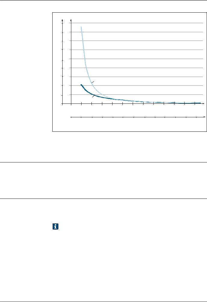
Example of the permitted flow velocity depending on the immersion length and process |
|
medium |
|
The highest flow velocity tolerated by the protection tube diminishes with increasing insert |
|
immersion length exposed to the stream of the fluid. In addition, it is dependent on the diameter of |
|
the tip of the protection tube, the medium type, process temperature and process pressure. The |
|
following figures exemplify the maximum permitted flow velocities in water and superheated steam |
|
at a process pressure of 40 bar (580 PSI). |
Endress+Hauser |
3 |
iTHERM TT411
V (FT/S) V (M/S) |
|
|
|
|
|
|
|
|
|
|
|
||
290 |
90 |
|
|
|
|
|
|
|
|
|
|
|
|
260 |
80 |
|
|
|
|
|
|
|
|
|
|
|
|
230 |
70 |
|
|
|
|
|
|
|
|
|
|
|
|
200 |
60 |
|
|
|
|
|
|
|
|
|
|
|
|
|
|
|
|
|
|
|
|
|
|
|
|
|
|
160 |
50 |
|
|
|
|
|
|
|
|
|
|
|
|
|
|
|
|
|
|
|
|
|
|
|
|
|
|
130 |
40 |
|
|
|
|
|
|
|
|
|
|
|
|
100 |
30 |
|
|
|
|
|
|
|
|
|
|
|
|
|
|
|
B |
|
|
|
|
|
|
|
|
|
|
65 |
20 |
|
|
|
|
|
|
|
|
|
|
|
|
30 |
10 |
|
|
|
|
|
|
|
|
|
|
|
|
|
|
A |
|
|
|
|
|
|
|
|
|
|
|
|
|
|
|
|
|
|
|
|
|
|
|
|
|
0 |
|
|
|
|
|
|
|
|
|
|
|
|
|
|
|
0 |
100 |
|
200 |
|
300 |
|
400 |
|
500 |
|
600 |
|
|
|
|
|
|
|
|
L (MM) |
|
|
|
|
|
|
0 |
2 |
4 |
6 |
8 |
10 |
12 |
14 |
16 |
18 |
20 |
22 |
24 |
|
|
||||||||||||
|
|
|
|
|
|
|
|
L (IN) |
|
|
|
|
|
|
|
|
|
|
|
|
|
|
|
|
|
|
A0032462 |
3 Permitted flow velocities, protection tube diameter 9 mm (0.35 in)
AMedium water at T = 50 °C (122 °F)
B Medium superheated steam at T = 160 °C (320 °F)
L Immersion length exposed to flow
vFlow velocity
Medium - state of |
Gaseous or liquid (also with high viscosity, e.g. yogurt). |
aggregation |
|
Mechanical construction
Design, dimensions |
All dimensions in mm (in). The design depends on the thermowell version: |
•Diameter 6 mm (¹⁄ in)
•Diameter 9 mm (0.35 in)
•Diameter 12.7 mm (¹⁄ in)
•T-piece and elbow piece thermowell version as per DIN 11865 / ASME BPE for weld-in
Various dimensions, such as the immersion length U for example, are variable values and are therefore indicated as items in the following dimensional drawings.
Variable dimensions:
Position |
Description |
|
|
L |
Thermowell length (U+T) |
|
|
B |
Thermowell base thickness: predefined, depends on thermowell version (see also the individual |
|
table data) |
|
|
T |
Length of thermowell lagging: variable or predefined, depends on thermowell version (see also the |
|
individual table data) |
|
|
U |
Immersion length: variable, depending on the configuration |
|
|
4 |
Endress+Hauser |
iTHERM TT411
Thermowell diameter 6 mm (¹⁄ in)
|
|
|
|
|
|
|
|
|
|
!30 |
|
|
|
|
|
|
|
|
|
|
|
(1.81) |
|
|
G3/8" |
|
|
|
|
|
|
|
|
(1.34) |
(1.77) |
|
|
|
|
|
|
|
|
|
34 |
45 |
|
|
|
|
|
|
|
|
|
|
|
||
T |
|
|
|
|
|
|
|
|
|
T |
|
|
|
|
|
|
|
|
|
|
|
|
|
|
|
|
|
|
|
|
|
|
|
G3/8" |
|
L |
|
|
|
|
|
|
|
|
L |
!6 (¼) |
|
|
|
|
|
|
|
|
|
|
|||
U |
!6 (¼) |
|
|
|
|
|
|
|
|
U |
|
|
|
|
|
|
|
|
|
|
|
||
|
|
|
|
|
|
|
|
|
|
|
|
1 |
2 |
3 |
4 |
5 |
6 |
7 |
8 |
9 |
|
10 |
|
|
|
|
|
|
|
|
|
|
|
|
A0019699 |
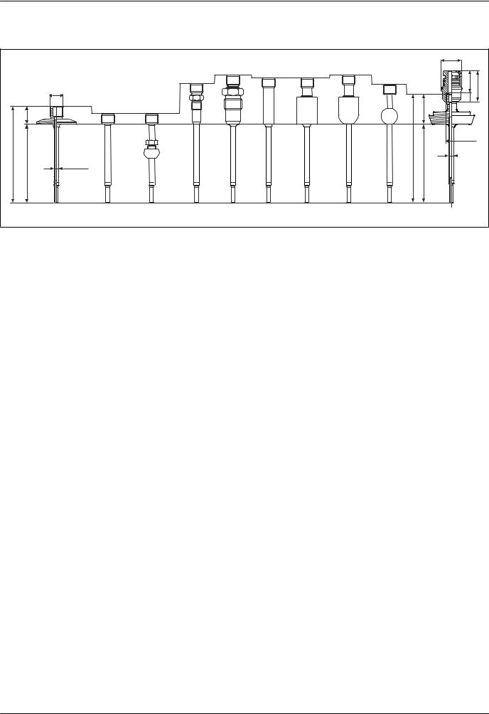
4 Thermowell with extension neck connection G3/8" and various process connection versions:
1Clamp version
2Without process connection
3 Spherical compression fitting TK40
4 Metal sealing system M12x1
5Metal sealing system G½"
6 Cylindrical weld-in adapter 12 x 40 mm
7Cylindrical weld-in adapter 30 x 40 mm
8 Spherical-cylindrical weld-in adapter 30 x 40 mm
9Spherical weld-in adapter 25 mm
10Sanitary connection according to DIN 11851 with threaded bottom part iTHERM QuickNeck, torque 5 Nm (3.69 lbf ft), glued with loctite® 270.
Position |
Version |
Length |
|
|
|
|
|
|
Metal sealing system M12x1 |
46 mm (1.81 in) |
|
|
|
|
|
|
Metal sealing system G½" |
60 mm (2.36 in) |
|
|
|
|
|
|
Tri-clamp (0.5"-0.75") |
24 mm (0.94 in) |
|
|
|
|
|
|
Microclamp (DN8-18) |
23 mm (0.91 in) |
|
|
|
|
|
|
Clamp DN12 according to ISO 2852 |
24 mm (0.94 in) |
|
|
|
|
|
Length of thermowell |
Clamp DN25/DN40 according to ISO 2852 |
21 mm (0.83 in) |
|
|
|
||
Sanitary connection DN25/DN32/DN40 according to DIN |
29 mm (1.14 in) |
||
lagging T 1) |
|||
|
11851 |
|
|
|
|
|
|
|
Spherical-cylindrical weld-in adapter |
58 mm (2.28 in) |
|
|
|
|
|
|
Cylindrical weld-in adapter 12 mm (0.47 in) |
55 mm (2.17 in) |
|
|
|
|
|
|
Without process connection (only G3/8" thread) |
11 mm (0.43 in) |
|
|
|
|
|
|
Cylindrical weld-in adapter |
55 mm (2.17 in) |
|
|
|
|
|
|
Spherical weld-in adapter |
47 mm (1.85 in) |
|
|
|
|
|
|
|
Variable, depending |
|
Immersion length U |
Independent of the version |
on the |
|
|
|
configuration |
|
|
|
|
|
Base thickness B |
Reduced tip 4.3 mm (0.17 in) |
2 mm (0.08 in) |
|
|
|
|
1)Depends on the process connection
Endress+Hauser |
5 |

iTHERM TT411
Thermowell diameter 9 mm (0.35 in)
|
M24x1.5 |
|
|
|
|
|
|
|
T |
!15 (0.6) |
|
|
|
|
|
|
|
|
|
|
|
|
|
|
|
|
|
!9 |
|
|
|
|
|
|
|
U |
(0.35) |
|
|
|
|
|
|
|
|
|
|
|
|
|
|
|
|
B |
|
|
|
|
|
|
|
|
1 |
2 |
3 |
4 |
5 |
6 |
7 |
|
8 |
|
|
|
|
|
|
|
T |
|
|
|
|
|
|
|
|
|
!25 |
|
|
|
|
|
|
|
|
(0.98) |
|
|
|
|
|
|
|
|
!9 |
|
|
|
|
|
|
|
U |
(0.35) |
|
|
|
|
|
|
|
|
|
|
|
|
|
|
|
|
|
B |
9 |
10 |
|
11 |
12 |
13 |
|
|
14 |
|
|
|
|
|
|
|
|
A0019729 |
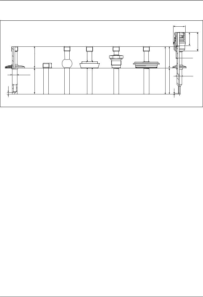
5 Thermowell with M24x1.5 connection thread and the following process connection versions:
1Clamp as per ISO2852
2Cylindrical weld-in adapter 30 x 40 mm
3 Spherical-cylindrical weld-in adapter 30 x 40 mm
4Spherical weld-in adapter 25 mm
5Sanitary connection according to DIN 11851
6 Aseptic pipe union according to DIN 11864-1 Form A
7Metal sealing system G½"
8 Thread according to ISO 228 for Liquiphant weld-in adapter 9 APV Inline
10Varivent®
11Ingold connection
12SMS 1147
13Neumo Biocontrol
14Ingold connection, for example with bottom part iTHERM QuickNeck
Position |
Version |
Length |
|
|
|
|
|
Length of thermowell lagging T, without quick-fastening iTHERM |
Variable, depending on the |
||
QuickNeck |
|
configuration |
|
|
|
|
|
|
SMS 1147, DN25 |
40 mm (1.57 in) |
|
|
|
|
|
|
SMS 1147, DN38 |
41 mm (1.61 in) |
|
With quick-fastening |
|
|
|
SMS 1147, DN51 |
42 mm (1.65 in) |
||
iTHERM QuickNeck, |
|||
|
|
||
depending on the |
Varivent®, type F, D = 50 mm (1.97 in) |
52 mm (2.05 in) |
|
process connection |
|
||
Varivent®, type N, D = 68 mm (2.67 in) |
|||
|
|
||
|
Varivent®, type B, D = 31 mm (1.22 in) |
56 mm (2.2 in) |
|
6 |
Endress+Hauser |

iTHERM TT411
Position |
Version |
Length |
|
|
|
|
|
|
G1" thread according to ISO 228 for Liquiphant |
77 mm (3.03 in) |
|
|
weld-in adapter |
|
|
|
|
|
|
|
Spherical-cylindrical weld-in adapter |
70 mm (2.76 in) |
|
|
|
|
|
|
Cylindrical weld-in adapter |
67 mm (2.64 in) |
|
|
|
|
|
|
Aseptic pipe union according to DIN11864-A, |
42 mm (1.65 in) |
|
|
DN25 |
||
|
|
||
|
|
|
|
|
Aseptic pipe union according to DIN11864-A, |
43 mm (1.7 in) |
|
|
DN40 |
||
|
|
||
|
|
|
|
|
Sanitary connection according to DIN 11851, |
|
|
|
DN32 |
47 mm (1.85 in) |
|
|
|
||
|
Sanitary connection according to DIN 11851, |
||
|
|
||
|
DN40 |
|
|
|
|
|
|
|
Sanitary connection according to DIN 11851, |
|
|
|
DN50 |
48 mm (1.89 in) |
|
|
|
||
|
Clamp according to ISO 2852, DN12 |
|
|
|
|
|
|
|
Clamp according to ISO 2852, DN25 |
37 mm (1.46 in) |
|
|
|
|
|
|
Clamp according to ISO 2852, DN40 |
|
|
|
|
|
|
|
Clamp according to ISO 2852, DN63.5 |
39 mm (1.54 in) |
|
|
|
|
|
|
Clamp according to ISO 2852, DN70 |
|
|
|
|
|
|
|
Microclamp (DN8-18) |
47 mm (1.85 in) |
|
|
|
|
|
|
Tri-clamp (0.5"-0.75") |
46 mm (1.81 in) |
|
|
|
|
|
|
Ingold connection 25 mm (0.98 in) x |
78 mm (3.07 in) |
|
|
30 mm (1.18 in) |
|
|
|
|
|
|
|
Ingold connection 25 mm (0.98 in) x |
94 mm (3.7 in) |
|
|
46 mm (1.81 in) |
|
|
|
|
|
|
|
Metal sealing system G½" |
74 mm (2.91 in) |
|
|
|
|
|
|
APV-Inline, DN50 |
51 mm (2.01 in) |
|
|
|
|
|
Immersion length U |
Independent of the version |
Variable, depending on the |
|
configuration |
|||
|
|
||
|
|
|
|
|
Reduced tip 5.3 mm (0.21 in)x 20 mm (0.79 in) |
|
|
|
|
|
|
Base thickness B |
Tapered tip 6.6 mm (0.26 in) x 60 mm (2.36 in) |
2 mm (0.08 in) |
|
|
|
|
|
|
Straight tip |
|
|
|
|
|
Endress+Hauser |
7 |
iTHERM TT411
Thermowell diameter 12.7 mm (¹⁄ in)
|
|
|
|
|
|
|
!30 |
|
|
|
|
|
|
|
|
|
(1.81) |
|
|
|
|
|
|
|
|
|
34 |
(1.34) |
(1.77) |
|
|
|
|
|
|
|
|
|
45 |
|
T |
|
|
|
|
T |
G3/8" |
|
|
|
|
|
|
|
|
|
|
||
|
|
T |
|
|
|
|
|
|
|
|
!12.7 |
|
|
|
|
L |
!12.7 |
|
|
|
|
|
|
|
|
|
|||
|
(0.5) |
|
|
|
|
|
|
||
|
|
|
|
|
U |
(0.5) |
|
||
|
U |
|
|
|
|
|
|||
|
|
|
|
|
|
|
|
||
B |
|
|
|
|
|
|
B |
|
|
|
|
|
|
|
|
|
|
|
|
1 |
2 |
3 |
4 |
5 |
6 |
|
7 |
|
|
|
|
|
|
|
|
|
|
|
A0019701 |
6 Thermowell with extension neck connection G3/8" and various process connection versions:
1Clamp version
2 Cylindrical weld-in adapter 12.7 mm (0.5 in)
3Spherical weld-in adapter 25 mm
4Sanitary connection according to DIN 11851
5Thread according to ISO 228 for Liquiphant weld-in adapter
6Varivent®
7Microclamp, threaded with QuickNeck bottom part, torque 5 Nm (3.69 lbf ft), and glued with loctite® 270, with reduced tip
•Thermowell made from solid bar stock drilled for L ≤ 200 mm (7.87 in)
•Thermowell welded at the tip for L > 200 mm (7.87 in)
Position |
Version |
Length |
|
|
|
|
|
Length of thermowell |
Weld-in adapter, cylindrical, |
12 mm (0.47 in) |
|
12.7 mm (¹⁄ in) |
|
||
lagging T |
|
|
|
All other process connections |
65 mm (2.56 in) |
||
|
|||
|
|
|
|
Immersion length U |
Independent of the process connection |
Variable, depending on the |
|
configuration |
|||
|
|
||
|
|
|
|
|
Reduced tip 5.3 mm (0.21 in)x |
2 mm (0.079 in) |
|
|
20 mm (0.79 in) |
|
|
|
|
|
|
Base thickness B |
Reduced tip 8 mm (0.31 in)x |
4 mm (0.16 in) |
|
|
32 mm (1.26 in) |
|
|
|
|
|
|
|
Straight tip |
6 mm (0.24 in) |
|
|
|
|
8 |
Endress+Hauser |
iTHERM TT411
T-piece thermowell version
Welded, with dead legs
|
|
|
|
!30 |
|
|
|
|
(1.81) |
|
1 |
|
|
2 |
|
|
|
|
(1.77) |
|
|
|
G3/8" |
45 |
|
|
(0.6) |
|
max. !19 |
|
|
|
(0.75) |
|
|
|
15 |
|
|
(3.31) |
X |
|
|
|
84 |
|
|
|
!3.1 (0.12) |
|
2 (0.08) |
|
|
|
|
|
|
s |
|
|
|
|
|
|
|
|
|
|
!D |
|
!4.5 (0.18) |
|
|
|
|
|
|
L |
|
|
|
|
|
A0019702 |
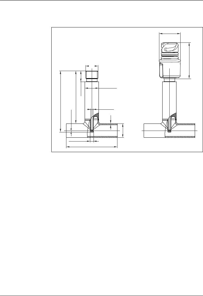
7 Thermowell as per DIN11865 or ASME BPE
1With extension neck connection G3/8"
2With threaded bottom part QuickNeck, torque 5 Nm (3.69 lbf ft), and glued with loctite® 270.
Dimensions in mm (in):
DIN11865-A |
|
|
|
DIN11865-B |
|
|
|
DIN11865-C / ASME BPE |
|
|
||||
|
|
|
|
|
|
|
|
|
|
|
|
|
|
|
|
X |
L |
D |
s |
|
X |
L |
D |
s |
|
X |
L |
D |
s |
|
|
|
|
|
|
|
|
|
|
|
|
|
|
|
DN10 |
76 (3) |
70 |
13 |
|
DN13.5 |
76 (3) |
64 |
13.5 |
|
DN12.7 |
75.6 |
95.2 |
12.7 |
|
|
|
(2.76) |
(0.51) |
|
|
|
(2.52) |
(0.53) |
|
(½") |
(2.98) |
(3.75) |
(0.5) |
|
|
|
|
|
|
|
|
|
|
|
|
|
|
|
|
DN15 |
73 |
70 |
19 |
1.5 |
DN17.2 |
73 |
68 |
17.2 |
1.6 |
DN19.0 |
72.5 |
101.6 |
19.05 |
1.65 |
|
(2.87) |
(2.76) |
(0.75) |
(0.06) |
|
(2.87) |
(2.68) |
(0.68) |
(0.063) |
5 (¾") |
(2.85) |
(4) |
(0.75) |
(0.065) |
|
|
|
|
|
|
|
|
|
|
|
|
|
|
|
DN25 |
68 |
100 |
29 |
|
DN21.3 |
71 |
72 |
21.3 |
|
DN38.1 |
63 |
120.6 |
38.1 |
|
|
(2.68) |
(3.94) |
(1.14) |
|
|
(2.8) |
(2.8) |
(0.84) |
|
(1½") |
(2.48) |
(4.75) |
(1.5) |
|
|
|
|
|
|
|
|
|
|
|
|
|
|
|
|
Endress+Hauser |
9 |
Loading...