


 Loading...
BA01275C/07/EN/06.20
71473306
2020-03-16
Products |
Solutions |
Services |
|
|
|
Operating Instructions
Turbimax CUS52D
Turbidity sensor


Turbimax CUS52D |
Table of contents |
|
|
Table of contents |
|
|
1 |
About this document . . . . . . . . . . . . . . . . |
4 |
1.1 |
Warnings . . . . . . . . . . . . . . . . . . . . . . . . . . . . |
4 |
1.2 |
Symbols used . . . . . . . . . . . . . . . . . . . . . . . . . . |
4 |
1.3 |
Symbols on the device . . . . . . . . . . . . . . . . . . . |
4 |
2 |
Basic safety instructions . . . . . . . . . . . . |
5 |
2.1 |
Requirements for personnel . . . . . . . . . . . . . . . |
5 |
2.2 |
Designated use . . . . . . . . . . . . . . . . . . . . . . . . |
5 |
2.3 |
Workplace safety . . . . . . . . . . . . . . . . . . . . . . . |
5 |
2.4 |
Operational safety . . . . . . . . . . . . . . . . . . . . . . |
6 |
2.5 |
Product safety . . . . . . . . . . . . . . . . . . . . . . . . . |
6 |
3 |
Product description . . . . . . . . . . . . . . . . . |
7 |
3.1 |
Product design . . . . . . . . . . . . . . . . . . . . . . . . . |
7 |
4Incoming acceptance and product
|
identification . . . . . . . . . . . . . . . . . . . . . . |
. 8 |
4.1 |
Incoming acceptance . . . . . . . . . . . . . . . . . . . . |
8 |
4.2 |
Product identification . . . . . . . . . . . . . . . . . . . |
. 8 |
4.3 |
Scope of delivery . . . . . . . . . . . . . . . . . . . . . . . |
9 |
4.4 |
Certificates and approvals . . . . . . . . . . . . . . . . |
9 |
5 |
Installation . . . . . . . . . . . . . . . . . . . . . . . |
10 |
5.1 |
Installation conditions . . . . . . . . . . . . . . . . . . |
10 |
5.2 |
Mounting the sensor . . . . . . . . . . . . . . . . . . . |
15 |
5.3 |
Post-installation check . . . . . . . . . . . . . . . . . . |
20 |
6 |
Electrical connection . . . . . . . . . . . . . . |
21 |
6.1 |
Connecting the sensor . . . . . . . . . . . . . . . . . . |
21 |
6.2 |
Ensuring the degree of protection . . . . . . . . . . |
22 |
6.3 |
Post-connection check . . . . . . . . . . . . . . . . . . |
22 |
7 |
Commissioning . . . . . . . . . . . . . . . . . . . . |
23 |
7.1 |
Function check . . . . . . . . . . . . . . . . . . . . . . . |
23 |
8 |
Operation . . . . . . . . . . . . . . . . . . . . . . . . . |
24 |
8.1Adapting the measuring device to the process
conditions . . . . . . . . . . . . . . . . . . . . . . . . . . . 24
9 |
Diagnostics and troubleshooting . . . |
35 |
9.1 |
General troubleshooting . . . . . . . . . . . . . . . . . |
35 |
10 |
Maintenance . . . . . . . . . . . . . . . . . . . . . . |
36 |
10.1 |
Maintenance tasks . . . . . . . . . . . . . . . . . . . . . |
36 |
11 |
Repair . . . . . . . . . . . . . . . . . . . . . . . . . . . . |
37 |
11.1 |
General information . . . . . . . . . . . . . . . . . . . |
37 |
11.2 |
Spare parts . . . . . . . . . . . . . . . . . . . . . . . . . . |
37 |
Endress+Hauser
11.3 Return . . . . . . . . . . . . . . . . . . . . . . . . . . . . . . 37
11.4 Disposal . . . . . . . . . . . . . . . . . . . . . . . . . . . . 37
12 Accessories . . . . . . . . . . . . . . . . . . . . . . . 38
12.1 Assemblies . . . . . . . . . . . . . . . . . . . . . . . . . . 38 12.2 Holder . . . . . . . . . . . . . . . . . . . . . . . . . . . . . . 39 12.3 Mounting material . . . . . . . . . . . . . . . . . . . . . 39 12.4 Compressed air cleaning . . . . . . . . . . . . . . . . 39 12.5 Ultrasonic cleaning . . . . . . . . . . . . . . . . . . . . 40 12.6 Bubble trap . . . . . . . . . . . . . . . . . . . . . . . . . . 40 12.7 Solid state reference . . . . . . . . . . . . . . . . . . . 41 12.8 Calibration vessel . . . . . . . . . . . . . . . . . . . . . . 41
13 Technical data . . . . . . . . . . . . . . . . . . . . 42
13.1 Input . . . . . . . . . . . . . . . . . . . . . . . . . . . . . . . 42 13.2 Performance characteristics . . . . . . . . . . . . . . 42 13.3 Environment . . . . . . . . . . . . . . . . . . . . . . . . . 43 13.4 Process . . . . . . . . . . . . . . . . . . . . . . . . . . . . . 43 13.5 Mechanical construction . . . . . . . . . . . . . . . . 44
Index . . . . . . . . . . . . . . . . . . . . . . . . . . . . . . . . . . 45
3

About this document |
Turbimax CUS52D |
|
|
1About this document
1.1Warnings
Structure of information |
Meaning |
|||||||
|
|
|
|
|
|
|
||
|
|
|
|
|
|
|
This symbol alerts you to a dangerous situation. |
|
|
LDANGER |
|||||||
Causes (/consequences) |
Failure to avoid the dangerous situation will result in a fatal or serious |
|||||||
injury. |
||||||||
If necessary, Consequences of |
||||||||
|
||||||||
non-compliance (if applicable) |
|
|||||||
|
Corrective action |
|
||||||
|
|
|
|
|
|
|||
|
|
|
|
|
|
|
This symbol alerts you to a dangerous situation. |
|
|
LWARNING |
|||||||
Causes (/consequences) |
Failure to avoid the dangerous situation can result in a fatal or serious |
|||||||
injury. |
||||||||
If necessary, Consequences of |
||||||||
|
||||||||
non-compliance (if applicable) |
|
|||||||
|
Corrective action |
|
||||||
|
|
|
|
|
||||
|
|
|
|
|
|
This symbol alerts you to a dangerous situation. |
||
|
LCAUTION |
|||||||
Causes (/consequences) |
Failure to avoid this situation can result in minor or more serious injuries. |
|||||||
|
||||||||
If necessary, Consequences of |
|
|||||||
non-compliance (if applicable) |
|
|||||||
|
Corrective action |
|
||||||
|
|
|
|
|||||
|
|
|
|
This symbol alerts you to situations which may result in damage to |
||||
|
NOTICE |
|||||||
Cause/situation |
property. |
|||||||
If necessary, Consequences of |
|
|||||||
non-compliance (if applicable) |
|
|||||||
|
Action/note |
|
||||||
|
|
|
|
|
|
|
|
|
1.2Symbols used
Symbol |
Meaning |
||
|
|
|
|
|
|
|
Additional information, tips |
|
|
|
|
|
|
|
Permitted or recommended |
|
|
|
|
|
|
|
Not permitted or not recommended |
|
|
|
|
|
|
|
Reference to device documentation |
|
|
|
|
|
|
|
Reference to page |
|
|
|
|
|
|
|
|
|
|
|
|
|
|
|
|
|
|
|
Reference to graphic |
|
|
||
|
Result of a step |
||
|
|
|
|
1.3Symbols on the device
Symbol |
|
|
|
Meaning |
|
|
|
|
|
|
|
|
|
Reference to device documentation |
|
|
|
||
|
|
|
|
|
|
|
|
|
|
|
|
|
|
|
4 |
Endress+Hauser |

Turbimax CUS52D |
Basic safety instructions |
|
|
2Basic safety instructions
2.1Requirements for personnel
•Installation, commissioning, operation and maintenance of the measuring system may be carried out only by specially trained technical personnel.
•The technical personnel must be authorized by the plant operator to carry out the specified activities.
•The electrical connection may be performed only by an electrical technician.
•The technical personnel must have read and understood these Operating Instructions and must follow the instructions contained therein.
•Faults at the measuring point may only be rectified by authorized and specially trained personnel.
Repairs not described in the Operating Instructions provided must be carried out only directly at the manufacturer's site or by the service organization.
2.2Designated use
CUS52D is a sensor for measuring turbidity and low solids content in drinking water and process water applications.
The sensor is particularly suited for use in the following applications:
•Final turbidity measurement in outlet of waterworks
•Turbidity measurement in inlet of waterworks
•Turbidity measurement at all process stages
•Turbidity measurement for filter monitoring and filter backwashing
•Turbidity measurement in drinking water networks
•Turbidity measurement in media with high salinity (plastic sensor only)
Use of the device for any purpose other than that described, poses a threat to the safety of people and of the entire measuring system and is therefore not permitted.
The manufacturer is not liable for damage caused by improper or non-designated use.
2.3Workplace safety
As the user, you are responsible for complying with the following safety conditions:
•Installation guidelines
•Local standards and regulations
Electromagnetic compatibility
•The product has been tested for electromagnetic compatibility in accordance with the applicable international standards for industrial applications.
•The electromagnetic compatibility indicated applies only to a product that has been connected in accordance with these Operating Instructions.
Endress+Hauser |
5 |

Basic safety instructions |
Turbimax CUS52D |
|
|
2.4Operational safety
Before commissioning the entire measuring point:
1.Verify that all connections are correct.
2.Ensure that electrical cables and hose connections are undamaged.
3.Do not operate damaged products, and protect them against unintentional operation.
4.Label damaged products as defective.
During operation:
If faults cannot be rectified:
products must be taken out of service and protected against unintentional operation.
2.5Product safety
2.5.1State-of-the-art technology
The product is designed to meet state-of-the-art safety requirements, has been tested, and left the factory in a condition in which it is safe to operate. The relevant regulations and international standards have been observed.
6 |
Endress+Hauser |
Turbimax CUS52D |
Product description |
|
|
3Product description
3.1Product design
The sensor with the 40 mm (1.57 in) diameter can be operated directly and completely in the process without the need for further sampling (in-situ).
The sensor includes all necessary modules:
•Power supply
•Light sources
•Detectors
Detectors record the measuring signals, digitize them and process them into a measured value.
•Sensor microcontroller
This is responsible for controlling internal processes and transmitting data.
All data - including the calibration data - are stored in the sensor. The sensor can be precalibrated and used at a measuring point, calibrated externally, or used for several measuring points with different calibrations.
 1
1
2
A0030692
1 Arrangement of light source and light receiver 1 Light receiver
2Light source
3.1.1Measuring principle
The sensor works using the 90° light scattering principle in accordance with ISO 7027 and meets all the requirements of this standard (no divergence and a maximum convergence of 1.5°). The ISO 7027 standard is obligatory for turbidity measurements in the drinking water sector.
90° ± 2.5°
20° - 30°
A0030701
2 Measurement in accordance with ISO 7027
Measurement is done using a wavelength of 860 nm.
Endress+Hauser |
7 |

Incoming acceptance and product identification |
Turbimax CUS52D |
|
|
4Incoming acceptance and product identification
4.1Incoming acceptance
1.Verify that the packaging is undamaged.
Notify the supplier of any damage to the packaging.
Keep the damaged packaging until the issue has been resolved.
2.Verify that the contents are undamaged.
Notify the supplier of any damage to the delivery contents. Keep the damaged goods until the issue has been resolved.
3.Check that the delivery is complete and nothing is missing.
Compare the shipping documents with your order.
4.Pack the product for storage and transportation in such a way that it is protected against impact and moisture.
The original packaging offers the best protection.
Make sure to comply with the permitted ambient conditions.
If you have any questions, please contact your supplier or your local Sales Center.
4.2Product identification
4.2.1Nameplate
The nameplate provides you with the following information on your device:
•Manufacturer identification
•Order code
•Extended order code
•Serial number
•Safety information and warnings
Compare the information on the nameplate with the order.
4.2.2Product identification
The order code and serial number of your product can be found in the following locations:
•On the nameplate
•In the delivery papers
Obtaining information on the product
1.Go to www.endress.com.
2.Call up the site search (magnifying glass).
3.Enter a valid serial number.
4.Search.
The product structure is displayed in a popup window.
5.Click on the product image in the popup window.
A new window (Device Viewer) opens. All of the information relating to your device is displayed in this window as well as the product documentation.
8 |
Endress+Hauser |
Turbimax CUS52D |
Incoming acceptance and product identification |
|
|
4.2.3Manufacturer's address
Endress+Hauser Conducta GmbH+Co. KG
Dieselstraße 24
D-70839 Gerlingen
4.3Scope of delivery
The delivery comprises:
•1 sensor, version as ordered
•1 Operating Instructions BA01275C
4.4Certificates and approvals
4.4.1Electromagnetic compatibility
Interference emission and interference immunity as per
•EN 61326-1:2013
•EN 61326-2-3:2013
•NAMUR NE21: 2012
4.4.2mark
The product meets the requirements of the harmonized European standards. As such, it complies with the legal specifications of the EU directives. The manufacturer confirms successful testing of the product by affixing to it the mark.
4.4.3ISO 7027
The measurement method used in the sensor corresponds to the nephelometric turbidity method according to ISO 7027-1:2016.
4.4.4EAC
The product has been certified according to guidelines TP TC 004/2011 and TP TC 020/2011 which apply in the European Economic Area (EEA). The EAC conformity mark is affixed to the product.
4.4.5Marine approvals
A selection of sensors have type approval for marine applications, issued by the following classification societies: ABS (American Bureau of Shipping), BV (Bureau Veritas), DNV-GL (Det Norske Veritas-Germanischer Lloyd) and LR (Lloyd’s Register). Details of the order codes of the approved sensors, and the installation and ambient conditions, are provided in the relevant certificates for marine applications on the product page on the Internet.
Endress+Hauser |
9 |

Installation |
Turbimax CUS52D |
|
|
5Installation
5.1Installation conditions
5.1.1Dimensions
Plastic sensor
82.7 (3.26) |
12.5 |
(0.49) |
20.5 |
(0.81) |
|
13.5 |
(0.53) |
15 |
(0.59) |
|
Ø 40 |
|
|
|
|
(1.57) |
|
|
|
237.5 (9.35) |
|
|
|
|
18.5 (0.73) |
20.5 (0.81) |
|
2 (0.08) |
|
NPT ¾“
G1
A0042002
3 Dimensions of plastic sensor. Dimensions: mm (in)
10 |
Endress+Hauser |
Turbimax CUS52D |
Installation |
|
|
Stainless steel sensor
82.7 (3.26) |
12.5 |
(0.49) |
20.5 |
(0.81) |
NPT ¾“
G1
|
13.5 |
(0.53) |
|
15 |
(0.59) |
|
Ø 40 |
|
|
|
|
|
(1.57) |
|
|
|
|
237.5 (9.35) |
|
|
|
|
|
18.5 (0.73) |
20.5 (0.81) |
|
84.5 (3.33) |
2 (0.08) |
|
A0030699
4 Dimensions of stainless steel sensor and stainless steel sensor with clamp connection (right). Dimensions: mm (in)
Endress+Hauser |
11 |

Installation |
Turbimax CUS52D |
|
|
82.7(3.26) |
12.5 |
(0.49) |
20.5 |
(0.81) |
|
|
|
NPT ¾“ |
|
|
|
|
|
|
|
|
|
|
|
|
|
|
|
|
|
|
|
G1 |
|
|
|
|
|
13.5 |
(0.53) |
|
(0.59) |
|
|
|
|
Ø 40 |
|
|
|
|
15 |
|
|
|
|
(1.57) |
|
|
|
|
|
|
|
237.5(9.35) |
|
|
|
|
|
|
|
|
|
|
18.5 (0.73) |
|
|
|
22.5 (0.89) |
42.5 |
(1.67) |
2 (0.08) |
20.5 (0.81) |
A0035857
5 Dimensions of stainless steel sensor with standard Varivent connection (left) and extended shaft (right). Dimensions: mm (in)
Compressed air cleaning
13 (0.51) |
35.5(1.40) |
A0030691
6 Dimensions of sensor with compressed air cleaning. Dimensions: mm (in)
 Compressed air cleaning accessory → 39
12 |
Endress+Hauser |

Turbimax CUS52D |
Installation |
|
|
Solid state reference
9.5(0.37) |
|
|
.57) |
|
40 |
(1 |
Ø |
|
|
|
|
30 |
(1.18) |
|
43 (1.69)
86 (3.39)
45 (1.77) |
|
58 (2.28) |
60 (2.36) |
A0030821
7 Solid state reference Calkit CUS52D. Dimensions: mm (in)
5.1.2Orientation in pipes
90° 
 3
3
|
3 |
4 |
2 |
4 |
|
1 |
5 |
|
|
|
2 |
A0030698
8 Permitted and unacceptable orientations in pipes
•Install the sensor in places with consistent flow conditions.
•The best installation location is in the ascending pipe (item 1). Installation in the horizontal pipe (item 4) is also possible.
•Do not install the sensor in places where air spaces or bubbles occur (item 3) or where sedimentation may occur (item 2).
•Avoid installation in the down pipe (item 5).
•Avoid fittings downstream from pressure reduction stages which can lead to outgassing.
Wall effects
Backscattering on the pipe wall may result in the distortion of measured values in the case of turbidity values < 200 FNU. Therefore a pipeline diameter of at least 100 mm (3.9 in) is recommended for reflecting materials (e.g. stainless steel). An assembly adjustment onsite is also recommended.
Endress+Hauser |
13 |

Installation |
Turbimax CUS52D |
|
|
Pipes made of stainless steel with diameter >DN 300 exhibit hardly any wall effects.
Black plastic pipes with diameter > DN 60 exhibit hardly any wall effects (<0.05 FNU). For this reason, the use of black plastic pipes is recommended.
6 |
7 |
8 |
9 |
10 |
A0030704
9 Orientations for pipes and assemblies
•Install the sensor in such a way that the light beam is not reflected → 9, 14 (item 6).
•Avoid sudden changes in cross-section (item 9). Changes in cross-section should be gradual and located as far away as possible from the sensor (item 10).
•Do not install the sensor directly downstream from a bend (item 7). Instead position it as far away as possible from the bend (item 8).
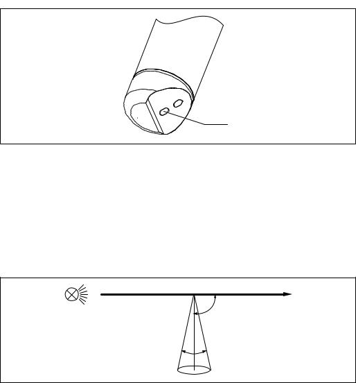
Installation marking
1
A0030820
10 Installation marking for sensor alignment
1Installation marking
The installation marking on the sensor is aligned opposite the optical system.
Align the sensor against the flow direction.
14 |
Endress+Hauser |

Turbimax CUS52D |
Installation |
|
|
5.2Mounting the sensor
5.2.1Measuring system
A complete measuring system comprises:
•Turbimax CUS52D turbidity sensor
•Liquiline CM44x multi-channel transmitter
•Assembly:
•CUA252 flow assembly (only possible for stainless steel sensor) or
•CUA262 flow assembly (only possible for stainless steel sensor) or
•Flexdip CYA112 assembly and Flexdip CYH112 holder or
•Retractable assembly, e.g. Cleanfit CUA451
•Or direct installation via pipe connection (only possible for stainless steel sensor)
•Clamp 2" or
•Varivent
1 |
2 |
3 |
4
A0030694
11 Example of measuring system with CUA252 flow assembly, for stainless steel sensor
1 Liquiline CM44x multi-channel transmitter
2 Turbimax CUS52D turbidity sensor
3 CUA252 flow assembly
4Direction of flow
Endress+Hauser |
15 |
Loading...