


 Loading...
KA01143D/06/EN/05.15
71301568
Products |
Solutions |
Services |
|
|
|
Brief Operating Instructions
Proline Promag P 100
Electromagnetic flowmeter
These Instructions are Brief Operating Instructions; they are not a substitute for the Operating Instructions pertaining to the device.
Detailed information about the device can be found in the Operating Instructions and the other documentation:
•On the CD-ROM supplied (not included in the delivery for all device versions).
•Available for all device versions via:
–Internet: www.endress.com/deviceviewer
–Smart phone/tablet: Endress+Hauser Operations App

Proline Promag P 100
ORDER CODE 00X00-XXXX0XX0XXX |
|
SER. NO.: X000X000000 |
|
TAG NO.: XXX000 |
|
Serial number |
|
www.endress.com/deviceviewer |
Endress+Hauser Operations App |
|
A0023555 |
2 |
Endress+Hauser |
Proline Promag P 100 |
Table of contents |
|
|
Table of contents
1 |
Document information . . . . . . . . . . . . . . . . . . . . . . . . . . . . . . . . . . . . . . . . . . . . . . . . . . . . . . . . . . . |
4 |
1.1 |
Symbols used . . . . . . . . . . . . . . . . . . . . . . . . . . . . . . . . . . . . . . . . . . . . . . . . . . . . . . . . . . . . . . . . . . . . . . . . |
4 |
2 |
Basic safety instructions . . . . . . . . . . . . . . . . . . . . . . . . . . . . . . . . . . . . . . . . . . . . . . . . . . . . . . . . . |
6 |
2.1 |
Requirements for the personnel . . . . . . . . . . . . . . . . . . . . . . . . . . . . . . . . . . . . . . . . . . . . . . . . . . . . . . . . . . . |
6 |
2.2 |
Designated use . . . . . . . . . . . . . . . . . . . . . . . . . . . . . . . . . . . . . . . . . . . . . . . . . . . . . . . . . . . . . . . . . . . . . . . |
6 |
2.3 |
Workplace safety . . . . . . . . . . . . . . . . . . . . . . . . . . . . . . . . . . . . . . . . . . . . . . . . . . . . . . . . . . . . . . . . . . . . . . |
7 |
2.4 |
Operational safety . . . . . . . . . . . . . . . . . . . . . . . . . . . . . . . . . . . . . . . . . . . . . . . . . . . . . . . . . . . . . . . . . . . . . |
7 |
2.5 |
Product safety . . . . . . . . . . . . . . . . . . . . . . . . . . . . . . . . . . . . . . . . . . . . . . . . . . . . . . . . . . . . . . . . . . . . . . . . |
7 |
2.6 |
IT security . . . . . . . . . . . . . . . . . . . . . . . . . . . . . . . . . . . . . . . . . . . . . . . . . . . . . . . . . . . . . . . . . . . . . . . . . . . |
8 |
3 |
Product description . . . . . . . . . . . . . . . . . . . . . . . . . . . . . . . . . . . . . . . . . . . . . . . . . . . . . . . . . . . . . . |
9 |
3.1 |
Product design . . . . . . . . . . . . . . . . . . . . . . . . . . . . . . . . . . . . . . . . . . . . . . . . . . . . . . . . . . . . . . . . . . . . . . . |
9 |
4 |
Incoming acceptance and product identification . . . . . . . . . . . . . . . . . . . . . . . . . . . . . . . . . |
11 |
4.1 |
Incoming acceptance . . . . . . . . . . . . . . . . . . . . . . . . . . . . . . . . . . . . . . . . . . . . . . . . . . . . . . . . . . . . . . . . . . |
11 |
4.2 |
Product identification . . . . . . . . . . . . . . . . . . . . . . . . . . . . . . . . . . . . . . . . . . . . . . . . . . . . . . . . . . . . . . . . . |
12 |
5 |
Storage and transport . . . . . . . . . . . . . . . . . . . . . . . . . . . . . . . . . . . . . . . . . . . . . . . . . . . . . . . . . . . |
12 |
5.1 |
Storage conditions . . . . . . . . . . . . . . . . . . . . . . . . . . . . . . . . . . . . . . . . . . . . . . . . . . . . . . . . . . . . . . . . . . . . |
12 |
5.2 |
Transporting the product . . . . . . . . . . . . . . . . . . . . . . . . . . . . . . . . . . . . . . . . . . . . . . . . . . . . . . . . . . . . . . . |
13 |
6 |
Mounting . . . . . . . . . . . . . . . . . . . . . . . . . . . . . . . . . . . . . . . . . . . . . . . . . . . . . . . . . . . . . . . . . . . . . . . |
14 |
6.1 |
Installation conditions . . . . . . . . . . . . . . . . . . . . . . . . . . . . . . . . . . . . . . . . . . . . . . . . . . . . . . . . . . . . . . . . . |
14 |
6.2 |
Mounting the measuring device . . . . . . . . . . . . . . . . . . . . . . . . . . . . . . . . . . . . . . . . . . . . . . . . . . . . . . . . . . |
18 |
6.3 |
Post-installation check . . . . . . . . . . . . . . . . . . . . . . . . . . . . . . . . . . . . . . . . . . . . . . . . . . . . . . . . . . . . . . . . . |
20 |
7 |
Electrical connection . . . . . . . . . . . . . . . . . . . . . . . . . . . . . . . . . . . . . . . . . . . . . . . . . . . . . . . . . . . . |
21 |
7.1 |
Connection conditions . . . . . . . . . . . . . . . . . . . . . . . . . . . . . . . . . . . . . . . . . . . . . . . . . . . . . . . . . . . . . . . . . |
21 |
7.2 |
Connecting the measuring device . . . . . . . . . . . . . . . . . . . . . . . . . . . . . . . . . . . . . . . . . . . . . . . . . . . . . . . . . |
29 |
7.3 |
Hardware settings . . . . . . . . . . . . . . . . . . . . . . . . . . . . . . . . . . . . . . . . . . . . . . . . . . . . . . . . . . . . . . . . . . . . |
33 |
7.4 |
Ensuring the degree of protection . . . . . . . . . . . . . . . . . . . . . . . . . . . . . . . . . . . . . . . . . . . . . . . . . . . . . . . . |
36 |
7.5 |
Post-connection check . . . . . . . . . . . . . . . . . . . . . . . . . . . . . . . . . . . . . . . . . . . . . . . . . . . . . . . . . . . . . . . . . |
37 |
8 |
Operation options . . . . . . . . . . . . . . . . . . . . . . . . . . . . . . . . . . . . . . . . . . . . . . . . . . . . . . . . . . . . . . |
38 |
8.1 |
Structure and function of the operating menu . . . . . . . . . . . . . . . . . . . . . . . . . . . . . . . . . . . . . . . . . . . . . . . . |
38 |
8.2 |
Access to the operating menu via the Web browser . . . . . . . . . . . . . . . . . . . . . . . . . . . . . . . . . . . . . . . . . . . . |
38 |
8.3 |
Access to the operating menu via the operating tool . . . . . . . . . . . . . . . . . . . . . . . . . . . . . . . . . . . . . . . . . . . |
42 |
9 |
System integration . . . . . . . . . . . . . . . . . . . . . . . . . . . . . . . . . . . . . . . . . . . . . . . . . . . . . . . . . . . . . . |
42 |
10 |
Commissioning . . . . . . . . . . . . . . . . . . . . . . . . . . . . . . . . . . . . . . . . . . . . . . . . . . . . . . . . . . . . . . . . . |
43 |
10.1 |
Function check . . . . . . . . . . . . . . . . . . . . . . . . . . . . . . . . . . . . . . . . . . . . . . . . . . . . . . . . . . . . . . . . . . . . . . |
43 |
10.2 |
Establishing a connection via FieldCare . . . . . . . . . . . . . . . . . . . . . . . . . . . . . . . . . . . . . . . . . . . . . . . . . . . . |
43 |
10.3 |
Configuring the device address via software . . . . . . . . . . . . . . . . . . . . . . . . . . . . . . . . . . . . . . . . . . . . . . . . . |
43 |
10.4 |
Configuring the measuring device . . . . . . . . . . . . . . . . . . . . . . . . . . . . . . . . . . . . . . . . . . . . . . . . . . . . . . . . |
44 |
10.5 |
Defining the tag name . . . . . . . . . . . . . . . . . . . . . . . . . . . . . . . . . . . . . . . . . . . . . . . . . . . . . . . . . . . . . . . . . |
44 |
10.6 |
Protecting settings from unauthorized access . . . . . . . . . . . . . . . . . . . . . . . . . . . . . . . . . . . . . . . . . . . . . . . . |
44 |
11 |
Diagnostic information . . . . . . . . . . . . . . . . . . . . . . . . . . . . . . . . . . . . . . . . . . . . . . . . . . . . . . . . . |
47 |
Endress+Hauser |
3 |

Document information |
Proline Promag P 100 |
|
|
1Document information
1.1Symbols used
1.1.1Safety symbols
Symbol Meaning
DANGER!
 DANGER This symbol alerts you to a dangerous situation. Failure to avoid this situation will result in serious or fatal injury.
WARNING!
WARNING This symbol alerts you to a dangerous situation. Failure to avoid this situation can result in serious or fatal injury.
CAUTION!
 CAUTION This symbol alerts you to a dangerous situation. Failure to avoid this situation can result in minor or medium injury.
NOTE!
NOTICE This symbol contains information on procedures and other facts which do not result in personal injury.
1.1.2Electrical symbols
Symbol Meaning
Direct current
A terminal to which DC voltage is applied or through which direct current flows.
Alternating current
A terminal to which alternating voltage is applied or through which alternating current flows.
Direct current and alternating current
•A terminal to which alternating voltage or DC voltage is applied.
•A terminal through which alternating current or direct current flows.
Ground connection
A grounded terminal which, as far as the operator is concerned, is grounded via a grounding system.
Protective ground connection
A terminal which must be connected to ground prior to establishing any other connections.
Equipotential connection
A connection that has to be connected to the plant grounding system: This may be a potential equalization line or a star grounding system depending on national or company codes of practice.
4 |
Endress+Hauser |
Proline Promag P 100 |
Document information |
|
|
1.1.3Tool symbols
Symbol |
Meaning |
|
Allen key |
Open-ended wrench
1.1.4Symbols for certain types of information
Symbol Meaning
Permitted
Indicates procedures, processes or actions that are permitted.
Preferred
Indicates procedures, processes or actions that are preferred.
Forbidden
Indicates procedures, processes or actions that are forbidden.
Tip
Indicates additional information.
Reference to documentation
Refers to the corresponding device documentation.
Reference to page
Refers to the corresponding page number.
Reference to graphic
Refers to the corresponding graphic number and page number.
 ,
,  ,
,  … Series of steps
Result of a sequence of actions
Visual inspection
1.1.5Symbols in graphics
|
Symbol |
Meaning |
|||||
|
|
|
|
|
|
|
|
1, 2, 3,... |
Item numbers |
||||||
|
|
|
|
|
|
|
|
|
|
, |
|
, |
|
… |
Series of steps |
|
|
|
|
||||
|
|
||||||
A, B, C, ... |
Views |
||||||
|
|
||||||
A-A, B-B, C-C, ... |
Sections |
||||||
|
|
|
|
|
|
|
|
|
|
|
|
|
|
|
Flow direction |
|
|
|
|
|
|
|
|
Endress+Hauser |
5 |
Basic safety instructions |
Proline Promag P 100 |
|
|
|
|
|
|
|
Symbol |
|
Meaning |
|
|
|
- |
|
Hazardous area |
|
Indicates a hazardous area. |
|
|
|
|
|
|
|
. |
|
Safe area (non-hazardous area) |
|
Indicates the non-hazardous area. |
|
|
|
|
2Basic safety instructions
2.1Requirements for the personnel
The personnel must fulfill the following requirements for its tasks:
Trained, qualified specialists must have a relevant qualification for this specific function and task
Are authorized by the plant owner/operator
Are familiar with federal/national regulations
Before beginning work, the specialist staff must have read and understood the instructions in the Operating Instructions and supplementary documentation as well as in the certificates (depending on the application)
Following instructions and basic conditions
2.2Designated use
Application and media
Depending on the version ordered, the measuring device can also measure potentially explosive, flammable, poisonous and oxidizing media.
Measuring devices for use in hazardous areas, in hygienic applications or in applications where there is an increased risk due to process pressure, are labeled accordingly on the nameplate.
To ensure that the measuring device remains in proper condition for the operation time:
Only use the measuring device in full compliance with the data on the nameplate and the general conditions listed in the Operating Instructions and supplementary documentation.
Based on the nameplate, check whether the ordered device is permitted for the intended use in the hazardous area (e.g. explosion protection, pressure vessel safety).
Use the measuring device only for media against which the process-wetted materials are adequately resistant.
If the measuring device is not operated at atmospheric temperature, compliance with the relevant basic conditions specified in the associated device documentation is absolutely essential: "Device documentation" section (Verweisziel existiert nicht, aber @y.link.required='true').
Incorrect use
Non-designated use can compromise safety. The manufacturer is not liable for damage caused by improper or non-designated use.
6 |
Endress+Hauser |

Proline Promag P 100 |
Basic safety instructions |
|
|
LWARNING
Danger of breakage of the sensor due to corrosive or abrasive fluids!
Verify the compatibility of the process fluid with the sensor material.
Ensure the resistance of all fluid-wetted materials in the process.
Observe the specified pressure and temperature range.
Verification for borderline cases:
For special fluids and fluids for cleaning, Endress+Hauser is glad to provide assistance in verifying the corrosion resistance of fluid-wetted materials, but does not accept any warranty or liability as minute changes in the temperature, concentration or level of contamination in the process can alter the corrosion resistance properties.
Residual risks
The external surface temperature of the housing can increase by max. 10 K due to the power consumption of the electronic components. Hot process fluids passing through the measuring device will further increase the surface temperature of the housing. The surface of the sensor, in particular, can reach temperatures which are close to the fluid temperature.
Possible burn hazard due to fluid temperatures!
For elevated fluid temperature, ensure protection against contact to prevent burns.
2.3Workplace safety
For work on and with the device:
Wear the required personal protective equipment according to federal/national regulations.
For welding work on the piping:
Do not ground the welding unit via the measuring device.
If working on and with the device with wet hands:
It is recommended to wear gloves on account of the higher risk of electric shock.
2.4Operational safety
Risk of injury.
Operate the device in proper technical condition and fail-safe condition only.
The operator is responsible for interference-free operation of the device.
2.5Product safety
This measuring device is designed in accordance with good engineering practice to meet state- of-the-art safety requirements, has been tested, and left the factory in a condition in which it is safe to operate.
It meets general safety standards and legal requirements. It also complies with the EC directives listed in the device-specific EC Declaration of Conformity. Endress+Hauser confirms this by affixing the CE mark to the device.
Endress+Hauser |
7 |
Basic safety instructions |
Proline Promag P 100 |
|
|
2.6IT security
We only provide a warranty if the device is installed and used as described in the Operating Instructions. The device is equipped with security mechanisms to protect it against any inadvertent changes to the device settings.
IT security measures in line with operators' security standards and designed to provide additional protection for the device and device data transfer must be implemented by the operators themselves.
8 |
Endress+Hauser |

Proline Promag P 100 |
Product description |
|
|
3Product description
3.1Product design
3.1.1Device version with HART, EtherNet/IP and PROFIBUS DP communication types
|
5 |
4 |
6 |
|
|
|
7 |
3 |
|
2
1
A0023153
1 Important components of a measuring device
1Sensor
2Transmitter housing
3 Main electronics module
4Transmitter housing cover
Endress+Hauser |
9 |

Product description |
Proline Promag P 100 |
|
|
5 Transmitter housing cover (version for optional onsite display)
6Onsite display (optional)
7Main electronics module (with bracket for optional onsite display)
3.1.2Device version with Modbus RS485 communication types
4
3
2
1
A0017609
2 Important components of a measuring device
1Sensor
2Transmitter housing
3 Main electronics module
4Transmitter housing cover
10 |
Endress+Hauser |
Proline Promag P 100 |
Incoming acceptance and product identification |
|
|
4Incoming acceptance and product identification
4.1Incoming acceptance
|
Are the order codes on the |
|
delivery note (1) and the |
|
product sticker (2) identical? |
1 |
1 |
+ |
+ |
2 |
2 |
Are the goods undamaged?
Do the nameplate data match the ordering information on the delivery note?
Is the CD-ROM with the Technical Documentation (depends on device version) and documents present?
• If one of the conditions is not satisfied, contact your Endress+Hauser Sales Center.
•Depending on the device version, the CD-ROM might not be part of the delivery! The Technical Documentation is available via the Internet or via the Endress+Hauser Operations App.
Endress+Hauser |
11 |
Storage and transport |
Proline Promag P 100 |
|
|
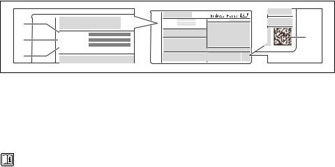
4.2Product identification
The following options are available for identification of the measuring device:
•Nameplate specifications
•Order code with breakdown of the device features on the delivery note
•Enter serial numbers from nameplates in W@M Device Viewer (www.endress.com/deviceviewer): All information about the measuring device is displayed.
•Enter the serial number from the nameplates into the Endress+Hauser Operations App or scan the 2-D matrix code (QR code) on the nameplate with the Endress+Hauser Operations App: all the information for the measuring device is displayed.
1 |
|
ORDER CODE: |
|
|
SER. NO.: |
||
|
EXT. ORD. CD.: |
||
|
ORDER CODE: |
4 |
|
2 |
SER. NO.: |
||
|
|||
|
EXT. ORD. CD.: |
|
|
3 |
|
|
|
|
|
A0021952 |
3 Example of a nameplate
1Order code
2Serial number (Ser. no.)
3 Extended order code (Ext. ord. cd.)
42-D matrix code (QR code)
For detailed information on the breakdown of the specifications on the nameplate, see the Operating Instructions for the device .
5Storage and transport
5.1Storage conditions
Observe the following notes for storage:
•Store in original packaging.
•Do not remove protective covers or protective caps installed on process connections.
•Protect from direct sunlight.
•Select a storage location where moisture cannot collect in the measuring device.
•Store in a dry and dust-free place.
•Do not store outdoors.
•Storage temperature→ 14
12 |
Endress+Hauser |

Proline Promag P 100 |
Storage and transport |
|
|
5.2Transporting the product
LWARNING
Center of gravity of the measuring device is higher than the suspension points of the webbing slings.
Risk of injury if the measuring device slips.
Secure the measuring device from rotating or slipping.
Observe the weight specified on the packaging (stick-on label).
Observe the transport instructions on the stick-on label on the electronics compartment cover.
A0015606
• Transport the measuring device to the measuring point in the original packaging.
•Do not remove protective covers or protective caps installed on process connections. They prevent mechanical damage to the sealing surfaces and contamination in the measuring tube.
A0015604 |
Endress+Hauser |
13 |

Mounting |
Proline Promag P 100 |
|
|
6Mounting
6.1Installation conditions
6.1.1 Mounting position
Mounting location
h
A0023343
h ≥ 2 × DN
Installation in down pipes
Install a siphon with a vent valve downstream of the sensor in down pipes whose length h ≥ 5 m (16.4 ft). This precaution is to avoid low pressure and the consequent risk of damage to
the measuring tube. This measure also prevents the system losing prime.
 1
1  2
2
h
A0017064
4 Installation in a down pipe 1 Vent valve
2Pipe siphon
hLength of down pipe
14 |
Endress+Hauser |

Proline Promag P 100 |
Mounting |
|
|
Installation in partially filled pipes
A partially filled pipe with a gradient necessitates a drain-type configuration. The empty pipe detection (EPD) function offers additional protection by detecting empty or partially filled pipes.
 2×DN ≥
5×DN ≥
A0017063
Orientation
The direction of the arrow on the sensor nameplate helps you to install the sensor according to the flow direction.
An optimum orientation position helps avoid gas and air accumulations and deposits in the measuring tube.
Vertical
A0015591
This is the optimum for self-emptying piping systems and for use in conjunction with empty pipe detection.
Endress+Hauser |
15 |
Loading...