


 Loading...
TI01046D/06/EN/07.17
71380241
Products |
Solutions |
Services |
|
|
|
Technical Information
Proline Promag W 400
Electromagnetic flowmeter
Sensor with EN ISO 12944 corrosion protection and state of the art transmitter for Water & Wastewater
Application
•The bidirectional measuring principle is virtually independent of pressure, density, temperature and viscosity
•The specialist in the water and wastewater industry for the most demanding applications
Device properties
•International drinking water approvals
•Degree of protection IP68 (Type 6P enclosure)
•Approved for custody transfer to MI-001/OIML R49
•Transmitter housing made of durable polycarbonate or aluminum
•WLAN access
•Integrated data logger: measured values monitoring
Your benefits
•For direct underground installation or permanent underwater use
•Safe, reliable long-term operation – robust and completely welded sensor
•Energy-saving flow measurement – no pressure loss due to cross-section constriction
•Maintenance-free – no moving parts
•Safe operation – no need to open the device due to display with touch control, background lighting
•Time saving local operation without additional software and hardware – integrated web server
•Integrated verification – Heartbeat Technology

Proline Promag W 400
Table of contents
About this document . . . . . . . . . . . . . . . . . . . . . . . . 4
Symbols used . . . . . . . . . . . . . . . . . . . . . . . . . . . . . . . . 4
Function and system design . . . . . . . . . . . . . . . . . . . 5
Measuring principle . . . . . . . . . . . . . . . . . . . . . . . . . . . . 5 Measuring system . . . . . . . . . . . . . . . . . . . . . . . . . . . . . 6 Equipment architecture . . . . . . . . . . . . . . . . . . . . . . . . . 7 Safety . . . . . . . . . . . . . . . . . . . . . . . . . . . . . . . . . . . . . 7
Input . . . . . . . . . . . . . . . . . . . . . . . . . . . . . . . . . . . . . 8
Measured variable . . . . . . . . . . . . . . . . . . . . . . . . . . . . . 8 Measuring range . . . . . . . . . . . . . . . . . . . . . . . . . . . . . . 8 Operable flow range . . . . . . . . . . . . . . . . . . . . . . . . . . . 12 Input signal . . . . . . . . . . . . . . . . . . . . . . . . . . . . . . . . 12
Output . . . . . . . . . . . . . . . . . . . . . . . . . . . . . . . . . . 12
Output signal . . . . . . . . . . . . . . . . . . . . . . . . . . . . . . . 12 Signal on alarm . . . . . . . . . . . . . . . . . . . . . . . . . . . . . . 14 Low flow cut off . . . . . . . . . . . . . . . . . . . . . . . . . . . . . 15 Galvanic isolation . . . . . . . . . . . . . . . . . . . . . . . . . . . . 15 Protocol-specific data . . . . . . . . . . . . . . . . . . . . . . . . . . 16
Power supply . . . . . . . . . . . . . . . . . . . . . . . . . . . . . |
20 |
Terminal assignment . . . . . . . . . . . . . . . . . . . . . . . . . . |
20 |
Pin assignment, device plug . . . . . . . . . . . . . . . . . . . . . . |
22 |
Supply voltage . . . . . . . . . . . . . . . . . . . . . . . . . . . . . . |
23 |
Power consumption . . . . . . . . . . . . . . . . . . . . . . . . . . . |
23 |
Current consumption . . . . . . . . . . . . . . . . . . . . . . . . . . |
23 |
Power supply failure . . . . . . . . . . . . . . . . . . . . . . . . . . |
23 |
Electrical connection . . . . . . . . . . . . . . . . . . . . . . . . . . |
24 |
Potential equalization . . . . . . . . . . . . . . . . . . . . . . . . . |
28 |
terminals . . . . . . . . . . . . . . . . . . . . . . . . . . . . . . . . . . |
30 |
Cable entries . . . . . . . . . . . . . . . . . . . . . . . . . . . . . . . |
30 |
Cable specification . . . . . . . . . . . . . . . . . . . . . . . . . . . . |
30 |
Performance characteristics . . . . . . . . . . . . . . . . . . 33
Reference operating conditions . . . . . . . . . . . . . . . . . . . 33 Maximum measured error . . . . . . . . . . . . . . . . . . . . . . . 33 Repeatability . . . . . . . . . . . . . . . . . . . . . . . . . . . . . . . 34 Influence of ambient temperature . . . . . . . . . . . . . . . . . 34
Installation . . . . . . . . . . . . . . . . . . . . . . . . . . . . . . . 35
Mounting location . . . . . . . . . . . . . . . . . . . . . . . . . . . . 35 Orientation . . . . . . . . . . . . . . . . . . . . . . . . . . . . . . . . 36 Inlet and outlet runs . . . . . . . . . . . . . . . . . . . . . . . . . . 37 Adapters . . . . . . . . . . . . . . . . . . . . . . . . . . . . . . . . . . 37 Length of connecting cable . . . . . . . . . . . . . . . . . . . . . . 38 Mounting the transmitter housing . . . . . . . . . . . . . . . . . 39 Special mounting instructions . . . . . . . . . . . . . . . . . . . . 39
Environment . . . . . . . . . . . . . . . . . . . . . . . . . . . . . . 40
Ambient temperature range . . . . . . . . . . . . . . . . . . . . . 40 Storage temperature . . . . . . . . . . . . . . . . . . . . . . . . . . 41 Atmosphere . . . . . . . . . . . . . . . . . . . . . . . . . . . . . . . . 41 Degree of protection . . . . . . . . . . . . . . . . . . . . . . . . . . 41 Vibration resistance . . . . . . . . . . . . . . . . . . . . . . . . . . . 41 Shock resistance . . . . . . . . . . . . . . . . . . . . . . . . . . . . . 41
Impact resistance . . . . . . . . . . . . . . . . . . . . . . . . . . . . |
42 |
Mechanical load . . . . . . . . . . . . . . . . . . . . . . . . . . . . . |
42 |
Electromagnetic compatibility (EMC) . . . . . . . . . . . . . . . |
42 |
Process . . . . . . . . . . . . . . . . . . . . . . . . . . . . . . . . . . 42
Medium temperature range . . . . . . . . . . . . . . . . . . . . . . 42 Conductivity . . . . . . . . . . . . . . . . . . . . . . . . . . . . . . . . 42 Pressure-temperature ratings . . . . . . . . . . . . . . . . . . . . 42 Pressure tightness . . . . . . . . . . . . . . . . . . . . . . . . . . . . 45 Flow limit . . . . . . . . . . . . . . . . . . . . . . . . . . . . . . . . . 45 Pressure loss . . . . . . . . . . . . . . . . . . . . . . . . . . . . . . . 45 System pressure . . . . . . . . . . . . . . . . . . . . . . . . . . . . . 46 Vibrations . . . . . . . . . . . . . . . . . . . . . . . . . . . . . . . . . 46
Custody transfer mode . . . . . . . . . . . . . . . . . . . . . . 47
Mechanical construction . . . . . . . . . . . . . . . . . . . . 47
Dimensions in SI units . . . . . . . . . . . . . . . . . . . . . . . . . 47 Dimensions in US units . . . . . . . . . . . . . . . . . . . . . . . . . 71 Weight . . . . . . . . . . . . . . . . . . . . . . . . . . . . . . . . . . . 93 Measuring tube specification . . . . . . . . . . . . . . . . . . . . 111 Materials . . . . . . . . . . . . . . . . . . . . . . . . . . . . . . . . . 113 Fitted electrodes . . . . . . . . . . . . . . . . . . . . . . . . . . . . 115 Process connections . . . . . . . . . . . . . . . . . . . . . . . . . . 115 Surface roughness . . . . . . . . . . . . . . . . . . . . . . . . . . . 116
Operability . . . . . . . . . . . . . . . . . . . . . . . . . . . . . . 116
Operating concept . . . . . . . . . . . . . . . . . . . . . . . . . . . 116 Languages . . . . . . . . . . . . . . . . . . . . . . . . . . . . . . . . 116 Local display . . . . . . . . . . . . . . . . . . . . . . . . . . . . . . . 116 Remote operation . . . . . . . . . . . . . . . . . . . . . . . . . . . 117 Service interface . . . . . . . . . . . . . . . . . . . . . . . . . . . . 119 Supported operating tools . . . . . . . . . . . . . . . . . . . . . . 120 HistoROM data management . . . . . . . . . . . . . . . . . . . . 122
Certificates and approvals . . . . . . . . . . . . . . . . . . 123
CE mark . . . . . . . . . . . . . . . . . . . . . . . . . . . . . . . . . . 123 C-Tick symbol . . . . . . . . . . . . . . . . . . . . . . . . . . . . . . 123 Ex approval . . . . . . . . . . . . . . . . . . . . . . . . . . . . . . . 123 Drinking water approval . . . . . . . . . . . . . . . . . . . . . . . 123 HART certification . . . . . . . . . . . . . . . . . . . . . . . . . . . 123 Certification PROFIBUS . . . . . . . . . . . . . . . . . . . . . . . . 123 Modbus RS485 certification . . . . . . . . . . . . . . . . . . . . . 123 EtherNet/IP certification . . . . . . . . . . . . . . . . . . . . . . . 123 Radio approval . . . . . . . . . . . . . . . . . . . . . . . . . . . . . 123 Measuring instrument approval . . . . . . . . . . . . . . . . . . 123 Other standards and guidelines . . . . . . . . . . . . . . . . . . 124
Ordering information . . . . . . . . . . . . . . . . . . . . . . 124
Product generation index . . . . . . . . . . . . . . . . . . . . . . 124
Application packages . . . . . . . . . . . . . . . . . . . . . . 125
Cleaning . . . . . . . . . . . . . . . . . . . . . . . . . . . . . . . . . 125 Diagnostics functions . . . . . . . . . . . . . . . . . . . . . . . . . 125 Heartbeat Technology . . . . . . . . . . . . . . . . . . . . . . . . 125
2 |
Endress+Hauser |

Proline Promag W 400
Accessories . . . . . . . . . . . . . . . . . . . . . . . . . . . . . . 125
Device-specific accessories . . . . . . . . . . . . . . . . . . . . . . 126 Communication-specific accessories . . . . . . . . . . . . . . . 126 Service-specific accessories . . . . . . . . . . . . . . . . . . . . . 127 System components . . . . . . . . . . . . . . . . . . . . . . . . . . 127
Supplementary documentation . . . . . . . . . . . . . . 128
Standard documentation . . . . . . . . . . . . . . . . . . . . . . . 128 Supplementary device-dependent documentation . . . . . . 128
Registered trademarks . . . . . . . . . . . . . . . . . . . . . 129
Endress+Hauser |
3 |

Proline Promag W 400
About this document
Symbols used |
Electrical symbols |
|
||
|
|
|
|
|
|
Symbol |
Meaning |
||
|
|
|
|
|
|
|
|
|
Direct current |
|
|
|
|
|
|
|
|
|
Alternating current |
|
|
|
|
|
|
|
|
|
Direct current and alternating current |
|
|
|
|
|
|
|
|
|
|
|
|
|
|
Ground connection |
|
|
|
|
A grounded terminal which, as far as the operator is concerned, is grounded via a |
|
|
|
|
grounding system. |
|
|
|
|
|
|
|
|
|
Protective Earth (PE) |
|
|
|
|
A terminal which must be connected to ground prior to establishing any other |
|
|
|
|
connections. |
|
|
|
|
The ground terminals are situated inside and outside the device: |
|
|
|
|
• Inner ground terminal: Connects the protectiv earth to the mains supply. |
|
|
|
|
• Outer ground terminal: Connects the device to the plant grounding system. |
|
|
|
|
|
Communication symbols
Symbol Meaning
Wireless Local Area Network (WLAN)
Communication via a wireless, local network.
Bluetooth
Wireless data transmission between devices over a short distance.
LED
Light emitting diode is off.
LED
Light emitting diode is on.
LED
Light emitting diode is flashing.
Symbols for certain types of information
Symbol Meaning
Permitted
Procedures, processes or actions that are permitted.
Preferred
Procedures, processes or actions that are preferred.
Forbidden
Procedures, processes or actions that are forbidden.
Tip
Indicates additional information.
Reference to documentation.
A |
Reference to page. |
Reference to graphic.
Visual inspection.
4 |
Endress+Hauser |
Proline Promag W 400
Symbols in graphics
|
Symbol |
Meaning |
|||||
|
|
|
|
|
|
|
|
1, 2, 3, ... |
Item numbers |
||||||
|
|
|
|
|
|
|
|
|
|
, |
|
, |
|
, … |
Series of steps |
|
1. |
2. |
3. |
||||
|
|
|
|||||
|
A, B, C, ... |
Views |
|||||
|
|
||||||
A-A, B-B, C-C, ... |
Sections |
||||||
-Hazardous area
. |
Safe area (non-hazardous area) |
|
|
|
|
|
Flow direction |
|
Function and system design |
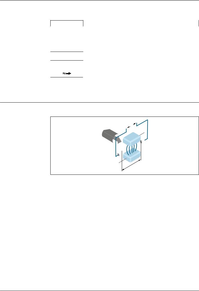
Measuring principle |
Following Faraday's law of magnetic induction, a voltage is induced in a conductor moving through a |
|
magnetic field. |
|
UE |
|
I |
|
V |
|
B |
|
I |
|
L |
A0028962
Ue |
Induced voltage |
B |
Magnetic induction (magnetic field) |
LElectrode spacing
ICurrent
vFlow velocity
In the electromagnetic measuring principle, the flowing medium is the moving conductor. The voltage induced (Ue) is proportional to the flow velocity (v) and is supplied to the amplifier by means of two measuring electrodes. The flow volume (Q) is calculated via the pipe cross-section (A). The DC magnetic field is created through a switched direct current of alternating polarity.
Formulae for calculation
•Induced voltage Ue = B · L · v
•Volume flow Q = A · v
Endress+Hauser |
5 |

Proline Promag W 400
Measuring system |
The device consists of a transmitter and a sensor. |
Two device versions are available:
•Compact version – transmitter and sensor form a mechanical unit.
•Remote version - transmitter and sensor are mounted in separate locations.
Transmitter
Promag 400 |
Device versions and materials |
|
|
• Compact version: compact housing |
|
|
|
– Polycarbonate plastic |
|
|
– Aluminum, AlSi10Mg, coated |
|
• Remote version: wall-mount housing |
|
|
|
– Polycarbonate plastic |
|
|
– Aluminum, AlSi10Mg, coated |
|
Configuration: |
|
A0017117 |
• |
External operation via four-line, illuminated local display with touch |
|
|
control and guided menus ("Make-it-run" wizards) for applications |
|
• |
Via operating tools (e.g. FieldCare) |
|
• Via Web browser (e.g. Microsoft Internet Explorer) |
|
|
• Also for device version with EtherNet/IP output: |
|
|
|
– Via Add-on Profile Level 3 for automation system from Rockwell |
|
|
Automation |
|
|
– Via Electronic Data Sheet (EDS) |
|
• Also for device version with PROFIBUS DP output: |
|
|
|
Via PDM driver for Siemens automation system |
Sensor
Promag W
Fixed flange: DN 25 to 300 (1 to 12")
A0017040
Fixed flange: DN 25 to 300 (1 to 12")
A0022673
Fixed flange: DN 350 to 2000 (14 to 78")
•Nominal diameter range: DN 25 to 2000 (1 to 78")
•Materials:
–Sensor housing: aluminum, AlSi10Mg, coated; carbon steel with protective varnish
–Sensor connection housing (standard): aluminum, AlSi10Mg, coated Sensor connection housing (option): polycarbonate
–Measuring tubes 1):
DN 25 to 300 (1 to 12"): stainless steel, 1.4301/1.4306/304/304L DN 350 to 2000 (14 to 78"): stainless steel, 1.4301/304
–Liner: hard rubber, polyurethane
–Electrodes: stainless steel, 1.4435 (316L); Alloy C22, 2.4602 (UNS N06022); tantalum
–Process connections:
Stainless steel, 1.4404/1.4571/F316L
Carbon steel, A105/A181/A515(70)/FE410WB/P250GH/ P235 GH/P265GH/S235JRG2/S235JR+N/S275JR
–Seals: as per DIN EN 1514-1 Form IBC
–Ground disks: stainless steel, 1.4435 (316L); Alloy C22, 2.4602 (UNS N06022); tantalum
A0017041
1)For carbon steel flange material with Al/Zn protective coating (DN 25 to 300 (1 to 12")), protective varnish (IP68) (DN 50 to 300 (2 to 12")) or protective varnish ≥ DN 350 (14")
6 |
Endress+Hauser |

Proline Promag W 400 |
|
|
|
Equipment architecture |
|
|
|
1 |
|
|
|
2 |
3 |
4 |
5 |
7 |
|
|
|
8 |
|
|
|
6 |
|
|
|
|
|
|
A0021560 |
1 Possibilities for integrating measuring devices into a system |
|
|
|
1Control system (e.g. PLC)
2 |
EtherNet/IP |
3 |
PROFIBUS DP |
4Modbus RS485
5 4-20 mA HART, pulse/frequency/switch output
6Non-hazardous area
7Non-hazardous area and Zone 2/Div. 2
Safety |
IT security |
We only provide a warranty if the device is installed and used as described in the Operating Instructions. The device is equipped with security mechanisms to protect it against any inadvertent changes to the device settings.
IT security measures in line with operators' security standards and designed to provide additional protection for the device and device data transfer must be implemented by the operators themselves.
Device-specific IT security
The device offers a range of specific functions to support protective measures on the operator's side. These functions can be configured by the user and guarantee greater in-operation safety if used correctly. An overview of the most important functions is provided in the following section.
Protecting access via hardware write protection
Write access to the device parameters via the local display or operating tool (e.g. FieldCare, DeviceCare) can be disabled via a write protection switch (DIP switch on the motherboard). When hardware write protection is enabled, only read access to the parameters is possible.
Hardware write protection is disabled when the device is delivered.
Protecting access via a password
Different passwords are available to protect write access to the device parameters or access to the device via the WLAN interface.
•User-specific access code
Protect write access to the device parameters via the local display, Web browser or operating tool (e.g. FieldCare, DeviceCare). Access authorization is clearly regulated through the use of a userspecific access code.
•WLAN passphrase
The network key protects a connection between an operating unit (e.g. notebook or tablet) and the device via the WLAN interface which can be ordered as an option.
User-specific access code
Write access to the device parameters via the local display or operating tool (e.g. FieldCare,
DeviceCare) can be protected by the modifiable, user-specific access code.
Endress+Hauser |
7 |

Proline Promag W 400
WLAN passphrase
A connection between an operating unit (e.g. notebook or tablet) and the device via the WLAN interface which can be ordered as an option is protected by the network key. The WLAN authentication of the network key complies with the IEEE 802.11 standard.
When the device is delivered, the network key is pre-defined depending on the device. It can be changed via the WLAN settings submenu in the WLAN passphrase parameter.
General notes on the use of passwords
• The access code and network key supplied with the device should be changed during commissioning.
• Follow the general rules for generating a secure password when defining and managing the access code or network key.
• The user is responsible for the management and careful handling of the access code and network key.
Access via fieldbus
When communicating via fieldbus, access to the device parameters can be restricted to "Read only" access. The option can be changed in the Fieldbus writing access parameter.
This does not affect cyclic measured value transmission to the higher-order system, which is always guaranteed.
For detailed information, see the "Description of Device Parameters" document pertaining to the device → 128
|
Access via Web server |
|
|
The device can be operated and configured via a Web browser with the integrated Web server. The |
|
|
connection is via the service interface (CDI-RJ45) or the WLAN interface. For device versions with |
|
|
the EtherNet/IP and PROFINET communication protocols, the connection can also be established via |
|
|
the terminal connection for signal transmission with EtherNet/IP or PROFINET (RJ45 connector). |
|
|
The Web server is enabled when the device is delivered. The Web server can be disabled if necessary |
|
|
(e.g. after commissioning) via the Web server functionality parameter. |
|
|
The device and status information can be hidden on the login page. This prevents unauthorized |
|
|
access to the information. |
|
|
|
For detailed information, see the "Description of Device Parameters" document pertaining to the |
|
|
|
|
|
device → 128 |
|
|
|
|
Input |
|
|
|
|
Measured variable |
Direct measured variables |
|
|
• Volume flow (proportional to induced voltage) |
|
|
• Electrical conductivity |
|
|
|
In custody transfer: only volume flow |
|
Calculated measured variables |
|
|
Mass flow |
|
|
|
|
Measuring range |
Typically v = 0.01 to 10 m/s (0.03 to 33 ft/s) with the specified accuracy |
|
|
Electrical conductivity: ≥ 5 μS/cm for liquids in general |
|
8 |
Endress+Hauser |

Proline Promag W 400
Flow characteristic values in SI units 1)
Nominal |
Recommended |
|
Factory settings |
|
|
|||||
diameter |
flow |
|
|
|
||||||
|
|
|
|
|
|
|||||
|
|
|
min./max. full scale value |
Full scale value current |
|
Pulse value |
|
Low flow cut off |
||
|
|
|
|
|
||||||
|
|
|
output |
|
|
|
||||
|
|
|
(v ~ 0.3/10 m/s) |
|
|
(~ 2 pulse/s) |
|
(v ~ 0.04 m/s) |
||
|
|
|
(v ~ 2.5 m/s) |
|
|
|
||||
|
|
|
|
|
|
|
|
|
|
|
[mm] |
|
[in] |
[m3/h] |
[m3/h] |
|
|
[m3] |
|
[m3/h] |
|
|
|
|
|
|||||||
25 |
|
1 |
9 to 300 dm3/min |
75 dm3/min |
|
|
0.5 dm3 |
|
1 dm3/min |
|
32 |
|
– |
15 to 500 dm3/min |
125 dm3/min |
|
|
1 dm3 |
|
2 dm3/min |
|
40 |
|
1 ½ |
25 to 700 dm3/min |
200 dm3/min |
|
|
1.5 dm3 |
|
3 dm3/min |
|
50 |
|
2 |
35 to 1 100 dm3/min |
300 dm3/min |
|
|
2.5 dm3 |
|
5 dm3/min |
|
65 |
|
– |
60 to 2 000 dm3/min |
500 dm3/min |
|
|
5 dm3 |
|
8 dm3/min |
|
80 |
|
3 |
90 to 3 000 dm3/min |
750 dm3/min |
|
|
5 dm3 |
|
12 dm3/min |
|
100 |
|
4 |
145 to 4 700 dm3/min |
1 200 dm3/min |
|
|
10 dm3 |
|
20 dm3/min |
|
125 |
|
– |
220 to 7 500 dm3/min |
1 850 dm3/min |
|
|
15 dm3 |
|
30 dm3/min |
|
150 |
|
6 |
20 to 600 |
150 |
|
|
0.025 |
|
2.5 |
|
|
|
|
|
|
|
|
|
|
|
|
200 |
|
8 |
35 to |
1 100 |
300 |
|
|
0.05 |
|
5 |
|
|
|
|
|
|
|
|
|
|
|
250 |
|
10 |
55 to |
1 700 |
500 |
|
|
0.05 |
|
7.5 |
|
|
|
|
|
|
|
|
|
|
|
300 |
|
12 |
80 to |
2 400 |
750 |
|
|
0.1 |
|
10 |
|
|
|
|
|
|
|
|
|
|
|
350 |
|
14 |
110 to 3 300 |
1 000 |
|
|
0.1 |
|
15 |
|
|
|
|
|
|
|
|
|
|
|
|
375 |
|
15 |
140 to 4 200 |
1 200 |
|
|
0.15 |
|
20 |
|
|
|
|
|
|
|
|
|
|
|
|
400 |
|
16 |
140 to 4 200 |
1 200 |
|
|
0.15 |
|
20 |
|
|
|
|
|
|
|
|
|
|
|
|
450 |
|
18 |
180 to 5 400 |
1 500 |
|
|
0.25 |
|
25 |
|
|
|
|
|
|
|
|
|
|
|
|
500 |
|
20 |
220 to 6 600 |
2 000 |
|
|
0.25 |
|
30 |
|
|
|
|
|
|
|
|
|
|
|
|
600 |
|
24 |
310 to 9 600 |
2 500 |
|
|
0.3 |
|
40 |
|
|
|
|
|
|
|
|
|
|
|
|
700 |
|
28 |
420 to |
13 500 |
3 500 |
|
|
0.5 |
|
50 |
|
|
|
|
|
|
|
|
|
|
|
750 |
|
30 |
480 to |
15 000 |
4 000 |
|
|
0.5 |
|
60 |
|
|
|
|
|
|
|
|
|
|
|
800 |
|
32 |
550 to |
18 000 |
4 500 |
|
|
0.75 |
|
75 |
|
|
|
|
|
|
|
|
|
|
|
900 |
|
36 |
690 to |
22 500 |
6 000 |
|
|
0.75 |
|
100 |
|
|
|
|
|
|
|
|
|
|
|
1 000 |
|
40 |
850 to |
28 000 |
7 000 |
|
|
1 |
|
125 |
|
|
|
|
|
|
|
|
|
|
|
– |
|
42 |
950 to |
30 000 |
8 000 |
|
|
1 |
|
125 |
|
|
|
|
|
|
|
|
|
|
|
1 200 |
|
48 |
1 250 to 40 000 |
10 000 |
|
|
1.5 |
|
150 |
|
|
|
|
|
|
|
|
|
|
|
|
– |
|
54 |
1 550 to 50 000 |
13 000 |
|
|
1.5 |
|
200 |
|
|
|
|
|
|
|
|
|
|
|
|
1 400 |
|
– |
1 700 to 55 000 |
14 000 |
|
|
2 |
|
225 |
|
|
|
|
|
|
|
|
|
|
|
|
– |
|
60 |
1 950 to 60 000 |
16 000 |
|
|
2 |
|
250 |
|
|
|
|
|
|
|
|
|
|
|
|
1 600 |
|
– |
2 200 to 70 000 |
18 000 |
|
|
2.5 |
|
300 |
|
|
|
|
|
|
|
|
|
|
|
|
– |
|
66 |
2 500 to 80 000 |
20 500 |
|
|
2.5 |
|
325 |
|
|
|
|
|
|
|
|
|
|
|
|
1 800 |
|
72 |
2 800 to 90 000 |
23 000 |
|
|
3 |
|
350 |
|
|
|
|
|
|
|
|
|
|
|
|
– |
|
78 |
3 300 to 100 000 |
28 500 |
|
|
3.5 |
|
450 |
|
|
|
|
|
|
|
|
|
|
|
|
2 000 |
|
– |
3 400 to 110 000 |
28 500 |
|
|
3.5 |
|
450 |
|
|
|
|
|
|
|
|
|
|
|
|
1)Order code for "Design", option A "Insertion length short ISO/DVGW until DN400, DN450-2000 1:1" and order code for "Design", option B "Insertion length long ISO/DVGW until DN400, DN450-2000 1:1.3"
Endress+Hauser |
9 |

Proline Promag W 400
Flow characteristic values in SI units 1)
Nominal |
Recommended |
|
Factory settings |
|
|
||||
diameter |
flow |
|
|
|
|||||
|
|
|
|
|
|
||||
|
|
|
min./max. full scale value |
Full scale value current |
|
Pulse value |
|
Low flow cut off |
|
|
|
|
|
|
|||||
|
|
|
output |
|
|
|
|||
|
|
|
(v ~ 0.12/5 m/s) |
|
|
(~ 4 pulse/s) |
|
(v ~ 0.01 m/s) |
|
|
|
|
(v ~ 2.5 m/s) |
|
|
|
|||
|
|
|
|
|
|
|
|
|
|
[mm] |
|
[in] |
[m3/h] |
[m3/h] |
|
|
[m3] |
|
[m3/h] |
|
|
|
|
||||||
50 |
|
2 |
15 to 600 dm3/min |
300 dm3/min |
|
|
1.25 dm3 |
|
1.25 dm3/min |
65 |
|
– |
25 to 1 000 dm3/min |
500 dm3/min |
|
|
2 dm3 |
|
2 dm3/min |
80 |
|
3 |
35 to 1 500 dm3/min |
750 dm3/min |
|
|
3 dm3 |
|
3.25 dm3/min |
100 |
|
4 |
60 to 2 400 dm3/min |
1 200 dm3/min |
|
|
5 dm3 |
|
4.75 dm3/min |
125 |
|
– |
90 to 3 700 dm3/min |
1 850 dm3/min |
|
|
8 dm3 |
|
7.5 dm3/min |
150 |
|
6 |
145 to 5 400 dm3/min |
2 500 dm3/min |
|
|
10 dm3 |
|
11 dm3/min |
200 |
|
8 |
220 to 9 400 dm3/min |
5 000 dm3/min |
|
|
20 dm3 |
|
19 dm3/min |
250 |
|
10 |
20 to 850 |
500 |
|
|
0.03 |
|
1.75 |
|
|
|
|
|
|
|
|
|
|
300 |
|
12 |
35 to 1 300 |
750 |
|
|
0.05 |
|
2.75 |
|
|
|
|
|
|
|
|
|
|
1)Order code for "Design", option C "Insertion length short ISO/DVGW until DN300, w/o inlet and outlet runs, constricted meas.tube"
Flow characteristic values in US units 1)
Nominal |
Recommended |
|
Factory settings |
|
|
||||
diameter |
flow |
|
|
|
|||||
|
|
|
|
|
|
||||
|
|
|
min./max. full scale value |
Full scale value current |
|
Pulse value |
|
Low flow cut off |
|
|
|
|
|
|
|||||
|
|
|
output |
|
|
|
|||
|
|
|
(v ~ 0.3/10 m/s) |
|
|
(~ 2 pulse/s) |
|
(v ~ 0.04 m/s) |
|
|
|
|
(v ~ 2.5 m/s) |
|
|
|
|||
|
|
|
|
|
|
|
|
|
|
[in] |
|
[mm] |
[gal/min] |
[gal/min] |
|
|
[gal] |
|
[gal/min] |
|
|
|
|
||||||
|
|
|
|
|
|
|
|
|
|
1 |
|
25 |
2.5 to 80 |
18 |
|
|
0.2 |
|
0.25 |
|
|
|
|
|
|
|
|
|
|
– |
|
32 |
4 to 130 |
30 |
|
|
0.2 |
|
0.5 |
|
|
|
|
|
|
|
|
|
|
1 ½ |
|
40 |
7 to 190 |
50 |
|
|
0.5 |
|
0.75 |
|
|
|
|
|
|
|
|
|
|
2 |
|
50 |
10 to 300 |
75 |
|
|
0.5 |
|
1.25 |
|
|
|
|
|
|
|
|
|
|
– |
|
65 |
16 to 500 |
130 |
|
|
1 |
|
2 |
|
|
|
|
|
|
|
|
|
|
3 |
|
80 |
24 to 800 |
200 |
|
|
2 |
|
2.5 |
|
|
|
|
|
|
|
|
|
|
4 |
|
100 |
40 to 1 250 |
300 |
|
|
2 |
|
4 |
|
|
|
|
|
|
|
|
|
|
– |
|
125 |
60 to 1 950 |
450 |
|
|
5 |
|
7 |
|
|
|
|
|
|
|
|
|
|
6 |
|
150 |
90 to 2 650 |
600 |
|
|
5 |
|
12 |
|
|
|
|
|
|
|
|
|
|
8 |
|
200 |
155 to 4 850 |
1 200 |
|
|
10 |
|
15 |
|
|
|
|
|
|
|
|
|
|
10 |
|
250 |
250 to 7 500 |
1 500 |
|
|
15 |
|
30 |
|
|
|
|
|
|
|
|
|
|
12 |
|
300 |
350 to 10 600 |
2 400 |
|
|
25 |
|
45 |
|
|
|
|
|
|
|
|
|
|
14 |
|
350 |
500 to 15 000 |
3 600 |
|
|
30 |
|
60 |
|
|
|
|
|
|
|
|
|
|
15 |
|
375 |
600 to 19 000 |
4 800 |
|
|
50 |
|
60 |
|
|
|
|
|
|
|
|
|
|
16 |
|
400 |
600 to 19 000 |
4 800 |
|
|
50 |
|
60 |
|
|
|
|
|
|
|
|
|
|
18 |
|
450 |
800 to 24 000 |
6 000 |
|
|
50 |
|
90 |
|
|
|
|
|
|
|
|
|
|
20 |
|
500 |
1 000 to 30 000 |
7 500 |
|
|
75 |
|
120 |
|
|
|
|
|
|
|
|
|
|
24 |
|
600 |
1 400 to 44 000 |
10 500 |
|
|
100 |
|
180 |
|
|
|
|
|
|
|
|
|
|
28 |
|
700 |
1 900 to 60 000 |
13 500 |
|
|
125 |
|
210 |
|
|
|
|
|
|
|
|
|
|
30 |
|
750 |
2 150 to 67 000 |
16 500 |
|
|
150 |
|
270 |
|
|
|
|
|
|
|
|
|
|
10 |
Endress+Hauser |
Proline Promag W 400
Nominal |
Recommended |
|
Factory settings |
|
|
||||
diameter |
flow |
|
|
|
|||||
|
|
|
|
|
|
||||
|
|
|
min./max. full scale value |
Full scale value current |
|
Pulse value |
|
Low flow cut off |
|
|
|
|
|
|
|||||
|
|
|
output |
|
|
|
|||
|
|
|
(v ~ 0.3/10 m/s) |
|
|
(~ 2 pulse/s) |
|
(v ~ 0.04 m/s) |
|
|
|
|
(v ~ 2.5 m/s) |
|
|
|
|||
|
|
|
|
|
|
|
|
|
|
[in] |
|
[mm] |
[gal/min] |
[gal/min] |
|
|
[gal] |
|
[gal/min] |
|
|
|
|
||||||
|
|
|
|
|
|
|
|
|
|
32 |
|
800 |
2 450 to 80 000 |
19 500 |
|
|
200 |
|
300 |
|
|
|
|
|
|
|
|
|
|
36 |
|
900 |
3 100 to 100 000 |
24 000 |
|
|
225 |
|
360 |
|
|
|
|
|
|
|
|
|
|
40 |
|
1 000 |
3 800 to 125 000 |
30 000 |
|
|
250 |
|
480 |
|
|
|
|
|
|
|
|
|
|
42 |
|
– |
4 200 to 135 000 |
33 000 |
|
|
250 |
|
600 |
|
|
|
|
|
|
|
|
|
|
48 |
|
1 200 |
5 500 to 175 000 |
42 000 |
|
|
400 |
|
600 |
|
|
|
|
|
|
|
|
|
|
54 |
|
– |
9 to 300 Mgal/d |
75 Mgal/d |
|
|
0.0005 Mgal/d |
|
1.3 Mgal/d |
|
|
|
|
|
|
|
|
|
|
– |
|
1 400 |
10 to 340 Mgal/d |
85 Mgal/d |
|
|
0.0005 Mgal/d |
|
1.3 Mgal/d |
|
|
|
|
|
|
|
|
|
|
60 |
|
– |
12 to 380 Mgal/d |
95 Mgal/d |
|
|
0.0005 Mgal/d |
|
1.3 Mgal/d |
|
|
|
|
|
|
|
|
|
|
– |
|
1 600 |
13 to 450 Mgal/d |
110 Mgal/d |
|
|
0.0008 Mgal/d |
|
1.7 Mgal/d |
|
|
|
|
|
|
|
|
|
|
66 |
|
– |
14 to 500 Mgal/d |
120 Mgal/d |
|
|
0.0008 Mgal/d |
|
2.2 Mgal/d |
|
|
|
|
|
|
|
|
|
|
72 |
|
1 800 |
16 to 570 Mgal/d |
140 Mgal/d |
|
|
0.0008 Mgal/d |
|
2.6 Mgal/d |
|
|
|
|
|
|
|
|
|
|
78 |
|
– |
18 to 650 Mgal/d |
175 Mgal/d |
|
|
0.0010 Mgal/d |
|
3.0 Mgal/d |
|
|
|
|
|
|
|
|
|
|
– |
|
2 000 |
20 to 700 Mgal/d |
175 Mgal/d |
|
|
0.0010 Mgal/d |
|
2.9 Mgal/d |
|
|
|
|
|
|
|
|
|
|
1)Order code for "Design", option A "Insertion length short ISO/DVGW until DN400, DN450-2000 1:1" and order code for "Design", option B "Insertion length long ISO/DVGW until DN400, DN450-2000 1:1.3"
Flow characteristic values in US units 1)
Nominal |
Recommended |
|
Factory settings |
|
|
||||
diameter |
flow |
|
|
|
|||||
|
|
|
|
|
|
||||
|
|
|
min./max. full scale value |
Full scale value current |
|
Pulse value |
|
Low flow cut off |
|
|
|
|
|
|
|||||
|
|
|
output |
|
|
|
|||
|
|
|
(v ~ 0.12/5 m/s) |
|
|
(~ 4 pulse/s) |
|
(v ~ 0.01 m/s) |
|
|
|
|
(v ~ 2.5 m/s) |
|
|
|
|||
|
|
|
|
|
|
|
|
|
|
[in] |
|
[mm] |
[gal/min] |
[gal/min] |
|
|
[gal] |
|
[gal/min] |
|
|
|
|
||||||
|
|
|
|
|
|
|
|
|
|
2 |
|
50 |
4 to 160 |
75 |
|
|
0.3 |
|
0.35 |
|
|
|
|
|
|
|
|
|
|
– |
|
65 |
7 to 260 |
130 |
|
|
0.5 |
|
0.6 |
|
|
|
|
|
|
|
|
|
|
3 |
|
80 |
10 to 400 |
200 |
|
|
0.8 |
|
0.8 |
|
|
|
|
|
|
|
|
|
|
4 |
|
100 |
16 to 650 |
300 |
|
|
1.2 |
|
1.25 |
|
|
|
|
|
|
|
|
|
|
– |
|
125 |
24 to 1 000 |
450 |
|
|
1.8 |
|
2 |
|
|
|
|
|
|
|
|
|
|
6 |
|
150 |
40 to 1 400 |
600 |
|
|
2.5 |
|
3 |
|
|
|
|
|
|
|
|
|
|
8 |
|
200 |
60 to 2 500 |
1 200 |
|
|
5 |
|
5 |
|
|
|
|
|
|
|
|
|
|
10 |
|
250 |
90 to 3 700 |
1 500 |
|
|
6 |
|
8 |
|
|
|
|
|
|
|
|
|
|
12 |
|
300 |
155 to 5 700 |
2 400 |
|
|
9 |
|
12 |
|
|
|
|
|
|
|
|
|
|
1)Order code for "Design", option C "Insertion length short ISO/DVGW until DN300, w/o inlet and outlet runs, constricted meas.tube"
 To calculate the measuring range, use the Applicator sizing tool → 127
Recommended measuring range
"Flow limit" section → 45
For custody transfer, the applicable approval determines the permitted measuring range, the pulse value and the low flow cut off.
Endress+Hauser |
11 |

Proline Promag W 400
Operable flow range |
Over 1000 : 1 |
|
|
|
|
For custody transfer, the operable flow range is 100 : 1 to 250 : 1, depending on the nominal |
|||
|
diameter. Further details are specified by the applicable approval. |
|||
|
|
|
|
|
Input signal |
External measured values |
|
|
|
|
Various pressure transmitters and temperature measuring devices can be ordered from Endress |
|||
|
+Hauser: see "Accessories" section → 127 |
|||
|
It is recommended to read in external measured values to calculate the following measured variables: |
|||
|
Corrected volume flow |
|
|
|
|
HART protocol |
|
|
|
|
The measured values are written from the automation system to the measuring device via the HART |
|||
|
protocol. The pressure transmitter must support the following protocol-specific functions: |
|||
|
• HART protocol |
|
|
|
|
• Burst mode |
|
|
|
|
Digital communication |
|
|
|
|
The measured values can be written from the automation system to the measuring via: |
|||
|
• PROFIBUS DP |
|
|
|
|
• Modbus RS485 |
|
|
|
|
• EtherNet/IP |
|
|
|
|
Status input |
|
|
|
|
|
|
|
|
|
Maximum input values |
|
• DC 30 V |
|
|
|
|
• 6 mA |
|
|
|
|
|
|
|
Response time |
|
Adjustable: 5 to 200 ms |
|
|
|
|
|
|
|
Input signal level |
|
• Low signal: DC –3 to +5 V |
|
|
|
|
• High signal: DC 12 to 30 V |
|
|
|
|
|
|
|
Assignable functions |
|
• Off |
|
|
|
|
• |
Reset totalizers 1-3 separately |
|
|
|
• |
Reset all totalizers |
|
|
|
• Flow override |
|
|
|
|
|
|
Output
Output signal |
Current output |
|
|
|
|
|
Current output |
Can be set as: |
|
|
• 4-20 mA NAMUR |
|
|
• 4-20 mA US |
|
|
• 4-20 mA HART |
|
|
• 0-20 mA |
|
|
|
|
Maximum output values |
• DC 24 V (no flow) |
|
|
• 22.5 mA |
|
|
|
|
Load |
0 to 700 Ω |
|
|
|
|
Resolution |
0.5 µA |
|
|
|
|
Damping |
Adjustable: 0.07 to 999 s |
|
|
|
|
Assignable measured |
• Volume flow |
|
variables |
• Mass flow |
|
|
• Flow velocity |
|
|
• Conductivity |
|
|
• Electronic temperature |
|
|
|
12 |
Endress+Hauser |

Proline Promag W 400
Pulse/frequency/switch output
Function |
• With the order code for "Output; Input", option H: output 2 can be set as a pulse |
|
|
or frequency output |
|
|
• With the order code for "Output; Input", option I: output 2 and 3 can be set as a |
|
|
pulse, frequency or switch output |
|
|
• With the order code for "Output; Input", option J: output 2 firmly assigned as |
|
|
certified pulse output |
|
|
|
|
Version |
Passive, open collector |
|
|
|
|
Maximum input values |
• DC 30 V |
|
|
• 250 mA |
|
|
|
|
Voltage drop |
For 25 mA: ≤ DC 2 V |
|
|
|
|
Pulse output |
|
|
|
|
|
Pulse width |
Adjustable: 0.05 to 2 000 ms |
|
|
|
|
Maximum pulse rate |
10 000 Impulse/s |
|
|
|
|
Pulse value |
Adjustable |
|
|
|
|
Assignable measured |
• Volume flow |
|
variables |
• Mass flow |
|
|
|
|
Frequency output |
|
|
|
|
|
Output frequency |
Adjustable: 0 to 12 500 Hz |
|
|
|
|
Damping |
Adjustable: 0 to 999 s |
|
|
|
|
Pulse/pause ratio |
1:1 |
|
|
|
|
Assignable measured |
• Volume flow |
|
variables |
• Mass flow |
|
|
• Conductivity |
|
|
• Flow velocity |
|
|
• Electronic temperature |
|
|
|
|
Switch output |
|
|
|
|
|
Switching behavior |
Binary, conductive or non-conductive |
|
|
|
|
Switching delay |
Adjustable: 0 to 100 s |
|
|
|
|
Number of switching |
Unlimited |
|
cycles |
|
|
|
|
|
Assignable functions |
• Off |
|
|
• On |
|
|
• Diagnostic behavior |
|
|
• Limit value: |
|
|
– Off |
|
|
– Volume flow |
|
|
– Mass flow |
|
|
– |
Conductivity |
|
– |
Flow velocity |
|
– |
Totalizer 1-3 |
|
– |
Electronic temperature |
|
• Flow direction monitoring |
|
|
• Status |
|
|
– Empty pipe detection |
|
|
– Low flow cut off |
|
|
|
|
PROFIBUS DP
Signal encoding |
NRZ code |
|
|
Data transfer |
9.6 kBaud…12 MBaud |
|
|
Endress+Hauser |
13 |

|
|
Proline Promag W 400 |
|
|
|
|
Modbus RS485 |
|
|
|
|
|
Physical interface |
In accordance with EIA/TIA-485-A standard |
|
|
|
|
Terminating resistor |
Integrated, can be activated via DIP switch on the transmitter electronics module |
|
|
|
|
EtherNet/IP |
|
|
|
|
|
Standards |
In accordance with IEEE 802.3 |
|
|
|
|
|
|
Signal on alarm |
Depending on the interface, failure information is displayed as follows: |
|
|
Current output 4 to 20 mA |
|
|
4 to 20 mA |
|
|
|
|
|
Failure mode |
Choose from: |
|
|
• 4 to 20 mA in accordance with NAMUR recommendation NE 43 |
|
|
• 4 to 20 mA in accordance with US |
|
|
• Min. value: 3.59 mA |
|
|
• Max. value: 22.5 mA |
|
|
• Freely definable value between: 3.59 to 22.5 mA |
|
|
• Actual value |
|
|
• Last valid value |
|
|
|
|
0 to 20 mA |
|
|
|
|
|
Failure mode |
Choose from: |
|
|
• Maximum alarm: 22 mA |
|
|
• Freely definable value between: 0 to 22.5 mA |
|
|
|
|
HART current output |
|
|
|
|
|
Device diagnostics |
Device condition can be read out via HART Command 48 |
|
|
|
|
Pulse/frequency/switch output |
|
|
|
|
|
Pulse output |
|
|
|
|
|
Failure mode |
Choose from: |
|
|
• Actual value |
|
|
• No pulses |
|
|
|
|
Frequency output |
|
|
|
|
|
Failure mode |
Choose from: |
|
|
• Actual value |
|
|
• 0 Hz |
|
|
• Defined value: 0 to 12 500 Hz |
|
|
|
|
Switch output |
|
|
|
|
|
Failure mode |
Choose from: |
|
|
• Current status |
|
|
• Open |
|
|
• Closed |
|
|
|
|
PROFIBUS DP |
|
|
|
|
|
Status and alarm |
Diagnostics in accordance with PROFIBUS PA Profile 3.02 |
|
messages |
|
|
|
|
14 |
Endress+Hauser |

Proline Promag W 400
Modbus RS485
Failure mode |
Choose from: |
|
|
• |
NaN value instead of current value |
|
• |
Last valid value |
|
|
|
EtherNet/IP
Device diagnostics |
Device condition can be read out in Input Assembly |
|
|
Local display
Plain text display |
With information on cause and remedial measures |
|
|
Backlight |
Red backlighting indicates a device error. |
|
|
 Status signal as per NAMUR recommendation NE 107
Interface/protocol
•Via digital communication:
–HART protocol
–PROFIBUS DP
–Modbus RS485
–EtherNet/IP
•Via service interface
–CDI-RJ45 service interface
–WLAN interface
Plain text display |
With information on cause and remedial measures |
|
|
 Additional information on remote operation → 117
Web server
Plain text display |
With information on cause and remedial measures |
|
|
Light emitting diodes (LED)
Status information |
Status indicated by various light emitting diodes |
|
The following information is displayed depending on the device version: |
|
• Supply voltage active |
|
• Data transmission active |
|
• Device alarm/error has occurred |
|
• EtherNet/IP network available |
|
• EtherNet/IP connection established |
|
|
Low flow cut off |
The switch points for low flow cut off are user-selectable. |
|
|
Galvanic isolation |
The following connections are galvanically isolated from each other: |
|
• Inputs |
|
• Outputs |
|
• Power supply |
Endress+Hauser |
15 |

Proline Promag W 400
Protocol-specific data |
HART |
|
|
|
|
|
Manufacturer ID |
0x11 |
|
|
|
|
Device type ID |
0x69 |
|
|
|
|
HART protocol revision |
7 |
|
|
|
|
Device description files |
Information and files under: |
|
(DTM, DD) |
www.endress.com |
|
|
|
|
HART load |
Min. 250 Ω |
|
|
|
|
Dynamic variables |
Read out the dynamic variables: HART command 3 |
|
|
The measured variables can be freely assigned to the dynamic variables. |
|
|
Measured variables for PV (primary dynamic variable) |
|
|
• Off |
|
|
• Volume flow |
|
|
• Mass flow |
|
|
• Conductivity |
|
|
• Flow velocity |
|
|
• Electronic temperature |
|
|
Measured variables for SV, TV, QV (secondary, tertiary and quaternary |
|
|
dynamic variable) |
|
|
• Volume flow |
|
|
• Mass flow |
|
|
• Conductivity |
|
|
• Flow velocity |
|
|
• Electronic temperature |
|
|
• Totalizer 1 |
|
|
• Totalizer 2 |
|
|
• Totalizer 3 |
|
|
|
|
Device variables |
Read out the device variables: HART command 9 |
|
|
The device variables are permanently assigned. |
|
|
A maximum of 8 device variables can be transmitted: |
|
|
• 0 = volume flow |
|
|
• 1 = mass flow |
|
|
• 2 = conductivity |
|
|
• 3 = flow velocity |
|
|
• 4 = electronic temperature |
|
|
• 5 = totalizer 1 |
|
|
• 6 = totalizer 2 |
|
|
• 7 = totalizer 3 |
|
|
|
PROFIBUS DP
|
Manufacturer ID |
0x11 |
|
|
|
|
Ident number |
0x1562 |
|
|
|
|
Profile version |
3.02 |
|
|
|
|
Device description files (GSD, |
Information and files under: |
|
DTM, DD) |
• www.endress.com |
|
|
• www.profibus.org |
|
|
|
|
Output values |
Analog input 1 to 4 |
|
(from measuring device to |
• Mass flow |
|
automation system) |
• Volume flow |
|
|
• Flow velocity |
|
|
• Conductivity |
|
|
• Electronic temperature |
|
|
Digital input 1 to 2 |
|
|
• Empty pipe detection |
|
|
• Low flow cut off |
|
|
• Verification status |
|
|
Totalizer 1 to 3 |
|
|
• Mass flow |
|
|
• Volume flow |
|
|
|
|
|
|
16 |
Endress+Hauser |

Proline Promag W 400
Input values |
Analog output 1 (fixed assignment) |
|
(from automation system to |
External density |
|
measuring device) |
Digital output 1 to 2 (fixed assignment) |
|
|
||
|
• |
Digital output 1: switch positive zero return on/off |
|
• |
Digital output 2: start verification |
|
Totalizer 1 to 3 |
|
|
• |
Totalize |
|
• Reset and hold |
|
|
• Preset and hold |
|
|
• Stop |
|
|
• Operating mode configuration: |
|
|
|
– Net flow total |
|
|
– Forward flow total |
|
|
– Reverse flow total |
|
|
|
Supported functions |
• Identification & Maintenance |
|
|
|
Simplest device identification on the part of the control system and |
|
|
nameplate |
|
• PROFIBUS upload/download |
|
|
|
Reading and writing parameters is up to ten times faster with PROFIBUS |
|
|
upload/download |
|
• Condensed status |
|
|
|
Simplest and self-explanatory diagnostic information by categorizing |
|
|
diagnostic messages that occur |
|
|
|
Configuration of the device |
• DIP switches on the I/O electronics module |
|
address |
• |
Via operating tools (e.g. FieldCare) |
|
|
|
Modbus RS485
Protocol |
Modbus Applications Protocol Specification V1.1 |
|
|
Device type |
Slave |
|
|
Slave address range |
1 to 247 |
|
|
Broadcast address range |
0 |
|
|
Function codes |
• 03: Read holding register |
|
• 04: Read input register |
|
• 06: Write single registers |
|
• 08: Diagnostics |
|
• 16: Write multiple registers |
|
• 23: Read/write multiple registers |
|
|
Broadcast messages |
Supported by the following function codes: |
|
• 06: Write single registers |
|
• 16: Write multiple registers |
|
• 23: Read/write multiple registers |
|
|
Supported baud rate |
• 1 200 BAUD |
|
• 2 400 BAUD |
|
• 4 800 BAUD |
|
• 9 600 BAUD |
|
• 19 200 BAUD |
|
• 38 400 BAUD |
|
• 57 600 BAUD |
|
• 115 200 BAUD |
|
|
Data transfer mode |
• ASCII |
|
• RTU |
|
|
Data access |
Each device parameter can be accessed via Modbus RS485. |
|
For Modbus register information |
Endress+Hauser |
17 |

|
|
|
|
Proline Promag W 400 |
||
|
|
|
|
|
|
|
|
EtherNet/IP |
|
|
|
|
|
|
|
|
|
|
||
|
Protocol |
• The CIP Networks Library Volume 1: Common Industrial Protocol |
||||
|
|
• The CIP Networks Library Volume 2: EtherNet/IP Adaptation of CIP |
||||
|
|
|
|
|
|
|
|
Communication type |
• 10Base-T |
|
|
|
|
|
|
• 100Base-TX |
|
|
|
|
|
|
|
|
|
|
|
|
Device profile |
Generic device (product type: 0x2B) |
|
|
|
|
|
|
|
|
|
|
|
|
Manufacturer ID |
0x49E |
|
|
|
|
|
|
|
|
|
|
|
|
Device type ID |
0x1067 |
|
|
|
|
|
|
|
|
|
||
|
Baud rates |
Automatic ¹ ⁄ Mbit with half-duplex and full-duplex detection |
||||
|
|
|
|
|
||
|
Polarity |
Auto-polarity for automatic correction of crossed TxD and RxD pairs |
||||
|
|
|
|
|
|
|
|
Supported CIP connections |
Max. 3 connections |
|
|
|
|
|
|
|
|
|
|
|
|
Explicit connections |
Max. 6 connections |
|
|
|
|
|
|
|
|
|
|
|
|
I/O connections |
Max. 6 connections (scanner) |
|
|
|
|
|
|
|
|
|
|
|
|
Configuration options for |
• DIP switches on the electronics module for IP addressing |
|
|||
|
measuring device |
• Manufacturer-specific software (FieldCare) |
|
|||
|
|
• Custom Add-on Profile for Rockwell Automation control systems |
||||
|
|
• Web browser |
|
|
|
|
|
|
• Electronic Data Sheet (EDS) integrated in the measuring device |
||||
|
|
|
|
|
|
|
|
Configuration of the EtherNet |
• Speed: 10 MBit, 100 MBit, auto (factory setting) |
|
|||
|
interface |
• Duplex: half-duplex, full-duplex, auto (factory setting) |
|
|||
|
|
|
|
|
||
|
Configuration of the device |
• DIP switches on the electronics module for IP addressing (last octet) |
||||
|
address |
• DHCP |
|
|
|
|
|
|
• Manufacturer-specific software (FieldCare) |
|
|||
|
|
• Custom Add-on Profile for Rockwell Automation control systems |
||||
|
|
• Web browser |
|
|
|
|
|
|
• EtherNet/IP tools, e.g. RSLinx (Rockwell Automation) |
|
|||
|
|
|
|
|
|
|
|
Device Level Ring (DLR) |
No |
|
|
|
|
|
|
|
|
|
|
|
|
Fix Input |
|
|
|
|
|
|
|
|
|
|
|
|
|
RPI |
5 ms to 10 s (factory setting: 20 ms) |
|
|
|
|
|
|
|
|
|
|
|
|
Exclusive Owner Multicast |
|
|
Instance |
|
Size [byte] |
|
|
|
|
|
|
|
|
|
Instance configuration: |
|
0x68 |
|
398 |
|
|
|
|
|
|
|
|
|
O → T configuration: |
|
0x66 |
|
56 |
|
|
|
|
|
|
|
|
|
T → O configuration: |
|
0x64 |
|
32 |
|
|
|
|
|
|
|
|
Exclusive Owner Multicast |
|
|
Instance |
|
Size [byte] |
|
|
|
|
|
|
|
|
|
Instance configuration: |
|
0x69 |
|
- |
|
|
|
|
|
|
|
|
|
O → T configuration: |
|
0x66 |
|
56 |
|
|
|
|
|
|
|
|
|
T → O configuration: |
|
0x64 |
|
32 |
|
|
|
|
|
|
|
|
Input only Multicast |
|
|
Instance |
|
Size [byte] |
|
|
|
|
|
|
|
|
|
Instance configuration: |
|
0x68 |
|
398 |
|
|
|
|
|
|
|
|
|
O → T configuration: |
|
0xC7 |
|
- |
|
|
|
|
|
|
|
|
|
T → O configuration: |
|
0x64 |
|
32 |
|
|
|
|
|
|
|
|
Input only Multicast |
|
|
Instance |
|
Size [byte] |
|
|
|
|
|
|
|
|
|
Instance configuration: |
|
0x69 |
|
- |
|
|
|
|
|
|
|
|
|
O → T configuration: |
|
0xC7 |
|
- |
|
|
|
|
|
|
|
|
|
T → O configuration: |
|
0x64 |
|
32 |
|
|
|
|
|
|
|
18 |
Endress+Hauser |

Proline Promag W 400
Input Assembly |
• Current device diagnostics |
|
|
||
|
• Volume flow |
|
|
||
|
• Mass flow |
|
|
||
|
• Conductivity |
|
|
||
|
• Totalizer 1 |
|
|
||
|
• Totalizer 2 |
|
|
||
|
• Totalizer 3 |
|
|
||
|
|
|
|
|
|
Configurable Input |
|
|
|
|
|
|
|
|
|
|
|
RPI |
5 ms to 10 s (factory setting: 20 ms) |
|
|
||
|
|
|
|
|
|
Exclusive Owner Multicast |
|
|
|
Instance |
Size [byte] |
|
|
|
|
|
|
|
Instance configuration: |
|
0x68 |
398 |
|
|
|
|
|
|
|
|
O → T configuration: |
|
0x66 |
56 |
|
|
|
|
|
|
|
|
T → O configuration: |
|
0x65 |
88 |
|
|
|
|
|
|
|
Exclusive Owner Multicast |
|
|
|
Instance |
Size [byte] |
|
|
|
|
|
|
|
Instance configuration: |
|
0x69 |
- |
|
|
|
|
|
|
|
|
O → T configuration: |
|
0x66 |
56 |
|
|
|
|
|
|
|
|
T → O configuration: |
|
0x65 |
88 |
|
|
|
|
|
|
|
Input only Multicast |
|
|
|
Instance |
Size [byte] |
|
|
|
|
|
|
|
Instance configuration: |
|
0x68 |
398 |
|
|
|
|
|
|
|
|
O → T configuration: |
|
0xC7 |
- |
|
|
|
|
|
|
|
|
T → O configuration: |
|
0x65 |
88 |
|
|
|
|
|
|
|
Input only Multicast |
|
|
|
Instance |
Size [byte] |
|
|
|
|
|
|
|
Instance configuration: |
|
0x69 |
- |
|
|
|
|
|
|
|
|
O → T configuration: |
|
0xC7 |
- |
|
|
|
|
|
|
|
|
T → O configuration: |
|
0x65 |
88 |
|
|
|
|
|
|
|
Configurable Input Assembly |
• Volume flow |
|
|
||
|
• Mass flow |
|
|
||
|
• Electronic temperature |
|
|
||
|
• Conductivity |
|
|
||
|
• Totalizer 1 to 3 |
|
|
||
|
• Flow velocity |
|
|
||
|
• Volume flow unit |
|
|
||
|
• Mass flow unit |
|
|
||
|
• Temperature unit |
|
|
||
|
• Conductivity unit |
|
|
||
|
• |
Unit totalizer 1-3 |
|
|
|
|
• Flow velocity unit |
|
|
||
|
• |
Verification result |
|
|
|
|
• |
Verification status |
|
|
|
|
|
The range of options increases if the measuring device has one or |
|||
|
more application packages. |
|
|
||
Fix Output |
|
|
|
|
|
|
|
|
|
|
|
Output Assembly |
• Activation of reset totalizers 1-3 |
|
|
||
|
• Activation of reference density compensation |
|
|||
|
• |
Reset totalizers 1-3 |
|
|
|
|
• External density |
|
|
||
|
• Density unit |
|
|
||
|
• |
Activation verification |
|
|
|
|
• |
Start verification |
|
|
|
|
|
|
|
|
|
Endress+Hauser |
19 |

|
|
Proline Promag W 400 |
|
|
|
|
|
|
|
Configuration |
|
|
|
|
|
Configuration Assembly |
Only the most common configurations are listed below. |
|
|
• Software write protection |
|
|
• Mass flow unit |
|
|
• Mass unit |
|
|
• Volume flow unit |
|
|
• Volume unit |
|
|
• Density unit |
|
|
• Conductivity |
|
|
• Temperature unit |
|
|
• Totalizer 1-3: |
|
|
– Assignment |
|
|
– Unit |
|
|
– Operating mode |
|
|
– Failure mode |
|
|
• Alarm delay |
|
|
|
Power supply
Terminal assignment |
Transmitter: 0-20 mA/4-20 mA HART |
|
|
|
The sensor can be ordered with terminals. |
|
|
|
|
|
|
|
Connection methods available |
Possible options for order code |
|
|
|
Power |
|
|
|
||
|
Outputs |
"Electrical connection" |
|
|
supply |
|
|
|
|
|
|
|
terminals |
terminals |
• Option A: coupling M20x1 |
|
|
|
• Option B: thread M20x1 |
|
|
|
• Option C: thread G ½" |
|
|
|
• Option D: thread NPT ½" |
|
|
|
|
Supply voltage
Order code |
Terminal numbers |
terminal voltage |
|
Frequency range |
|
"Power supply" |
|
|
|
|
|
|
|
|
|
|
|
|
|
DC 24 V |
±25% |
– |
|
Option L |
|
|
|
|
|
1 (L+/L), 2 (L-/N) |
AC 24 V |
±25% |
50/60 Hz, ±4 Hz |
||
(wide range power unit) |
|||||
|
|
|
|
||
|
|
AC 100 to 240 V |
–15 to +10% |
50/60 Hz, ±4 Hz |
|
|
|
|
|
|
Signal transmission 0-20 mA/4-20 mA HART and additional outputs and inputs
|
Order code for |
|
|
|
|
|
Terminal numbers |
|
|
|
|
|
||
|
"Output" and |
Output 1 |
|
Output 2 |
|
Output 3 |
|
Input |
||||||
|
|
|
|
|||||||||||
|
"Input" |
|
|
|
||||||||||
|
|
|
|
|
|
|
|
|
|
|
|
|
|
|
|
|
26 (+) |
|
27 (-) |
|
24 (+) |
25 (-) |
|
22 (+) |
23 (-) |
|
20 (+) |
|
21 (-) |
|
|
|
|
|
|
|
|
|
|
|
|
|
|
|
|
Option H |
• 4-20 mA HART |
|
Pulse/frequency |
|
Switch output |
|
|
- |
|||||
|
|
(active) |
|
|
output |
|
(passive) |
|
|
|
|
|||
|
|
• 0-20 mA |
|
|
(passive) |
|
|
|
|
|
|
|
||
|
|
(active) |
|
|
|
|
|
|
|
|
|
|
|
|
|
|
|
|
|
|
|
|
|
||||||
|
Option I |
• 4-20 mA HART |
|
Pulse/frequency/ |
|
Pulse/frequency/ |
|
Status input |
||||||
|
|
(active) |
|
|
switch output |
|
switch output |
|
|
|
|
|||
|
|
• 0-20 mA |
|
|
(passive) |
|
(passive) |
|
|
|
|
|||
|
|
(active) |
|
|
|
|
|
|
|
|
|
|
|
|
|
|
|
|
|
|
|
|
|
||||||
|
Option J |
• 4-20 mA HART |
|
Permanently |
|
Pulse/frequency/ |
|
Status input |
||||||
|
|
(active) |
|
|
assigned |
|
switch output |
|
|
|
|
|||
|
|
• 0-20 mA |
|
|
Pulse output |
|
(passive) |
|
|
|
|
|||
|
|
(active) |
|
|
adjusted |
|
|
|
|
|
|
|
||
|
|
|
|
|
|
(passive) |
|
|
|
|
|
|
|
|
|
|
|
|
|
|
|
|
|
|
|
|
|
|
|
|
|
|
|
|
|
|
|
|
|
|
|
|
|
|
20 |
Endress+Hauser |
Proline Promag W 400
Transmitter: PROFIBUS DP
The sensor can be ordered with terminals.
Connection methods available |
Possible options for order code |
|
|
Power |
|
|
||
Outputs |
"Electrical connection" |
|
supply |
|
|
|
|
|
terminals |
terminals |
• Option A: coupling M20x1 |
|
|
• Option B: thread M20x1 |
|
|
• Option C: thread G ½" |
|
|
• Option D: thread NPT ½" |
|
|
|
Supply voltage
Order code |
Terminal numbers |
terminal voltage |
|
Frequency range |
|
"Power supply" |
|
|
|
|
|
|
|
|
|
|
|
|
|
DC 24 V |
±25% |
– |
|
Option L |
|
|
|
|
|
1 (L+/L), 2 (L-/N) |
AC 24 V |
±25% |
50/60 Hz, ±4 Hz |
||
(wide range power unit) |
|||||
|
|
|
|
||
|
|
AC 100 to 240 V |
–15 to +10% |
50/60 Hz, ±4 Hz |
|
|
|
|
|
|
PROFIBUS DP signal transmission
Order code for "Output" and "Input" |
Terminal numbers |
|
|
|
26 (RxD/TxD-P) |
|
27 (RxD/TxD-N) |
|
|
||
|
|
|
|
Option L |
B |
|
A |
|
|
|
|
Order code for "Output": |
|
|
|
Option L: PROFIBUS DP, for use in non-hazardous areas and Zone 2/div. 2 |
|
|
|
|
|
|
|
Transmitter: Modbus RS485
The sensor can be ordered with terminals.
Connection methods available |
Possible options for order code |
|
|
Power |
|
|
||
Outputs |
"Electrical connection" |
|
supply |
|
|
|
|
|
terminals |
terminals |
• Option A: coupling M20x1 |
|
|
• Option B: thread M20x1 |
|
|
• Option C: thread G ½" |
|
|
• Option D: thread NPT ½" |
|
|
|
Supply voltage
Order code |
Terminal numbers |
terminal voltage |
|
Frequency range |
|
"Power supply" |
|
|
|
|
|
|
|
|
|
|
|
|
|
DC 24 V |
±25% |
– |
|
Option L |
|
|
|
|
|
1 (L+/L), 2 (L-/N) |
AC 24 V |
±25% |
50/60 Hz, ±4 Hz |
||
(wide range power unit) |
|||||
|
|
|
|
||
|
|
AC 100 to 240 V |
–15 to +10% |
50/60 Hz, ±4 Hz |
|
|
|
|
|
|
Signal transmission Modbus RS485
Order code for "Output" and "Input" |
Terminal numbers |
|
|
26 (+) |
|
|
27 (-) |
|
|
|
|
Option M |
B |
A |
|
|
|
Endress+Hauser |
21 |

Proline Promag W 400
Transmitter: EtherNet/IP
The sensor can be ordered with terminals or a device plug.
Connection methods available |
Possible options for order code |
|
|
Power |
|
|
||
Outputs |
"Electrical connection" |
|
supply |
|
|
|
|
|
terminals |
terminals |
• Option A: coupling M20x1 |
|
|
• Option B: thread M20x1 |
|
|
• Option C: thread G ½" |
|
|
• Option D: thread NPT ½" |
|
|
|
Device plug |
terminals |
• Option L: plug M12x1 + thread NPT ½" |
|
|
• Option N: plug M12x1 + coupling M20 |
|
|
• Option P: plug M12x1 + thread G ½" |
|
|
• Option U: plug M12x1 + thread M20 |
|
|
|
Supply voltage
Order code |
Terminal numbers |
terminal voltage |
|
Frequency range |
|
"Power supply" |
|
|
|
|
|
|
|
|
|
|
|
|
|
DC 24 V |
±25% |
– |
|
Option L |
|
|
|
|
|
1 (L+/L), 2 (L-/N) |
AC 24 V |
±25% |
50/60 Hz, ±4 Hz |
||
(wide range power unit) |
|||||
|
|
|
|
||
|
|
AC 100 to 240 V |
–15 to +10% |
50/60 Hz, ±4 Hz |
|
|
|
|
|
|
EtherNet/IP signal transmission
Order code for "Output" |
Connection via |
|
|
Option N |
EtherNet/IP connector |
|
|
Remote version
A
1
2
B
|
|
|
1 |
|
|
S1 |
E1 |
E2 |
S2 |
GND |
E S |
6 |
5 |
7 |
8 |
4 |
37 36 |
N.C. N.C. N.C.
5 |
7 |
4 |
37 |
|
|
|
E1 |
E2 |
GND |
E |
|
|
|
||||
|
|
|
|
2
42 41
42 41
A0032059
2 Remote version terminal assignment
A Transmitter wall-mount housing B Sensor connection housing
1 Electrode cable
2Coil current cable
n.c. Not connected, insulated cable shields
|
Terminal No. and cable colors: 6/5 = brown; 7/8 = white; 4 = green; 36/37 = yellow |
|
|
Pin assignment, device plug |
Order codes for the M12x1 connectors, see the "Order code for electrical connection" column: |
|
EtherNet/IP → 22 |
22 |
Endress+Hauser |

Proline Promag W 400
EtherNet/IP
Device plug for signal transmission (device side)
2 |
|
Pin |
|
Assignment |
Coding |
Plug/socket |
|
|
1 |
+ |
Tx |
D |
Socket |
1 |
3 |
2 |
+ |
Rx |
|
|
|
|
|
|
|
||
|
|
3 |
- |
Tx |
|
|
|
|
4 |
- |
Rx |
|
|
4 |
|
|
|
|
|
|
|
A0032047 |
|
|
|
|
|
Recommended plug:
•Binder, series 763, part no. 99 3729 810 04
•Phoenix, part no. 1543223 SACC-M12MSD-4Q
•When using the device in a hazardous location, use a suitably certified plug.
Supply voltage |
Transmitter |
|
|
|
|
|
|
|
|
|
Order code for "Power supply" |
terminal voltage |
|
Frequency range |
|
|
|
|
|
|
|
DC 24 V |
±25% |
– |
|
Option L |
|
|
|
|
AC 24 V |
±25% |
50/60 Hz, ±4 Hz |
|
|
|
|
|
|
|
|
AC 100 to 240 V |
–15 to +10% |
50/60 Hz, ±4 Hz |
|
|
|
|
|
Power consumption |
Order code for "Output" |
Maximum power consumption |
|
|
|
|
|
|
Option H: 4-20mA HART, pulse/frequency/switch |
30 VA/8 W |
|
|
output, switch output |
||
|
|
|
|
|
|
|
|
|
Option I: 4-20mA HART, 2 x pulse/frequency/switch |
30 VA/8 W |
|
|
output, status input |
||
|
|
|
|
|
|
|
|
|
Option J: 4-20mA HART, certified pulse output, pulse/ |
30 VA/8 W |
|
|
frequency/switch output, status input |
||
|
|
|
|
|
|
|
|
|
Option L: PROFIBUS DP |
30 VA/8 W |
|
|
|
|
|
|
Option M: Modbus RS485 |
30 VA/8 W |
|
|
|
|
|
|
Option N: EtherNet/IP |
30 VA/8 W |
|
|
|
|
|
|
|
|
|
Current consumption |
Transmitter |
|
|
|
|
|
|
|
Order code for "Power supply" |
Maximum |
Maximum |
|
|
Current consumption |
switch-on current |
|
|
|
|
|
Option L: AC 100 to 240 V |
145 mA |
25 A (< 5 ms) |
|
|
|
|
|
Option L: AC/DC 24 V |
350 mA |
27 A (< 5 ms) |
|
|
|
|
|
|
|
|
Power supply failure |
• Totalizers stop at the last value measured. |
|
|
•Configuration is retained in the plug-in memory (HistoROM DAT).
•Error messages (incl. total operated hours) are stored.
Endress+Hauser |
23 |

Proline Promag W 400
Electrical connection |
Connecting the transmitter |
A B
1 |
2 |
3 |
1 |
2 |
3 |
A0032041
3 Supply voltage and signal transmission connection
ACompact version
B Remote version wall-mount housing
1Cable entry for supply voltage
2 Cable entry for signal transmission
3Cable entry for signal transmission
Remote version connection
Connecting cable
A B
1 |
2 |
1 |
2 |
A0032042
4 Connecting cable connection: electrode and coil current cable
A Transmitter wall-mount housing B Sensor connection housing
1 Electrode cable
2Coil current cable
•Fix the cable run or route it in an armored conduit.
Cable movements can influence the measuring signal especially in the case of low fluid conductivities.
•Route the cable well clear of electrical machines and switching elements.
•Ensure potential equalization between sensor and transmitter .
24 |
Endress+Hauser |

Proline Promag W 400
Connection examples
Current output 4 to 20 mA HART
1 |
2 |
3 |
|
|
|
||
|
|
|
4...20 MA |
|
|
|
6 |
|
|
4 |
5 |
|
|
|
A0029055 |
5 Connection example for 4 to 20 mA HART current output (active)
1Automation system with current input (e.g. PLC)
2Cable shield: the cable shield must be grounded at both ends to comply with EMC requirements; observe cable specifications → 30
3Connection for HART operating devices → 117
4 Resistor for HART communication (≥ 250 Ω): observe maximum load → 12
5Analog display unit: observe maximum load → 12
6Transmitter
1 |
2 |
3 |
4 |
|
|
|
5 |
|
|
|
4...20 MA |
|
|
|
A0028762 |
6 Connection example for 4 to 20 mA HART current output (passive) 1 Automation system with current input (e.g. PLC)
2Power supply
3Cable shield: the cable shield must be grounded at both ends to comply with EMC requirements; observe cable specifications → 30
4 Analog display unit: observe maximum load → 12
5Transmitter
Current output 4-20 mA
1
0/4...20 MA
+
+
3
–
_
2
A0017162
7 Connection example for 0-20 mA current output (active) and 4-20 mA current output (active)
1 Automation system with current input (e.g. PLC)
2 Analog display unit: observe maximum load
3Transmitter
Endress+Hauser |
25 |
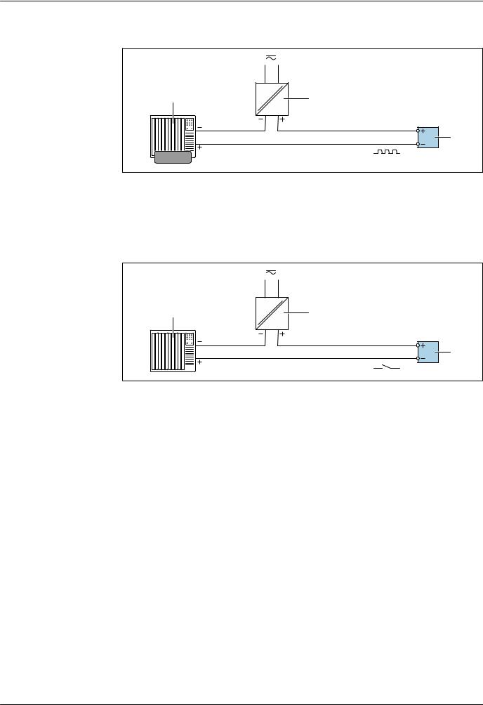
Proline Promag W 400
Pulse/frequency output
1 |
2 |
|
|
|
3 |
12345 |
|
|
A0028761 |
8 Connection example for pulse/frequency output (passive) 1 Automation system with pulse/frequency input (e.g. PLC)
2Power supply
3Transmitter: Observe input values → 13
Switch output
1 |
2 |
|
|
|
3 |
|
A0028760 |
9 Connection example for switch output (passive) 1 Automation system with switch input (e.g. PLC)
2Power supply
3 Transmitter: Observe input values → 13
26 |
Endress+Hauser |

Proline Promag W 400
PROFIBUS DP
1 |
2 |
3 |
|
A |
A |
|
4 |
|
|
|
|
|
B |
B |
|
|
|
|
|
A |
|
|
4 |
|
|
B |
|
|
A0028765 |
10 Connection example for PROFIBUS DP, non-hazardous area and Zone 2/Div. 2
1Control system (e.g. PLC)
2Cable shield: the cable shield must be grounded at both ends to comply with EMC requirements; observe cable specifications
3Transmitter
If baud rates > 1.5 MBaud an EMC cable entry must be used and the cable shield must continue as far as the terminal wherever possible.
Modbus RS485
1 |
2 |
3 |
|
A |
A |
|
4 |
|
|
|
|
|
B |
B |
|
|
|
|
|
A |
|
|
4 |
|
|
B |
|
|
A0028765 |
11 Connection example for Modbus RS485, non-hazardous area and Zone 2/Div. 2
1Control system (e.g. PLC)
2Cable shield: the cable shield must be grounded at both ends to comply with EMC requirements; observe cable specifications
3 Distribution box
4Transmitter
Endress+Hauser |
27 |

Proline Promag W 400
EtherNet/IP |
|
|
|
1 |
2 |
3 |
4 |
|
|
|
5 |
|
|
|
5 |
|
|
|
A0028767 |
12 Connection example for EtherNet/IP 1 Control system (e.g. PLC)
2Ethernet switch
3 Observe cable specifications
4 Device plug
5Transmitter
Status input
1 |
2 |
|
|
|
3 |
|
A0028764 |
13 Connection example for status input
1 Automation system with status output (e.g. PLC)
2Power supply
3Transmitter: Observe input values
Potential equalization |
Requirements |
Please consider the following to ensure correct measurement:
•Same electrical potential for the medium and sensor
•Remote version: same electrical potential for the sensor and transmitter
•Company-internal grounding concepts
•Pipe material and grounding
Connection example, standard scenario
Metal, grounded pipe
A0016315
14 Potential equalization via measuring tube
28 |
Endress+Hauser |

Proline Promag W 400
Connection example in special situations
Unlined and ungrounded metal pipe
This connection method also applies in situations where:
•The customary potential equalization is not used
•Equalizing currents are present
Ground cable |
Copper wire, at least 6 mm2 (0.0093 in2) |
|||||||||||||||
|
|
|
|
|
|
|
|
|
|
|
|
|
|
|
|
|
|
|
|
|
|
|
|
|
|
|
|
|
|
|
|
|
|
|
|
|
|
|
|
|
|
|
|
|
|
|
|
|
|
|
|
|
|
|
|
|
|
|
|
|
|
|
|
|
|
|
|
|
|
|
|
|
|
|
|
|
|
|
|
|
|
|
|
|
DN ≤ 300 |
DN ≥ 350 |
A0029338
15 Potential equalization via ground terminal and pipe flanges
Note the following when installing:
•Connect both sensor flanges to the pipe flange via a ground cable and ground them.
•Connect the connection housing of the transmitter or sensor to ground potential by means of the ground terminal provided for the purpose. To mount the ground cable:
–If DN ≤ 300 (12"): Mount the ground cable directly on the conductive flange coating of the sensor with the flange screws.
–If DN ≥ 350 (14"): Mount the ground cable directly on the metal transport bracket.
For remote device versions, the ground terminal in the example always refers to the sensor and not to the transmitter.
 You can order the necessary ground cable from Endress+Hauser: → 126.
Plastic pipe or pipe with insulating liner
This connection method also applies in situations where:
•The customary potential equalization is not used
•Equalizing currents are present
Ground cable |
Copper wire, at least 6 mm2 (0.0093 in2) |
|||||||||||||
|
|
|
|
|
|
|
|
|
|
|
|
|
|
|
|
|
|
|
|
|
|
|
|
|
|
|
|
|
|
|
|
|
|
|
|
|
|
|
|
|
|
|
|
|
|
|
|
|
|
|
|
|
|
|
|
|
|
|
|
|
|
|
|
|
|
|
|
|
|
|
|
|
|
|
|
|
|
|
|
|
|
|
|
|
|
|
|
|
|
A0029339
16 Potential equalization via ground terminal and ground disks
Note the following when installing:
The ground disks must be connected to the ground terminal via the ground cable and be connected to ground potential.
For remote device versions, the ground terminal in the example always refers to the sensor and not to the transmitter.
 The ground cable and ground disks can be ordered from Endress+Hauser → 126.
Endress+Hauser |
29 |

Proline Promag W 400
Pipe with a cathodic protection unit
This connection method is only used if the following two conditions are met:
•Metal pipe without liner or pipe with electrically conductive liner
•Cathodic protection is integrated in the personal protection equipment
Ground cable |
Copper wire, at least 6 mm2 (0.0093 in2) |
3
2 |
+ |
– |
1
A0030377
1 Connection of the two flanges of the pipe via a ground cable 2 Signal line shielding via a capacitor
3 Measuring device connected to power supply such that it is floating in relation to the protective ground (isolation transformer)
|
Note the following when installing: |
|
The sensor is installed in the pipe in a way that provides electrical insulation. |
|
For remote device versions, the ground terminal in the example always refers to the sensor and |
|
not to the transmitter. |
|
You can order the necessary ground cable from Endress+Hauser: → 126. |
|
|
terminals |
Transmitter |
|
• Supply voltage cable: plug-in spring terminals for wire cross-sections |
|
0.5 to 2.5 mm2 (20 to 14 AWG) |
|
• Signal cable: plug-in spring terminals for wire cross-sections 0.5 to 2.5 mm2 (20 to 14 AWG) |
|
• Electrode cable: spring terminals for wire cross-sections 0.5 to 2.5 mm2 (20 to 14 AWG) |
|
• Coil current cable: spring terminals for wire cross-sections 0.5 to 2.5 mm2 (20 to 14 AWG) |
|
Sensor connection housing |
|
Spring terminals for wire cross-sections0.5 to 2.5 mm2 (20 to 14 AWG) |
|
|
Cable entries |
Cable entry thread |
|
• M20 x 1.5 |
|
• Via adapter: |
|
– NPT ½" |
|
– G ½" |
Cable gland
•For standard cable: M20 × 1.5 with cable 6 to 12 mm (0.24 to 0.47 in)
•For reinforced cable: M20 × 1.5 with cable 9.5 to 16 mm (0.37 to 0.63 in)
 If metal cable entries are used, use a grounding plate.
Cable specification |
Permitted temperature range |
|
• The installation guidelines that apply in the country of installation must be observed. |
|
• The cables must be suitable for the minimum and maximum temperatures to be expected. |
|
Power supply cable |
|
Standard installation cable is sufficient. |
|
Signal cable |
|
Current output 0/4 to 20 mA |
|
Standard installation cable is sufficient. |
30 |
Endress+Hauser |
Loading...