


|
|
|
|
RTX 1000, RTX 2000 |
4 |
|
|
|
|
|
|
|
|
|
|
DAF Super Space Cap |
|
|
|
|
|
|
|
|
|
|
|
|
|
 1
1
q |
w |
e |
r |
t |
y |
u |
i |
o |
a |
s |
d |
≤ 4 m
 5
5
6 q j w  5 mm
5 mm
f |
g |
h |
j |
2 |
|
|
|
315 |
|
330 |
|
|
|
≥100 |
|
|
|
175 |
7 |
|
|
|
|
≥ 100 |
860 |
|
≥ 100 |
|
|
|
|
3 |
|
|
8 |
|
|
|
10 Nm
Nm
6 


 7
7 


8 Nm
7 |
6 |
|
A B
f
7
1

9 |
a |
A
C
M8 |
e |
|
|
r |
|
8,5 x 20 |
t |
|
M8 |
y |
|
M8 x 95 |
u |
5 Nm |
B
≥ 40
0
2.
1
g |
h |
i |
10 x 48 |
o |
10 x 40 |
a |
s |
M6 |
d |
M6 x 100
 b
b
 c
c
 24 V
24 V
1. |
g |
|
|
|
|
|
|
|
|
7.5 |
|
|
|
|
|
|
|
|
|
7.5 |
0 |
10 |
|
|
|
|
|
|
|
|
2 |
|
|
|
|
|
|
|
|
10 |
|
|
|
|
|
|
|
|
|
10 |
0 |
0 |
|
|
|
|
|
|
|
|
||
|
|
|
|
|
|
|
20 |
1 |
1 |
|
|
|
|
|
|
|
|
|
|
|
|
|
|
|
|
|
10 |
|
|
|
|
|
|
|
|
|
10 |
|
|
|
|
|
|
|
|
10 |
|
|
|
|
|
|
|
|
|
15 |
15 |
2 |
|
|
|
|
|
|
|
20 |
|
0 |
|
15 |
|
|
|
|
|
|
|
|
|
0 |
. |
|
. |
0 |
|
|
|
|
|
|
5 |
20 |
5 |
|
20 |
|
|
|
|
|
2 |
7 |
7 |
1 |
0 |
|
|
||
|
|
|
|
|
|
10 |
10 |
|
|
|
|
|
|
|
|
2 |
|
||
|
|
|
|
|
|
20 |
|
|
|
|
|
10 |
2 |
1 |
15 |
|
|
|
|
5 |
5 |
|
0 |
0 |
|
|
|
|
|
10 |
5 |
15 |
5 |
10 |
2 |
|
|
|
|
7 |
7 |
|
|
|
|
||||
|
. |
|
. |
|
0 |
|
|
|
|
Dometic WAECO International GmbH
Hollefeldstrasse 63
D-48282 Emsdetten
dometic.com
2
4445102183 L 11/2017
AIR CONDITIONERS
COOLAIR
RTX1000, RTX2000
Assembly kit for DAF XF 105/ EN 106 Super Space Cab
Installation Manual . . . . . . . . . . . . . . . . . . 3
Montagesatz für DAF XF 105/ DE 106 Super Space Cab
Montageanleitung . . . . . . . . . . . . . . . . . .14
Kit de montage pour DAF XF 105/ FR 106 Super Space Cab
Instructions de montage. . . . . . . . . . . . . 27
Juego de montaje para DAF XF 105/ ES 106 Super Space Cab
Instrucciones de montaje . . . . . . . . . . . . 39
Kit de montagem para DAF XF 105/ PT 106 Super Space Cab
Instruções de montagem . . . . . . . . . . . . 50
Set di montaggio per DAF XF 105/ IT 106 Super Space Cab
Indicazioni di montaggio . . . . . . . . . . . . 62
Montageset voor DAF XF 105/ NL 106 Super Space Cab
Montagehandleiding . . . . . . . . . . . . . . . 74
DA
SV
NO
FI
RU
PL
SK
CS
HU
Monteringssæt til DAF XF 105/ 106 Super Space Cab
Monteringsvejledning . . . . . . . . . . . . . . . 86
Monteringssats för DAF XF 105/ 106 Super Space Cab
Monteringsanvisning . . . . . . . . . . . . . . . . 98
Monteringssett for DAF XF 105/ 106 Super Space Cab
Monteringsanvisning . . . . . . . . . . . . . . . 110
Asennussarja malleihin DAF XF 105/ 106 Super Space Cab
Asennusohje . . . . . . . . . . . . . . . . . . . . . . 121
Монтажный комплект для DAF XF 105/ 106 Super Space Cab
Инструкция по монтажу . . . . . . . . . . . . 133
Zestaw montażowy do DAF XF 105/ 106 Super Space Cab
Instrukcja montażu . . . . . . . . . . . . . . . . . 145
Montážna súprava pre DAF XF 105/ 106 Super Space Cab
Návod na montáž . . . . . . . . . . . . . . . . . . 157
Montážní sada pro vozidla DAF XF 105/ 106 Super Space Cab
Návod k montáži. . . . . . . . . . . . . . . . . . . 169
Szerelőkészlet a következőkhöz: DAF XF 105/106 Super Space Cab
Szerelési útmutató . . . . . . . . . . . . . . . . . 180

CoolAir RTX1000, RTX2000
Original instructions
Please read this instruction manual carefully before installation and first use, and store it in a safe place. If you pass on the product to another person, hand over this instruction manual along with it.
Contents
1 Explanation of symbols . . . . . . . . . . . . . . . . . . . . . . . . . . . . . . . . . . 4
2 Safety instructions . . . . . . . . . . . . . . . . . . . . . . . . . . . . . . . . . . . . . . 4
2.1 Using the device. . . . . . . . . . . . . . . . . . . . . . . . . . . . . . . . . . . . . . . . . . . . . . . . . . . 4 2.2 Handling electrical cables . . . . . . . . . . . . . . . . . . . . . . . . . . . . . . . . . . . . . . . . . . . 5
3 Target group . . . . . . . . . . . . . . . . . . . . . . . . . . . . . . . . . . . . . . . . . . . 5 4 Intended use . . . . . . . . . . . . . . . . . . . . . . . . . . . . . . . . . . . . . . . . . . . 5 5 Scope of delivery . . . . . . . . . . . . . . . . . . . . . . . . . . . . . . . . . . . . . . . 6 6 Accessories . . . . . . . . . . . . . . . . . . . . . . . . . . . . . . . . . . . . . . . . . . . . 6 7 Installation. . . . . . . . . . . . . . . . . . . . . . . . . . . . . . . . . . . . . . . . . . . . . 7
7.1 Notes on installation. . . . . . . . . . . . . . . . . . . . . . . . . . . . . . . . . . . . . . . . . . . . . . . . 7 7.2 Removing the roof hatch . . . . . . . . . . . . . . . . . . . . . . . . . . . . . . . . . . . . . . . . . . . . 8 7.3 Preparing the unit . . . . . . . . . . . . . . . . . . . . . . . . . . . . . . . . . . . . . . . . . . . . . . . . . . 8 7.4 Attaching the seal for the cab roof. . . . . . . . . . . . . . . . . . . . . . . . . . . . . . . . . . . . . 9 7.5 Fitting the unit in the roof hatch . . . . . . . . . . . . . . . . . . . . . . . . . . . . . . . . . . . . . . . 9 7.6 Routing the electrical power supply leads . . . . . . . . . . . . . . . . . . . . . . . . . . . . . 10 7.7 Fixing the surround. . . . . . . . . . . . . . . . . . . . . . . . . . . . . . . . . . . . . . . . . . . . . . . . 10
8 Configuring the system software . . . . . . . . . . . . . . . . . . . . . . . . . .11
8.1 Entering and exiting configuration mode . . . . . . . . . . . . . . . . . . . . . . . . . . . . . . .11 8.2 P.01: Low voltage shut-down. . . . . . . . . . . . . . . . . . . . . . . . . . . . . . . . . . . . . . . . 12 8.3 P.02: Unit for temperature display. . . . . . . . . . . . . . . . . . . . . . . . . . . . . . . . . . . . 13
9 Technical data . . . . . . . . . . . . . . . . . . . . . . . . . . . . . . . . . . . . . . . . . 13
EN |
3 |
|
|
|
|

Explanation of symbols |
CoolAir RTX1000, RTX2000 |
1Explanation of symbols
!WARNING!
Safety instruction: Failure to observe this instruction can cause fatal or serious injury.
!CAUTION!
Safety instruction: Failure to observe this instruction can lead to injury.
ANOTICE!
Failure to observe this instruction can cause material damage and impair the function of the product.
INOTE
Supplementary information for operating the product.
2Safety instructions
The manufacturer accepts no liability for damage in the following cases:
•Faulty assembly or connection
•Damage to the product resulting from mechanical influences and excess voltage
•Alterations to the product without express permission from the manufacturer
•Use for purposes other than those described in the operating manual
2.1Using the device
•Only use the parking cooler for the purpose specified by the manufacturer and do not make any alterations or structural changes to the device.
•Do not use the parking cooler if it is visibly damaged.
•The parking cooler must be installed safely so that it cannot tip over or fall down.
•Installation, maintenance and repair work may only be carried out by qualified personnel from a specialist company who are familiar with the risks involved and the relevant regulations.
•Do not use the parking cooler near flammable fluids and gases.
•Do not operate the parking cooler if the ambient temperature is below 0 °C.
•Do not undo the upper cover of the parking cooler in the event of a fire. Use approved extinguishing agents instead. Do not use water to extinguish fires.
4 |
EN |
|

CoolAir RTX1000, RTX2000 |
Target group |
•Please inquire from your vehicle manufacturer whether the height entered in your vehicle documentation needs to be altered due to the installation of the parking cooler (height 175 mm).
•Disconnect all power supply lines when working on the parking cooler
(cleaning, maintenance, etc).
2.2Handling electrical cables
•Use cable ducts to lay cables through walls with sharp edges.
•Do not lay loose or bent cables next to electrically conductive materials (metal).
•Do not pull on the cables.
•Attach and lay the cables in such a manner that they cannot be tripped over or damaged.
•The electrical power supply may only be connected by a specialist workshop.
•The connection to the vehicle's electrical system should be protected by a
40 A fuse for the power supply and a 2 A fuse for the voltage monitor.
•Never lay power supply lines (battery leads) in the vicinity of signal or control cables.
3Target group
This installation manual contains the essential information and instructions for installing the parking cooler. It is intended for competent installer technical staff who are familiar with the guidelines and safety precautions to be applied when installing lorry accessories.
This installation manual should always be kept with the unit to which it relates.
4Intended use
This installation kit (item no. 9100300079) enables the installation of a CoolAir RTX1000 or RTX2000 parking cooler in a roof ventilation opening (hatch) provided at the plant in a DAF XF 105/106 Super Space Cab driver cab.
ANOTICE!
•The parking cooler is not suitable for installation in construction machines, agricultural machines or similar equipment. They will not work properly if exposed to strong vibrations.
•Operating parking cooler with voltages other than those specified can result in damage to the devices.
EN |
5 |
|
|
|
|

Scope of delivery |
CoolAir RTX1000, RTX2000 |
5Scope of delivery
CoolAir RTX1000, RTX2000 installation kit for DAF XF 105/106 Super Space Cab,
item no. 9100300079
Pos. in |
Part designation |
Quantity |
Ref. no. |
|
fig. 1 |
||||
|
|
|
||
|
|
|
|
|
|
Thread insert with flange M8 |
4 |
4445200068 |
|
|
|
|
|
|
|
Thread insert with flange M6 |
4 |
4445200069 |
|
|
|
|
|
|
|
Nut M8 |
4 |
4445200099 |
|
|
|
|
|
|
|
Fastening holder |
2 |
4442500618 |
|
|
|
|
|
|
|
Washer 8.5 x 20 |
4 |
4445200113 |
|
|
|
|
|
|
|
Spring washer M8 |
4 |
4445200091 |
|
|
|
|
|
|
|
Hex screw M8 x 95 |
4 |
4445200159 |
|
|
|
|
|
|
|
Spacer sleeve L = 48 mm, 10 mm |
4 |
4443900241 |
|
|
|
|
|
|
|
Spacer sleeve L = 40 mm, 10 mm |
4 |
4443900240 |
|
|
|
|
|
|
|
Cover frame DAF SSC |
1 |
4443000431 |
|
|
|
|
|
|
|
Washer M6 |
4 |
4445200115 |
|
|
|
|
|
|
|
Allen screw with cylindrical head M6 x 100 |
4 |
4445200092 |
|
|
|
|
|
|
|
2.5 m insulating tape (profile: 10 x 20 mm) |
1 |
4443300055 |
|
|
|
|
|
|
|
Connection cable 6 mm² x 4 m |
1 |
4441300250 |
|
|
|
|
|
|
|
Cable binder |
1 |
4445900256 |
|
|
|
|
|
|
|
1/4" hexagon bit |
1 |
4445900172 |
|
|
|
|
|
|
– |
Installation manual |
1 |
4445102183 |
|
|
|
|
|
6Accessories
Available as accessories (not included in the scope of delivery):
Part designation |
Ref. no. |
|
|
Connection cable 6 mm² x 11 m |
9100300108 |
|
|
Electrical fuse connection set RTX |
9100300110 |
|
|
6 |
EN |
|

CoolAir RTX1000, RTX2000 |
Installation |
7Installation
!CAUTION!
Incorrect installation of the parking cooler may place the safety of the user at risk.
The manufacturer accepts no liability whatsoever for personal injury or property damage if the parking cooler is not installed according to this installation manual.
ANOTICE!
•The parking cooler may only be installed by qualified personnel from a specialist company. The following information is intended for technicians who are familiar with the guidelines and safety precautions to be applied.
•The manufacturer only assumes liability for parts included in the scope of delivery. The validity of the warranty expires if the device is installed together with third-party parts.
•Check whether the roof of the vehicle is able to support the weight of a person before climbing onto it. Ask the vehicle manufacturer about the permitted roof loads.
7.1Notes on installation
The following tips and guidance should be followed when installing the parking cooler:
!WARNING! Electric shock hazard
Before carrying out any work on electrically operated components, make sure that they are disconnected from the power supply.
Before installing the parking cooler, disconnect all connections to the vehicle battery.
•Before installing the parking cooler, check whether any vehicle components could be damaged or have their function impaired as a result of the installa-
tion.
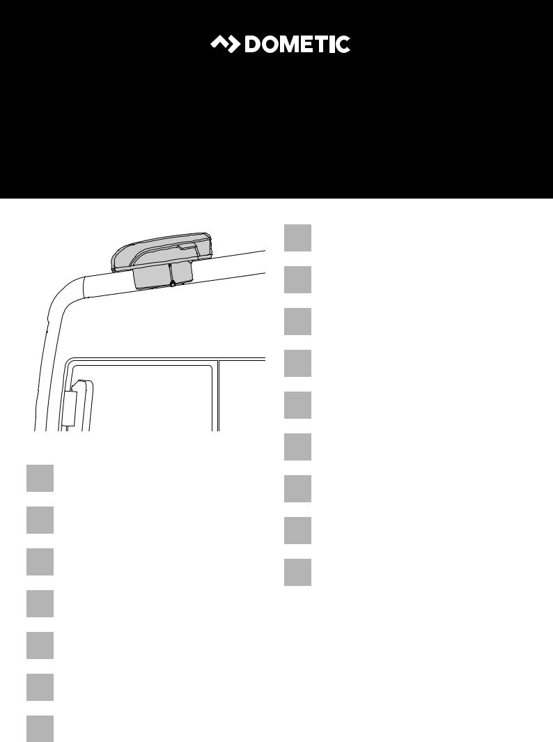
Check the dimensions of the system to be installed (fig. 2).
The dotted line indicates the middle of the roof hatch opening.
•The top cowl of the parking cooler can be painted (fig. 3). The manufacturer recommends that the painting is done by a specialist paint shop.
•Before installation, check with the vehicle manufacturer whether the vehicle body is designed for the static weight of the parking cooler and the dynamic loads created by it when the vehicle is in motion. The manufacturer of the parking cooler accepts no liability whatsoever in that regard.
EN |
7 |
|
|
|
|

Installation |
CoolAir RTX1000, RTX2000 |
•The downward slope of the roof in forward direction in the area where the unit is installed must not be more than:
–RTX1000: 8°
–RTX2000: 20°
•The assembly parts supplied must not be modified during installation.
•The ventilation openings must not be covered over (minimum distance from other external attachments: 100 mm).
•Follow the vehicle manufacturer's guidelines when installing the system and establishing the electrical connections.
INOTE
After installation of the system, the pre-set parameters on the system software must be checked (chapter “Configuring the system software” on page 11).
7.2Removing the roof hatch
Proceed as follows (fig. 5):
Remove all screws and fixings for the existing roof hatch.
Take out the roof hatch.
Remove the sealant around the opening so that the surface is clean and free of grease.
INOTE
Dispose of all waste material, glue, silicon and seals separately. When doing so, follow the waste disposal requirements applicable in your local area.
7.3Preparing the unit
ANOTICE!
When preparing the unit on the work surface, make sure it is secured against falling off.
Make sure that the work surface is clean and level to ensure that the unit is not damaged.
Proceed as follows (fig. 6):
Place the parking cooler on a work surface with the casing facing down.
Screw the 6 self-tapping M8 threaded plugs into the blind holes marked “6”.
To do so, use the 1/4" bit supplied.
Screw the 4 self-tapping M6 threaded plugs into the blind holes marked “7”. Use a 5 mm hexagon bit to do so.
8 |
EN |
|
CoolAir RTX1000, RTX2000 |
Installation |
7.4Attaching the seal for the cab roof
ANOTICE!
Ensure that the surface where the seal between the unit and the cab roof is to be glued is clean (free of dust, oil, etc.).
Glue the sealing strip to the cab roof (fig. 7 A).
Follow the contour of the roof hatch opening. The join between the ends of the seal should be at the back.
Apply a flexible, non-hardening butyl sealant (e.g. SikaLastomer-710) to the
join between the ends of the sealing strip and to the top edge of the sealing strip (fig. 7 B).
7.5Fitting the unit in the roof hatch
Place the parking cooler centrally and facing forwards in the roof hatch opening (fig. 8).
INOTE
Once the unit is in position on the vehicle roof, the seal should make contact all the way round. Only then can a reliable seal be achieved.
Position the fixing brackets underneath the cab roof (fig. 9).
When doing so, slide the fixing brackets between the cab roof (chassis) and the roof lining.
ANOTICE!
The fixing brackets must be positioned on a firm base since they will brace the unit against the cab roof. The contact area of the fixing brackets must be at least 40 mm on all sides.
ANOTICE!
Do not exceed the specified tightening torque under any circumstances. That is the only way to ensure that the threaded plugs are not pulled out.
Fix the parking cooler in place as illustrated (fig. 9).
EN |
9 |
|
|
|
|

Installation |
CoolAir RTX1000, RTX2000 |
7.6Routing the electrical power supply leads
!WARNING!
•The electrical connections may only be made by competent technical staff with the appropriate specialist knowledge.
•Before carrying out any work on electrically operated components, make sure that they are disconnected from the power supply.
ANOTICE!
•The connection to the vehicle's electrical system should be protected by a 40 A fuse for the power supply and a 2 A fuse for the voltage monitor.
•The battery must be capable of supplying the required current and voltage (chapter “Technical data” on page 13).
Connect the unit directly to the main power distribution box.
Ask your vehicle manufacturer for the specifications of the main power distribution box.
Route the power supply lead as illustrated (fig. 0):
Run the wiring loom to the main power distribution box along a route where it is protected.
Connect the negative lead (black) for the power supply.
Connect the negative lead (black) for the voltage monitor.
Connect the positive lead (red) for the power supply via a 40 A fuse.
Connect the positive lead (red) for the voltage monitor via a 2 A fuse.
Connect the wiring loom to the unit and fix with a cable tie in a suitable position (fig. 0 2.).
7.7Fixing the surround
ANOTICE!
Tighten the screws carefully in order not to damage the surround.
Fix the surround in place as illustrated (fig. a).
10 |
EN |
|

CoolAir RTX1000, RTX2000 |
Configuring the system software |
8Configuring the system software
Before the system is first put into operation, the control unit settings can be adjusted to suit the various installation conditions. Those adjustments must be made by the installer.
Display |
Parameter |
Meaning |
Factory |
|
indication |
setting |
|||
|
|
|||
|
|
|
|
|
P.01 |
Low voltage |
The battery monitor shuts down the |
22.8 V |
|
|
shut-down |
system at the voltage defined here. |
|
|
|
|
|
|
|
P.02 |
Unit for tempera- |
The temperature can be displayed in |
°C |
|
|
ture display |
°C or °F. |
|
|
|
|
|
|
INOTE
Configuration mode can still be activated if the low voltage cut-out has switched off the system and only residual voltage is available.
8.1Entering and exiting configuration mode
Press and hold the  button.
Press and hold the  button for longer than 3 s.
The display shows the symbol  .
.
The parking cooler switches to configuration mode.
The display shows “P.01” and the symbol flashes.
Scroll through the menu by pressing the or
or button to select the desired menu item.
Press the button to open the desired menu item.
Press and hold the  button for longer than 3 s to exit configuration mode.
EN |
11 |
|
|
|
|

Configuring the system software |
CoolAir RTX1000, RTX2000 |
8.2P.01: Low voltage shut-down
The battery monitor protects the battery against discharging excessively.
ANOTICE!
If the unit is switched off by the battery monitor, it means the battery charge level is low. Avoid repeated starting or using electrical equipment. Make sure that the battery is recharged. As soon as the required voltage is available again, the system can be operated again.
If only the power supply voltage specified here is available to the parking cooler, the system is switched off.
Switch to configuration mode (chapter “Entering and exiting configuration mode” on page 11).
The display shows “P.01” and the symbol  flashes.
Press the  button to change the setting.
The current setting is displayed.
Use the  or
or  button to select the voltage level for low voltage shutdown.
The low voltage shut-down setting can be adjusted in 0.1 V increments from
20.0 V to 23.5 V.
INOTE
The level for the low voltage shut-down should not be set any lower than the minimum battery voltage required to be able to start the engine under any conditions.
As a rule that should be no less than 22 V.
Press the  button to save the setting.
The set value is saved and is then applied when the system is restarted.
You are then returned to the menu and can select another menu item by pressing the  or
or  button.
12 |
EN |
|

CoolAir RTX1000, RTX2000 |
Technical data |
8.3P.02: Unit for temperature display
The system can display the room temperature in °C or °F. This parameter can be configured:
Switch to configuration mode (chapter “Entering and exiting configuration mode” on page 11).
The display shows “P.01” and the symbol  flashes.
Press the  or
or  button to select the menu item P.02.
The display shows “P.02” and the  symbol lights up.
Press the  button to change the setting.
The code for the current setting is displayed:
–0: °C
–1: °F
Use the  or
or  button to select the desired temperature unit.
Press the  button to save the setting.
The set value is saved and is then applied when the system is restarted.
You are then returned to the menu and can select another menu item by pressing the  or
or  button.
9Technical data
|
|
CoolAir |
|
|
RTX1000 |
|
RTX2000 |
|
|
||
|
|
|
|
Ref. number: |
|
|
|
24 V |
– |
|
9105306212 |
24 V 0° |
9105306210 |
|
– |
|
|
|
|
Cooling capacity: |
1200 W |
|
2000 W |
|
|
|
|
Rated input voltage: |
24 Vg (20 Vg – 30 Vg) |
||
|
|
|
|
Max. current consumption: |
5 – 25 A |
|
5 – 29 A |
|
|
|
|
Operating temperature range: |
+5 to +52 °C |
||
|
|
||
Low voltage shutdown: |
Configurable (chapter “P.01: Low voltage shut- |
||
|
down” on page 12) |
||
|
|
||
Noise emission: |
< 70 dB(A) |
||
|
|
||
Dimensions (L x B x H): |
645 x 860 x 308 mm |
||
|
|
|
|
Weight: |
approx. 23 kg |
|
approx. 32 kg |
|
|
|
|
EN |
13 |
|
|
|
|

CoolAir RTX1000, RTX2000
Original-Betriebsanleitung
Bitte lesen Sie diese Anleitung vor Einbau und Inbetriebnahme sorgfältig durch und bewahren Sie sie auf. Geben Sie sie im Falle einer Weitergabe des Produktes an den Nutzer weiter.
Inhaltsverzeichnis
1 |
Erklärung der Symbole. . . . . . . . . . . . . . . . . . . . . . . . . . . . . . . . . . |
15 |
2 |
Sicherheitshinweise . . . . . . . . . . . . . . . . . . . . . . . . . . . . . . . . . . . . |
15 |
2.1 |
Umgang mit dem Gerät. . . . . . . . . . . . . . . . . . . . . . . . . . . . . . . . . . . . . . . . . . . . |
.16 |
2.2 |
Umgang mit elektrischen Leitungen . . . . . . . . . . . . . . . . . . . . . . . . . . . . . . . . . . |
.16 |
3 |
Zielgruppe . . . . . . . . . . . . . . . . . . . . . . . . . . . . . . . . . . . . . . . . . . . . |
17 |
4 |
Bestimmungsgemäßer Gebrauch . . . . . . . . . . . . . . . . . . . . . . . . . |
17 |
5 |
Lieferumfang . . . . . . . . . . . . . . . . . . . . . . . . . . . . . . . . . . . . . . . . . . |
18 |
6 |
Zubehör . . . . . . . . . . . . . . . . . . . . . . . . . . . . . . . . . . . . . . . . . . . . . . |
18 |
7 |
Installation . . . . . . . . . . . . . . . . . . . . . . . . . . . . . . . . . . . . . . . . . . . . |
19 |
7.1 |
Hinweise zur Installation . . . . . . . . . . . . . . . . . . . . . . . . . . . . . . . . . . . . . . . . . . . |
.19 |
7.2 |
Dachluke ausbauen . . . . . . . . . . . . . . . . . . . . . . . . . . . . . . . . . . . . . . . . . . . . . . . |
20 |
7.3 |
Anlage vorbereiten . . . . . . . . . . . . . . . . . . . . . . . . . . . . . . . . . . . . . . . . . . . . . . . |
.21 |
7.4 |
Dichtung zum Fahrerhausdach anbringen . . . . . . . . . . . . . . . . . . . . . . . . . . . . . |
.21 |
7.5 |
Anlage in Dachluke einbauen . . . . . . . . . . . . . . . . . . . . . . . . . . . . . . . . . . . . . . . |
22 |
7.6 |
Elektrische Versorgungsleitungen verlegen. . . . . . . . . . . . . . . . . . . . . . . . . . . . |
23 |
7.7 |
Abdeckrahmen befestigen . . . . . . . . . . . . . . . . . . . . . . . . . . . . . . . . . . . . . . . . . |
23 |
8 |
Anlagen-Software konfigurieren . . . . . . . . . . . . . . . . . . . . . . . . . |
24 |
8.1 |
Einstellungsmodus starten und beenden . . . . . . . . . . . . . . . . . . . . . . . . . . . . . . |
24 |
8.2 |
P.01: Unterspannungsabschaltung. . . . . . . . . . . . . . . . . . . . . . . . . . . . . . . . . . . |
25 |
8.3 |
P.02: Anzeige Temperatureinheit. . . . . . . . . . . . . . . . . . . . . . . . . . . . . . . . . . . . |
26 |
9 |
Technische Daten . . . . . . . . . . . . . . . . . . . . . . . . . . . . . . . . . . . . . . |
26 |
14 |
DE |
|

CoolAir RTX1000, RTX2000 |
Erklärung der Symbole |
1Erklärung der Symbole
!WARNUNG!
Sicherheitshinweis: Nichtbeachtung kann zu Tod oder schwerer Verletzung führen.
!VORSICHT!
Sicherheitshinweis: Nichtbeachtung kann zu Verletzungen führen.
AACHTUNG!
Nichtbeachtung kann zu Materialschäden führen und die Funktion des Produktes beeinträchtigen.
IHINWEIS
Ergänzende Informationen zur Bedienung des Produktes.
2Sicherheitshinweise
Der Hersteller übernimmt in folgenden Fällen keine Haftung für Schäden:
•Montageoder Anschlussfehler
•Beschädigungen am Produkt durch mechanische Einflüsse und Überspannungen
•Veränderungen am Produkt ohne ausdrückliche Genehmigung vom
Hersteller
•Verwendung für andere als die in der Anleitung beschriebenen Zwecke
DE |
15 |
|
|
|
|

Sicherheitshinweise |
CoolAir RTX1000, RTX2000 |
2.1Umgang mit dem Gerät
•Benutzen Sie die Standklimaanlage nur für den vom Hersteller angegebenen Verwendungszweck und führen Sie keine Änderungen oder Umbauten am Gerät durch.
•Wenn die Standklimaanlage sichtbare Beschädigungen aufweist, darf Sie nicht in Betrieb genommen werden.
•Die Standklimaanlage muss so sicher installiert werden, dass diese nicht umstürzen oder herabfallen kann.
•Die Installation, Wartung und etwaige Reparatur dürfen nur durch einen Fachbetrieb erfolgen, der mit den damit verbundenen Gefahren bzw. einschlägigen Vorschriften vertraut ist.
•Setzen Sie die Standklimaanlage nicht in der Nähe von entflammbaren Flüssigkeiten und Gasen ein.
•Betreiben Sie die Standklimaanlage nicht bei Außentemperaturen unter 0 °C.
•Im Falle von Feuer lösen Sie nicht den oberen Deckel der Standklimaanlage, sondern verwenden Sie zugelassene Löschmittel. Verwenden Sie kein Wasser zum Löschen.
•Bitte informieren Sie sich bei Ihrem Fahrzeughersteller, ob aufgrund des
Aufbaues der Standklimaanlage (Aufbauhöhe 175 mm) eine Änderung des
Eintrags der Fahrzeughöhe in ihren Fahrzeugpapieren notwendig ist.
•Lösen Sie bei Arbeiten (Reinigung, Wartung usw.) an der Standklimaanlage alle Verbindungen zur Stromversorgung.
2.2Umgang mit elektrischen Leitungen
•Müssen Leitungen durch scharfkantige Wände geführt werden, so verwenden Sie Leerrohre bzw. Leitungsdurchführungen.
•Verlegen Sie keine losen oder scharf abgeknickten Leitungen an elektrisch leitenden Materialien (Metall).
•Ziehen Sie nicht an Leitungen.
•Befestigen und verlegen Sie Leitungen so, dass keine Stolpergefahr entsteht und eine Beschädigung des Kabels ausgeschlossen ist.
•Der elektrische Anschluss darf nur von einem Fachbetrieb durchgeführt werden.
•Sichern Sie den Anschluss ans Netz im Fahrzeug mit 40 A für die Stromversorgung und mit 2 A für die Spannungsmessung ab.
•Verlegen Sie niemals die Spannungsversorgungsleitung (Batteriekabel) in räumlicher Nähe zu Signaloder Steuerleitungen.
16 |
DE |
|

CoolAir RTX1000, RTX2000 |
Zielgruppe |
3Zielgruppe
Diese Montageanleitung enthält die wesentlichen Informationen und Anleitungen für die Installation der Standklimaanlage. Sie richtet sich an Facharbeiter in Installationsbetrieben, die mit den anzuwendenden Richtlinien und Sicherheitsvorkehrungen beim Einbau von Lkw-Zubehörteilen vertraut sind.
Diese Montageanleitung muss beim Gerät verbleiben.
4Bestimmungsgemäßer Gebrauch
Der Montagesatz (Art.-Nr. 9100300079) ermöglicht den Einbau einer Standklimaanlage CoolAir RTX1000 oder CoolAir RTX2000 in eine werkseitig vorhandene Dachlukenöffnung (Lüftungsluke) eines DAF XF 105/
106 Super Space Cab Fahrerhauses.
AACHTUNG!
•Die Standklimaanlage ist nicht für die Installation in Baumaschinen, Landmaschinen oder ähnlichen Arbeitsgeräten geeignet. Bei zu starker Vibrationseinwirkung ist eine ordnungsgemäße Funktion nicht gewährleistet.
•Der Betrieb der Standklimaanlage mit Spannungswerten, die von den angegebenen Werten abweichen, führt zur Beschädigung des Gerätes.
DE |
17 |
|
|
|
|

Lieferumfang |
CoolAir RTX1000, RTX2000 |
5Lieferumfang
CoolAir RTX1000, RTX2000 Montagesatz für
DAF XF 105/106 Super Space Cab,
Art.-Nr. 9100300079
Pos. in |
Teilebezeichnung |
Menge |
Art.-Nr. |
|
Abb. 1 |
||||
|
|
|
||
|
|
|
|
|
|
Gewindeeinsatz mit Flansch M8 |
4 |
4445200068 |
|
|
|
|
|
|
|
Gewindeeinsatz mit Flansch M6 |
4 |
4445200069 |
|
|
|
|
|
|
|
Mutter M8 |
4 |
4445200099 |
|
|
|
|
|
|
|
Befestigungshalter |
2 |
4442500618 |
|
|
|
|
|
|
|
Unterlegscheibe 8,5 x 20 |
4 |
4445200113 |
|
|
|
|
|
|
|
Federring M8 |
4 |
4445200091 |
|
|
|
|
|
|
|
Sechskantschraube M8 x 95 |
4 |
4445200159 |
|
|
|
|
|
|
|
Distanzhülse L = 48 mm, 10 mm |
4 |
4443900241 |
|
|
|
|
|
|
|
Distanzhülse L = 40 mm, 10 mm |
4 |
4443900240 |
|
|
|
|
|
|
|
Abdeckrahmen DAF SSC |
1 |
4443000431 |
|
|
|
|
|
|
|
Unterlegscheibe M6 |
4 |
4445200115 |
|
|
|
|
|
|
|
Schraube mit Zylinderkopf M6 x 100 |
4 |
4445200092 |
|
|
|
|
|
|
|
2,5 m Dichtungsband (Profil: 10 x 20 mm) |
1 |
4443300055 |
|
|
|
|
|
|
|
Anschlusskabel 6 mm² x 4 m |
1 |
4441300250 |
|
|
|
|
|
|
|
Kabelbinder |
1 |
4445900256 |
|
|
|
|
|
|
|
1/4"-Sechskant-Bit |
1 |
4445900172 |
|
|
|
|
|
|
– |
Montageanleitung |
1 |
4445102183 |
|
|
|
|
|
6 |
Zubehör |
|
|
Als Zubehör erhältlich (nicht im Lieferumfang enthalten): |
|
|
|
|
|
Teilebezeichnung |
Art.-Nr. |
|
|
|
|
Anschlusskabel 6 mm² x 11 m |
9100300108 |
|
|
|
|
Set Elektrische Absicherung RTX |
9100300110 |
|
|
|
18 |
DE |
|
CoolAir RTX1000, RTX2000 |
Installation |
7Installation
!VORSICHT!
Eine falsche Installation der Standklimaanlage kann die Sicherheit des Benutzers beeinträchtigen.
Wenn die Standklimaanlage nicht gemäß dieser Montageanleitung installiert wird, übernimmt der Hersteller keine Haftung für Personenoder Sachschäden.
AACHTUNG!
•Die Installation der Standklimaanlage darf ausschließlich von entsprechend ausgebildeten Fachbetrieben durchgeführt werden. Die nachfolgenden Informationen richten sich an Fachkräfte, die mit den anzuwendenden Richtlinien und Sicherheitsvorkehrungen vertraut sind.
•Der Hersteller übernimmt ausschließlich Haftung für im Lieferumfang enthaltene Teile. Beim Einbau der Anlage zusammen mit produktfremden Teilen entfallen die Gewährleistungsansprüche.
•Bevor Sie das Fahrzeugdach besteigen, prüfen Sie, ob dieses für Personen begehbar ist. Zulässige Dachlasten können Sie beim Fahrzeughersteller erfragen.
7.1Hinweise zur Installation
Folgende Tipps und Hinweise müssen bei der Installation der Standklimaanlage beachtet werden:
!WARNUNG! Stromschlaggefahr
Stellen Sie vor Arbeiten an elektrisch betriebenen Komponenten sicher, dass keine Spannung mehr anliegt.
Lösen Sie vor der Installation der Standklimaanlage alle Verbindungen zur
Fahrzeugbatterie.
•Prüfen Sie vor Installation der Standklimaanlage, ob durch den Einbau ggf.
Fahrzeugkomponenten beschädigt oder in ihrer Funktion beeinträchtigt
werden können.
Prüfen Sie die Abmessungen der eingebauten Anlage (Abb. 2).
Die gestrichelte Linie bezieht sich hierbei auf die Mitte der Dachlukenöffnung.
•Die Oberschale der Standklimaanlage darf lackiert werden (Abb. 3). Der Hersteller empfiehlt, die Lackierung von einer Fachwerkstatt vornehmen zu lassen.
•Klären Sie vor Einbau mit dem Fahrzeughersteller, ob der Aufbau für das statische Gewicht und die Belastungen durch die Klimaanlage bei in Bewegung befindlichem Fahrzeug ausgelegt ist. Der Hersteller der Standklimaanlage übernimmt keine Haftung.
DE |
19 |
|
|
|
|

Installation |
CoolAir RTX1000, RTX2000 |
•Die Dachneigung der Montagefläche darf in Fahrtrichtung nicht mehr betragen als:
–RTX1000: 8°
–RTX2000: 20°
•Die mitgelieferten Montageteile dürfen beim Einbau nicht eigenmächtig modifiziert werden.
•Die Lüftungsöffnungen dürfen nicht abgedeckt werden (Mindestabstand zu anderen Anbauteilen: 100 mm).
•Beachten Sie bei der Installation der Anlage und beim elektrischen Anschluss die Richtlinien des Fahrzeughersteller.
IHINWEIS
Nach der Installation der Anlage müssen die vorgegebenen Parameter der Anlagen-Software überprüft werden (Kapitel „Anlagen-Software konfigurieren“ auf Seite 24).
7.2Dachluke ausbauen
Gehen Sie wie folgt vor (Abb. 5):
Alle Schrauben und Befestigungen der vorhandenen Dachluke entfernen.
Dachluke heraus nehmen.
Dichtungsmaterial rund um die Öffnung entfernen, sodass der Untergrund sauber und fettfrei ist.
IHINWEIS
Entsorgen Sie sämtliches Abfallmaterial, Leim, Silikon und Dichtungen getrennt. Beachten Sie dabei die lokalen Entsorgungsrichtlinien.
20 |
DE |
|

CoolAir RTX1000, RTX2000 |
Installation |
7.3Anlage vorbereiten
AACHTUNG!
Sichern Sie die Anlage bei den Vorbereitungen auf der Arbeitsfläche gegen Herunterfallen.
Achten Sie auf eine ebene und saubere Unterlage, damit die Anlage nicht beschädigt wird.
Gehen Sie wie folgt vor (Abb. 6):
Standklimaanlage mit dem Gehäuse nach unten auf eine Arbeitsfläche legen.
Die 4 selbstschneidenden Gewindeeinsätze M8 in die mit „6“ gekennzeichneten Sacklöcher drehen.
Verwenden Sie hierzu den mitgelieferten 1/4"-Bit.
Die 4 selbstschneidenden Gewindeeinsätze M6 in die mit „7“ gekennzeichneten Sacklöcher drehen.
Verwenden Sie hierzu einen 5-mm-Sechskant-Bit.
7.4Dichtung zum Fahrerhausdach anbringen
AACHTUNG!
Stellen Sie sicher, dass die Klebefläche für die Dichtung zwischen Anlage und Fahrerhausdach sauber (frei von Staub, Öl usw.) ist.
Dichtungsband auf das Dach des Fahrerhauses kleben (Abb. 7 A).
Folgen Sie der Kontur der Dachlukenöffnung. Die Stoßkante muss hinten liegen.
Stoßkante und die Oberkante des Dichtungsbands mit einem plastischen
nicht aushärtenden Butyldichtstoff (z. B. SikaLastomer-710) versehen
(Abb. 7 B).
DE |
21 |
|
|
|
|

Installation |
CoolAir RTX1000, RTX2000 |
7.5Anlage in Dachluke einbauen
Standklimaanlage zentrisch und in Fahrtrichtung in die Dachlukenöffnung setzen (Abb. 8).
IHINWEIS
Nach dem Aufsetzen auf das Fahrzeugdach muss die Dichtung umlaufend anliegen. Nur so ist eine sichere Abdichtung möglich.
Befestigungshalter unter dem Fahrerhausdach (Abb. 9) positionieren. Die Befestigungshalter werden hierbei zwischen das Fahrerhausdach (Chassis) und den Dachhimmel geschoben.
AACHTUNG!
Die Befestigungshalter müssen auf einen festen Untergrund positioniert werden, da die Anlage durch die Halter gegen das Fahrerhausdach gegedrückt wird. Die Auflagefläche der Befestigungshalter muss an jeder Seite mindestens 40 mm betragen.
AACHTUNG!
Überschreiten Sie keinesfalls das angegebene Drehmoment. Nur so können Sie ein Ausreißen der Gewindeeinsätze vermeiden.
Standklimaanlage wie dargestellt befestigen (Abb. 9).
22 |
DE |
|

CoolAir RTX1000, RTX2000 |
Installation |
7.6Elektrische Versorgungsleitungen verlegen
!WARNUNG!
•Der elektrische Anschluss darf nur von Fachpersonal mit entsprechenden Kenntnissen durchgeführt werden.
•Vor Arbeiten an elektrisch betriebenen Komponenten ist sicherzustellen, dass keine Spannung anliegt.
AACHTUNG!
•Sichern Sie den Anschluss ans Netz im Fahrzeug mit 40 A für die Stromversorgung und mit 2 A für die Spannungsmessung ab.
•Die Batterie muss in der Lage sein, den benötigten Strom und die Spannung (Kapitel „Technische Daten“ auf Seite 26) zu liefern.
Schließen Sie die Anlage direkt am Hauptverteiler an.
Fragen Sie zu den Spezifikationen des Hauptverteilers Ihren Fahrzeughersteller.
Versorgungsleitung wie dargestellt verlegen (Abb. 0):
Kabelstrang an geschützter Stelle zum Hauptverteiler verlegen.
Minuskabel (schwarz) für die Stromversorgung anschließen.
Minuskabel (schwarz) für die Spannungsmessung anschließen.
Pluskabel (rot) für die Stromversorgung anschließen und mit 40 A absichern.
Pluskabel (rot) für die Spannungsmessung anschließen und mit 2 A absichern.
Kabelstrang mit der Anlage verbinden und an geeigneter Stelle mit einem Kabelbinder fixieren (Abb. 0 2.).
7.7Abdeckrahmen befestigen
AACHTUNG!
Ziehen Sie die Schrauben nur vorsichtig an, damit der Abdeckrahmen nicht beschädigt wird.
Abdeckrahmen wie dargestellt befestigen (Abb. a).
DE |
23 |
|
|
|
|

Anlagen-Software konfigurieren |
CoolAir RTX1000, RTX2000 |
8Anlagen-Software konfigurieren
Vor der ersten Inbetriebnahme der Anlage kann die Steuerung auf die unterschiedlichen Einbaugegebenheiten angepasst werden. Diese Anpassung muss von dem Einbauer vorgenommen werden.
Display- |
Parameter |
Bedeutung |
Werks- |
anzeige |
|
|
einstellung |
P.01 |
Unterspannungs- |
Der Batteriewächter schaltet bei der |
22,8 V |
|
abschaltung |
hier definierten Spannung die |
|
|
|
Anlage ab. |
|
|
|
|
|
P.02 |
Anzeige |
Die Temperatur kann in °C oder °F |
°C |
|
Temperatureinheit |
angezeigt werden. |
|
|
|
|
|
IHINWEIS
Der Einstellungsmodus kann auch noch aufgerufen werden, wenn der Unterspannungsschutz die Anlage ausgeschaltet hat und nur noch eine Restspannung zur Verfügung steht.
8.1Einstellungsmodus starten und beenden
Taste  drücken und gedrückt halten.
Taste  länger als 3 s drücken.
Das Display zeigt das Symbol  .
.
Die Standklimaanlage schaltet in den Einstellungsmodus.
Das Display zeigt „P.01“ an, und das Symbol leuchtet.
Mit den Tasten oder
oder durch die Menüliste scrollen, um das gewünschte Menü auszuwählen.
Taste drücken, um das gewünschte Menü zu öffnen.
Taste  länger als 3 s drücken, um den Einstellungsmodus zu verlassen.
24 |
DE |
|

CoolAir RTX1000, RTX2000 |
Anlagen-Software konfigurieren |
8.2P.01: Unterspannungsabschaltung
Der Batteriewächter schützt die Batterie vor zu tiefer Entladung.
AACHTUNG!
Die Batterie besitzt beim Abschalten durch den Batteriewächter nur noch einen Teil ihrer Ladekapazität. Vermeiden Sie mehrmaliges Starten oder den Betrieb von Stromverbrauchern. Sorgen Sie dafür, dass die Batterie wieder aufgeladen wird. Sobald die benötigte Spannung wieder zur Verfügung steht, kann die Anlage wieder betrieben werden.
Steht der Standklimaanlage nur noch die hier eingestellte Versorgungsspannung zur Verfügung, wird die Anlage abgeschaltet.
Einstellungsmodus starten (Kapitel „Einstellungsmodus starten und beenden“ auf Seite 24).
Das Display zeigt „P.01“ an, und das Symbol  leuchtet.
Taste  drücken, um den Wert zu ändern.
Der aktuell eingestellte Wert wird angezeigt.
Mit den Tasten  oder
oder  den Wert für die Unterspannungsabschaltung auswählen.
Die Unterspannungsabschaltung kann in 0,1-V-Schritten von 20,0 V bis 23,5 V eingestellt werden.
IHINWEIS
Der Wert für die Unterspannungsabschaltung darf nur so tief eingestellt werden, dass genügend Spannung an der Batterie anliegt, um jeder Zeit den Motor starten zu können.
In der Regel sollte der Wert nicht weniger als 22 V betragen.
Taste  drücken, um den Wert zu speichern.
Der eingestellte Wert wird gespeichert und beim Neustart der Anlage verwendet.
Sie befinden sich nun wieder in der Menüliste und können mit den Tasten  oder
oder  ein Menü wählen.
DE |
25 |
|
|
|
|

Technische Daten |
CoolAir RTX1000, RTX2000 |
8.3P.02: Anzeige Temperatureinheit
Die Anlage kann die Raumtemperatur in °C oder °F anzeigen. Dieser Parameter kann konfiguriert werden:
Einstellungsmodus starten (Kapitel „Einstellungsmodus starten und beenden“ auf Seite 24).
Das Display zeigt „P.01“ an, und das Symbol  leuchtet.
Mit den Tasten  oder
oder  das Menü P.02 wählen.
Das Display zeigt „P.02“ an, und das Symbol  leuchtet.
Taste  drücken, um den Wert zu ändern.
Die Kennzahl des aktuell eingestellten Wertes wird angezeigt:
–0: °C
–1: °F
Mit den Tasten  oder
oder  die gewünschte Temperatureinheit auswählen.
Taste  drücken, um den Wert zu speichern.
Der eingestellte Wert wird gespeichert und beim Neustart der Anlage verwendet.
Sie befinden sich nun wieder in der Menüliste und können mit den Tasten oder
oder  ein Menü wählen.
9Technische Daten
|
|
CoolAir |
|
|
RTX1000 |
|
RTX2000 |
|
|
||
|
|
|
|
Art.-Nr.: |
|
|
|
24 V |
– |
|
9105306212 |
24 V 0° |
9105306210 |
|
– |
|
|
|
|
Max. Kühlleistung: |
1200 W |
|
2000 W |
|
|
|
|
Anschlussspannung: |
24 Vg (20 Vg – 30 Vg) |
||
|
|
|
|
Max. Stromverbrauch: |
5 – 25 A |
|
5 – 29 A |
|
|
|
|
Betriebstemperaturbereich: |
+5 bis +52 °C |
||
|
|
||
Unterspannungsabschaltung: |
konfigurierbar (Kapitel „P.01: Unterspannungs- |
||
|
abschaltung“ auf Seite 25) |
||
|
|
|
|
Schallemissionen: |
|
< 70 dB(A) |
|
|
|
||
Maße (L x B x H): |
645 x 860 x 308 mm |
||
|
|
|
|
Gewicht: |
ca. 23 kg |
|
ca. 32 kg |
|
|
|
|
26 |
DE |
|

CoolAir RTX1000, RTX2000
Notice originale
Veuillez lire attentivement cette notice avant le montage et la mise en service. Veuillez ensuite la conserver. En cas de passer le produit, veuillez le transmettre au nouvel acquéreur.
Sommaire
1 Explication des symboles . . . . . . . . . . . . . . . . . . . . . . . . . . . . . . . 28
2 Consignes de sécurité . . . . . . . . . . . . . . . . . . . . . . . . . . . . . . . . . . 28
2.1 Précautions d’usage. . . . . . . . . . . . . . . . . . . . . . . . . . . . . . . . . . . . . . . . . . . . . . . 28 2.2 Précautions concernant les lignes électriques . . . . . . . . . . . . . . . . . . . . . . . . . . 29
3 Groupe cible . . . . . . . . . . . . . . . . . . . . . . . . . . . . . . . . . . . . . . . . . . 29 4 Usage conforme . . . . . . . . . . . . . . . . . . . . . . . . . . . . . . . . . . . . . . . 30 5 Contenu de la livraison . . . . . . . . . . . . . . . . . . . . . . . . . . . . . . . . . 30 6 Accessoires . . . . . . . . . . . . . . . . . . . . . . . . . . . . . . . . . . . . . . . . . . . 31 7 Installation. . . . . . . . . . . . . . . . . . . . . . . . . . . . . . . . . . . . . . . . . . . . 31
7.1 Consignes de sécurité concernant l'installation . . . . . . . . . . . . . . . . . . . . . . . . . 31 7.2 Démontez le lanterneau . . . . . . . . . . . . . . . . . . . . . . . . . . . . . . . . . . . . . . . . . . . . 32 7.3 Préparer le climatiseur . . . . . . . . . . . . . . . . . . . . . . . . . . . . . . . . . . . . . . . . . . . . . 33 7.4 Mettre en place le joint au niveau du toit de la cabine du conducteur . . . . . . . 33 7.5 Montez le climatiseur dans le lanterneau . . . . . . . . . . . . . . . . . . . . . . . . . . . . . . 34 7.6 Pose des câbles d'alimentation électrique . . . . . . . . . . . . . . . . . . . . . . . . . . . . . 35 7.7 Fixez le cadre de recouvrement . . . . . . . . . . . . . . . . . . . . . . . . . . . . . . . . . . . . . 35
8 Configuration du logiciel . . . . . . . . . . . . . . . . . . . . . . . . . . . . . . . . 36
8.1 Démarrage et arrêt du mode de réglage . . . . . . . . . . . . . . . . . . . . . . . . . . . . . . 36 8.2 P.01 : Arrêt sous-tension. . . . . . . . . . . . . . . . . . . . . . . . . . . . . . . . . . . . . . . . . . . . 37 8.3 P.02 : Affichage de l'unité de température. . . . . . . . . . . . . . . . . . . . . . . . . . . . . 38
9 Caractéristiques techniques . . . . . . . . . . . . . . . . . . . . . . . . . . . . . 38
FR |
27 |
|
|
|
|

Explication des symboles |
CoolAir RTX1000, RTX2000 |
1Explication des symboles
!AVERTISSEMENT !
Consigne de sécurité : le non-respect de ces consignes peut entraîner la mort ou de graves blessures.
!ATTENTION !
Consigne de sécurité : le non-respect de ces consignes peut entraîner des blessures.
AAVIS !
Le non-respect de ces consignes peut entraîner des dommages matériels et des dysfonctionnements du produit.
IREMARQUE
Informations complémentaires sur l'utilisation du produit.
2Consignes de sécurité
Le fabricant décline toute responsabilité pour des dommages dans les cas suivants :
•des défauts de montage ou de raccordement
•des influences mécaniques et des surtensions ayant endommagé le matériel
•des modifications apportées au produit sans autorisation explicite de la part du fabricant
•une utilisation différente de celle décrite dans la notice
2.1Précautions d’usage
•N’utilisez le climatiseur auxiliaire que pour l’usage prévu par le fabricant et n’effectuez aucune modification ou transformation de l’appareil .
•Si le climatiseur auxiliaire présente des dommages visibles, il ne doit pas être mis en marche.
•Le climatiseur auxiliaire doit être installé de manière à ce qu’il ne puisse ni se renverser ni tomber .
•Seule une entreprise spécialisée, parfaitement familiarisée avec les dangers et règlements spécifiques à ces manipulations, est autorisée à effectuer l’installation, l’entretien et les réparations éventuelles.
•N’utilisez pas le climatiseur auxiliaire à proximité de liquides inflammables et de gaz.
28 |
FR |
|
 Loading...