


SPX 1200I
 1
1
q |
|
fg |
f |
w |
|
|
|
d |
s |
a |
 5
5
. |
|
2. |
4x |
596 |
|
||
4. |
Ø 6,5 |
|
|
|
|
|
|
|
Ø 6,5 |
|
|
20 |
|
Ø 6,5 |
Ø 60 |
|
|
|
165 |
Ø 6,5 |
|
|
|
30 |
3. |
|
o |
t |
r e |
|
i |
|||
y |
|
||
|
u |
|
6
1.
Ø 36
Ø 13
2.
30
 2
2
648
3.
 146,5
146,5
7
280
3
1 |
2 |
3 |
r |
1. |
e |
|
w |
q |
2.
2,10
4
8
d |
f |
|
A |
1. |
2.
B |
g a |
s |
1
9 |
c |
CLICK
t |
u |
24 V
i |
o |
0
1 |
2 |
3 |
4 |
a
3.
b
1. |
|
2. |
3. |
|
5. |
Dometic WAECO International GmbH |
|
Hollefeldstrasse 63 |
|
D-48282 Emsdetten |
dometic.com
4445102619 08/2018
2
AIR CONDITIONERS
COOLAIR
SPX1200I |
|
|
|
Rear panel evaporator unit |
|
EN |
|
|
|
Installation Manual . . . . . . . . . . . . . . . . . . |
3 |
|
Rückwandverdampfereinheit |
|
DE |
|
|
|
Montageanleitung . . . . . . . . . . . . . . . . . . |
16 |
|
Unité d'évaporateur pour paroi |
|
FR |
|
|
|
arrière |
|
|
Instructions de montage. . . . . . . . . . . . . |
30 |
|
Evaporador para la pared trasera |
|
ES |
|
|
|
Instrucciones de montaje . . . . . . . . . . . . |
44 |
|
Unidade de evaporação para a |
|
PT |
|
|
|
parede traseira |
|
|
Instruções de montagem . . . . . . . . . . . . |
58 |
|
Unità di evaporazione per parete |
|
IT |
|
|
|
posteriore |
|
|
Indicazioni di montaggio . . . . . . . . . . . . |
72 |
|
Achterwandverdampereenheid |
|
NL |
|
|
|
Montagehandleiding . . . . . . . . . . . . . . . |
86 |
DA
SV
NO
FI
RU
PL
SK
CS
HU
Bagvægsfordamperenhed
Monteringsvejledning . . . . . . . . . . . . . . 100
Bakväggsförångarenhet
Monteringsanvisning . . . . . . . . . . . . . . . 113
Fordamperenhet for bakvegg
Monteringsanvisning . . . . . . . . . . . . . . . 126
Takaseinähaihdutinyksikkö
Asennusohje . . . . . . . . . . . . . . . . . . . . . . 139
Блок испарителя на задней стенке
Инструкция по монтажу . . . . . . . . . . . . 152
Jednostka parownika tylnej ścianki
Instrukcja montażu . . . . . . . . . . . . . . . . . 167
Jednotka výparníka určená na zadnú stenu
Návod na montáž . . . . . . . . . . . . . . . . . . 181
Výparníková jednotka na zadní stěně
Návod k montáži. . . . . . . . . . . . . . . . . . . 194
Hátfalrögzítésű párologtató egység
Szerelési útmutató . . . . . . . . . . . . . . . . .207

CoolAir SPX1200I
Original instructions
Contents
1 Symbols and formats . . . . . . . . . . . . . . . . . . . . . . . . . . . . . . . . . . . . 4 2 Safety instructions . . . . . . . . . . . . . . . . . . . . . . . . . . . . . . . . . . . . . . 4
2.1 Using the device. . . . . . . . . . . . . . . . . . . . . . . . . . . . . . . . . . . . . . . . . . . . . . . . . . . 4 2.2 Handling electrical cables . . . . . . . . . . . . . . . . . . . . . . . . . . . . . . . . . . . . . . . . . . . 5
3 Conventions in this manual . . . . . . . . . . . . . . . . . . . . . . . . . . . . . . . 5
3.1 General information on the installation manual. . . . . . . . . . . . . . . . . . . . . . . . . . . 5 3.2 Target group. . . . . . . . . . . . . . . . . . . . . . . . . . . . . . . . . . . . . . . . . . . . . . . . . . . . . . 6
4 Proper use . . . . . . . . . . . . . . . . . . . . . . . . . . . . . . . . . . . . . . . . . . . . . 6 5 Scope of delivery . . . . . . . . . . . . . . . . . . . . . . . . . . . . . . . . . . . . . . . 7 6 Installation. . . . . . . . . . . . . . . . . . . . . . . . . . . . . . . . . . . . . . . . . . . . . 7
6.1 Prescribed installation method . . . . . . . . . . . . . . . . . . . . . . . . . . . . . . . . . . . . . . . 7 6.2 Notes on installation. . . . . . . . . . . . . . . . . . . . . . . . . . . . . . . . . . . . . . . . . . . . . . . . 8 6.3 Determining the installation position. . . . . . . . . . . . . . . . . . . . . . . . . . . . . . . . . . . 9 6.4 Installing the evaporator unit . . . . . . . . . . . . . . . . . . . . . . . . . . . . . . . . . . . . . . . . 10 6.5 Sealing and attaching the hood. . . . . . . . . . . . . . . . . . . . . . . . . . . . . . . . . . . . . . .11 6.6 Routing supply lines to condenser unit . . . . . . . . . . . . . . . . . . . . . . . . . . . . . . . . .11 6.7 Connecting condenser unit to evaporator unit. . . . . . . . . . . . . . . . . . . . . . . . . . .11 6.8 Installing the electrical connection lines . . . . . . . . . . . . . . . . . . . . . . . . . . . . . . . 12
7 Configuration of unit software . . . . . . . . . . . . . . . . . . . . . . . . . . . 12
7.1 Entering and exiting configuration mode . . . . . . . . . . . . . . . . . . . . . . . . . . . . . . 13 7.2 P.01: Low voltage shut-down. . . . . . . . . . . . . . . . . . . . . . . . . . . . . . . . . . . . . . . . 13 7.3 P.02: Unit for temperature display. . . . . . . . . . . . . . . . . . . . . . . . . . . . . . . . . . . . 14 7.4 P.05: Tilt sensor . . . . . . . . . . . . . . . . . . . . . . . . . . . . . . . . . . . . . . . . . . . . . . . . . . 15
8 Technical data . . . . . . . . . . . . . . . . . . . . . . . . . . . . . . . . . . . . . . . . . 15
EN |
3 |
|
|
|
|

Symbols and formats |
CoolAir SPX1200I |
1Symbols and formats
!WARNING!
Safety instruction: Failure to observe this instruction can cause death or serious injury.
!CAUTION!
Safety instruction: Failure to observe this instruction can lead to injury.
ANOTICE!
Failure to observe this instruction can cause material damage and impair the function of the product.
INOTE
Supplementary information for operating the product.
2Safety instructions
The manufacturer accepts no liability for damage in the following cases:
•Faulty assembly or connection
•Damage to the product resulting from mechanical influences and incorrect connection voltage
•Alterations to the product without express permission from the manufacturer
•Use for purposes other than those described in the operating manual
2.1Using the device
•The freedom of movement of semi-trailers (of the outer edges of the semitrailer when turning or jackknifing) and other vehicle attachments must not be restricted.
•Only use the parking cooler for the purpose specified by the manufacturer and do not make any alterations or structural changes to the device.
•Only operate the parking cooler if you are certain that the housing and the cables are not damaged.
•Installation, maintenance and repair work may only be carried out by qualified personnel from a specialist company who are familiar with the risks involved and the relevant regulations.
•Do not use the parking cooler near flammable fluids or in closed rooms.
•Do not reach into air grilles or ventilation nozzles or insert any foreign objects in the system.
4 |
EN |
|
CoolAir SPX1200I |
Conventions in this manual |
•Do not open the system in the event of a fire. Use approved extinguishing agents instead. Do not use water to extinguish fires.
•Switch off the parking cooler before using automatic washing equipment (automatic car washes etc.) to clean the vehicle.
•Disconnect all connections to the power supply when carrying out work on the device.
•The system must be switched off before you tilt the cab.
2.2Handling electrical cables
•The electrical cables might be laid over sharp edges. Use ducts or tubes to prevent damage.
•Do not lay loose or bent cables next to electrically conductive materials
(metal).
•Do not pull on the cables.
•Attach and lay the cables in such a manner that they cannot be tripped over or damaged.
•The electrical power supply may only be connected by a specialist workshop.
•Fit a fuse of 25 A to the connection to the vehicle's power supply.
•Never lay power supply lines (battery leads) in the vicinity of signal or control cables.
•Where neeeded, secure cables with cable binders.
3Conventions in this manual
3.1General information on the installation manual
This installation manual contains the essential information and instructions for installing the parking cooler. The information is intended to be read by the installation personnel of the parking cooler.
The following instructions are intended to help you use the installation manual properly:
•The installation manual is part of the scope of delivery and should be stored carefully.
•The installation manual provides you with important information on the installation of the device and can also be used as a reference material in the event of repairs.
EN |
5 |
|
|
|
|

Proper use |
CoolAir SPX1200I |
•The manufacturer assumes no liability for non-observance of this installation manual. Any claims are excluded in this case.
3.2Target group
The installation and configuration information in this manual is intended for qualified installation personnel who are familiar with the guidelines and safety precautions to be applied during the installation of lorry accessory parts.
4Proper use
The CoolAir SPX1200 parking cooler is designed for supplying the cab of a lorry with cooled and dehumidified air. It can be used while driving.
The CoolAir SPX1200I rear panel evaporator unit (ref. no. 9105305612) can only be operated in combination with a CoolAir SPX1200C condenser unit. Both components together form the CoolAir SPX1200 parking cooler.
ANOTICE!
•The CoolAir SPX1200 parking cooler is not suitable for installation in agricultural machines and construction machines or similar equipment. It does not work properly in the event of strong vibrations and exposure to dust.
•Operating the SPX1200 parking cooler with voltages other than those specified can result in damage to the device.
INOTE
The SPX1200 parking cooler is only designed for ambient temperatures of up to 52 °C.
6 |
EN |
|

CoolAir SPX1200I |
Scope of delivery |
5Scope of delivery
Item in |
Part designation |
Quantity |
|
fig. 1 |
|||
|
|
||
|
|
|
|
. |
Evaporator unit with connecting cable |
1 |
|
|
|
|
|
3 |
Insulating plate |
1 |
|
|
|
|
|
$ |
Edge protection Ø 13 mm |
1 |
|
|
|
|
|
/ |
Edge protection Ø 36 mm |
1 |
|
|
|
|
|
1 |
Clip |
4 |
|
|
|
|
|
4 |
Screw M6 x 10 mm |
4 |
|
|
|
|
|
2 |
Cover for clip |
4 |
|
|
|
|
|
( |
Hood for rear panel |
1 |
|
|
|
|
|
, |
Self-tapping screw 3.5 x 9.5 mm |
4 |
|
|
|
|
|
" |
Plastic spacer L = 25 mm |
4 |
|
|
|
|
|
0 |
Hexagon screw M6 x 40 |
4 |
|
|
|
|
|
# |
Plastic spacer L = 40 mm |
8 |
|
|
|
|
|
% |
Hexagon screw M6 x 110 |
4 |
|
|
|
|
|
& |
Washer M6 (d1 = 6.4 mm, d2 = 20 mm) |
8 |
|
|
|
|
|
– |
Remote control (incl. type CR2025 battery) |
1 |
|
|
|
|
|
– |
Evaporator unit installation template |
1 |
|
|
|
|
6Installation
ANOTICE!
•The parking cooler may only be installed by qualified personnel from a specialist company. The following information is intended for specialists who are familiar with the guidelines and safety precautions to be applied.
•The evaporator unit must be installed in an upright position (fig. 2).
6.1Prescribed installation method
The parking cooler consists of the following components (fig. 3):
•CoolAir SPX1200C condenser unit (2)
•CoolAir SPX1200I rear panel evaporator unit (1) with connecting line (3)
The condenser unit (2) is attached to the firm and straight rear panel of the cab or by means of a firm fastening frame. The evaporator unit (1) is fitted on the inside of the rear panel of the cab.
EN |
7 |
|
|
|
|

Installation |
CoolAir SPX1200I |
INOTE
The connection line (3) can only be installed after fitting the evaporator unit and the condenser unit.
6.2Notes on installation
!WARNING! Danger of electrocution!
•Detach all connections to battery before starting installation of parking cooler.
•Make sure that all electrical components are electrically discharged before carrying out work on them.
!CAUTION!
Improper installation of the air conditioning roof unit can result in irreparable damage to the device and put the safety of the user at risk.
The manufacturer will not be held liable for claims if the air conditioning roof unit is not installed according to this installation manual. That applies to malfunctions and the safety of the air conditioning roof unit, in particular to injuries and damage to property.
INOTE
•The manufacturer strongly recommends the use of a vehicle-specific fastening frame for an optimum installation procedure for the SPX1200C condenser unit on the rear panel of the cab.
•Following installation of the unit, the specified unit software parameters must then be checked (chapter “Configuration of unit software” on page 12).
You should always read this installation manual all the way through before installing the parking cooler.
You should always observe the following tips and information when installing the parking cooler:
•Please consult the manufacturer of your vehicle with regard to the following.
–is the cab's rear panel a suitable location for attaching the unit?
–is the body designed to bear the static weight and loads occasioned by the parking cooler in a moving vehicle?
•Check the dimensions of the unit (fig. 2).
•Always check before installation of the unit whether any vehicle components could be damaged, deformed or impaired in terms of their functionality as a result of the installation.
•Avoid any unnecessary and frequent mechanical stress to the supply line between the evaporator unit and the condenser unit. Damage can result in the loss of refrigerant and impair the performance of the unit.
8 |
EN |
|
CoolAir SPX1200I |
Installation |
•The supplied assembly parts must not be modified during installation.
•The ventilation slots (grill) may not be covered (minimum distance from other attachment parts: 10 cm).
•You can connect the unit to the battery via the lorry's terminal block or directly. The terminal block is to be preferred for the connection. On some vehicles, larger consumers connected to the terminal block are switched off after a short while if the power requirement is too high. Ask your vehicle manufacturer for the specifications of the terminal block.
•Observe the body manufacturer's guidelines with regard to installation of the unit and its electrical connection.
6.3Determining the installation position
The system's installation position must meet the following criteria:
•All maintenance work must be easy to perform.
•Sufficient space must be available for the refrigerant line.
•The refrigerant line must be long enough (approx. 2.1 m) for connection of
the condenser and evaporator unit. The line must not be routed under tension (fig. 3).
•The fastening surface should be as flat as possible. Use spacer sleeves for uneven surfaces. If spacer sleeves are used, appropriately longer fastening screws with sufficient tensile strength (not included in the assembly set) must then be used.
INOTE
The fastening screws M6 x 40 mm included are designed for use with the spacer sleeves, l = 25 mm, (e.g. MAN TGX).
The fastening screws M6 x 110 mm included are designed for use with the spacer sleeves, l = 40 mm, (e.g. Volvo FH as of construction year 2013) (two spacer sleeves for each screw).
By combining the spacer sleeves, different distances between the rear wall of the cab and inner trim can be achieved.
The screw overhang beyond the nut must not exceed 15 mm.
If spacer sleeves are not to be used or if other ones are to be used, the fastening screws have to then be adapted to match them. Otherwise the unit housing may be damaged.
EN |
9 |
|
|
|
|

Installation |
CoolAir SPX1200I |
6.4Installing the evaporator unit
The evaporator unit is fitted horizontally on the cab's rear panel, near the bunk.
Find a suitable fastening position in the cab that allows sufficient air circulation.
ANOTICE!
•Make sure that the drill template included is not upside down when positioned.
•You can position the drill template from the inside or from the outside onto the cab. Make sure that the following holes are used for the connecting and condensation line:
–from inside: holes that bear the inscription “Inside”
–from outside: holes that bear the inscription “Outside”
Drill the holes for mounting the evaporator unit (fig. 5).
INOTE
If the space between the interior trim and the cab's rear panel is large, the hole (Ø 15 mm) for the inclined condensation line must be drilled slightly lower than specified on the template. For a distance for the interior trim to the cab's rear panel of approx. 25 mm the hole (Ø 15 mm) should be drilled approx. 5 mm lower to ensure that the condensation drainage process functions.
Drill the hole for the connection line (Ø 30 mm) (fig. 6).
Drill the hole for the condensation line (Ø 13 mm) (fig. 6).
ANOTICE!
Make sure that the coupling half with the thin, capillary tube is not twisted or kinked.
Carefully unwind the connection line.
Fit the evaporator unit (fig. 7).
Fasten the evaporator unit from the outside (fig. 8).
10 |
EN |
|

CoolAir SPX1200I |
Installation |
6.5Sealing and attaching the hood
ANOTICE!
When bending the supply line make sure that the radius is not too narrow. Use a suitable round object with a shim as a bending aid.
A radius which is too narrow will kink the refrigerant line, and this will prevent the parking cooler from operating.
INOTE
If you wish to avoid damaging the cab's rear panel (drilling a hole), you can also fix the hood in place using a suitable adhesive. Observe the instructions provided by the adhesive manufacturer.
Mount one clip (fig. 9).
Mount the hood (fig. 9).
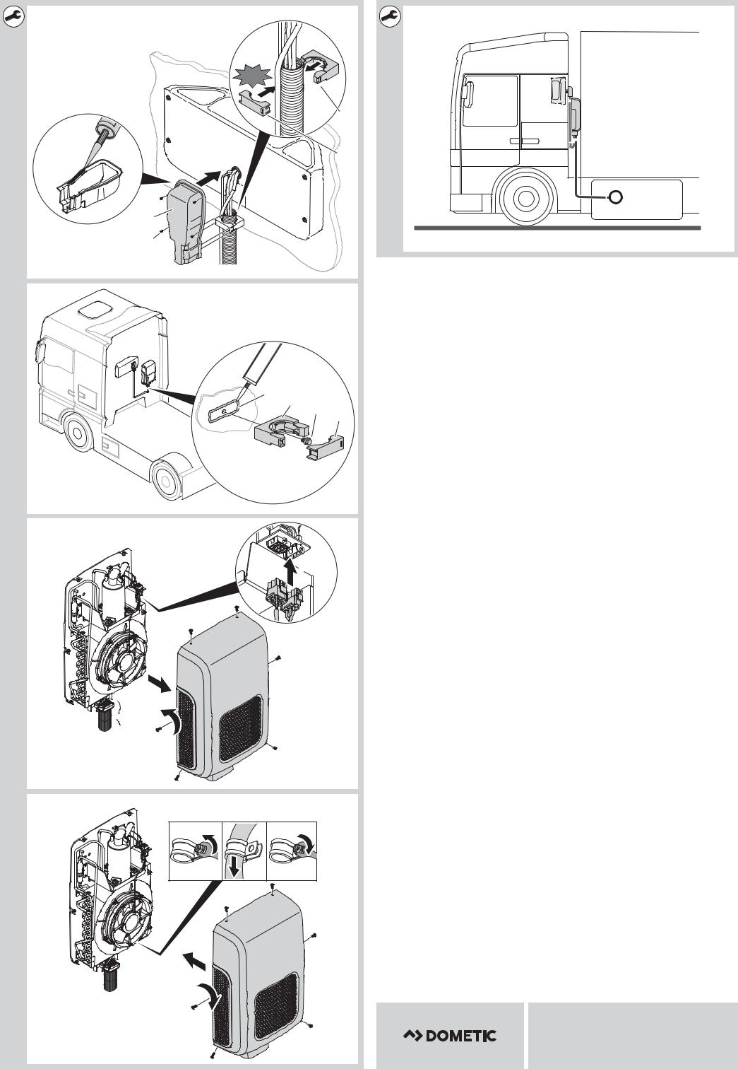
6.6Routing supply lines to condenser unit
INOTE
•The installation manual for the SPX1200C condenser unit should also be observed.
•Mount the SPX1200C condenser unit first to enable the exact position of the condenser unit to be determined. This will save you bending the copper pipe several times to make it fit.
•Make sure that the maximum length of the supply lines does not exceed
2.1 m.
•Avoid any narrow radiuses when routing and bending supply lines. Use a suitable round object with a shim as a bending aid. A radius which is too narrow will kink the refrigerant line, and this will prevent the parking cooler from operating.
•If you wish to avoid damaging the cab's rear panel, you can also fix the clip in place using a suitable adhesive. Observe the instructions provided by the adhesive manufacturer.
Shorten any supply line which is not needed by bending a curve.
Fasten the supply lines to the cab's rear panel using the clips (fig. 0).
6.7Connecting condenser unit to evaporator unit
Route the connection cable in a curve out through the opening in the floor of the condenser unit.
Fasten the connection cable as shown (fig. a and fig. b).
EN |
11 |
|
|
|
|

Configuration of unit software |
CoolAir SPX1200I |
6.8Installing the electrical connection lines
!WARNING!
•The electrical power supply may only be performed by qualified personnel with specialist knowledge.
•Make sure there is no voltage present on electrically operated components before carrying out work on them.
ANOTICE!
•Fit a fuse of 25 A to the connection to the vehicle's power supply.
•The battery must be able to supply the required current and voltage (chapter “Technical data” on page 15).
INOTE
The unit is equipped as standard with a 4 m long cable with a cross-section of 8 mm2. If longer cable lengths are required, then the cable cross-section must be increased by an authorised specialist workshop:
In this case, extend the cable using a 16 mm² cable. Make a professional connection.
The 16 mm² cable must not be longer than 8 m.
You can connect the unit to the battery via the lorry's terminal block or directly.
The terminal block is to be preferred for the connection. Ask your vehicle manufacturer for the specifications of the terminal block.
Lay the connection line.
Connect it to the vehicle (fig. c).
7Configuration of unit software
Before the system is first put into operation, the control unit settings can be adjusted to suit the various installation conditions. Those adjustments must be made by the installer (fig. 4).
Display |
Parameter |
Meaning |
Factory |
|
indication |
setting |
|||
|
|
|||
|
|
|
|
|
P.01 |
Low voltage |
The battery monitor shuts down the |
22.8 V |
|
|
shut-down |
system at the voltage defined here. |
|
|
|
|
|
|
|
P.02 |
Unit for tempera- |
The temperature can be displayed in |
°C |
|
|
ture display |
°C or °F. |
|
|
|
|
|
|
|
P.05 |
Tilt sensor |
The tilt sensor can be adjusted to the |
– |
|
|
|
inclination of the vehicle roof. |
|
|
|
|
|
|
12 |
EN |
|

CoolAir SPX1200I |
Configuration of unit software |
INOTE
Configuration mode can still be activated if the low voltage cut-out has switched off the system and only residual voltage is available.
7.1Entering and exiting configuration mode
Press and hold the  button.
Press and hold the  button for longer than 3 s.
The display shows the symbol  .
.
The parking cooler switches to configuration mode.
The display shows “P.01” and the symbol flashes.
Scroll through the menu by pressing the or
or button to select the desired menu item.
Press the  button to open the desired menu item.
Press and hold the  button for longer than 3 s to exit configuration mode.
7.2P.01: Low voltage shut-down
The battery monitor protects the battery against discharging excessively.
ANOTICE!
If the unit is switched off by the battery monitor, it means the battery charge level is low. Avoid repeated starting or using electrical equipment. Make sure that the battery is recharged. As soon as the required voltage is available again, the system can be operated again.
If only the power supply voltage specified here is available to the parking cooler, the system is switched off.
Switch to configuration mode (chapter “Entering and exiting configuration mode” on page 13).
The display shows “P.01” and the symbol  flashes.
Press the  button to change the setting.
The current setting is displayed.
Use the  or
or  button to select the voltage level for low voltage shutdown.
The low voltage shut-down setting can be adjusted in 0.1 V increments from
20.0 V to 23.5 V.
EN |
13 |
|
|
|
|

Configuration of unit software |
CoolAir SPX1200I |
INOTE
The level for the low voltage shut-down should not be set any lower than the minimum battery voltage required to be able to start the engine under any conditions.
As a rule that should be no less than 22 V.
Press the  button to save the setting.
The set value is saved and is then applied when the system is restarted.
You are then returned to the menu and can select another menu item by pressing the  or
or  button.
7.3P.02: Unit for temperature display
The system can display the room temperature in °C or °F. This parameter can be configured:
Switch to configuration mode (chapter “Entering and exiting configuration mode” on page 13).
The display shows “P.01” and the symbol  flashes.
Press the  or
or  button to select the menu item P.02.
The display shows “P.02” and the  symbol lights up.
Press the  button to change the setting.
The code for the current setting is displayed:
–0: °C
–1: °F
Use the  or
or  button to select the desired temperature unit.
Press the  button to save the setting.
The set value is saved and is then applied when the system is restarted.
You are then returned to the menu and can select another menu item by pressing the  or
or  button.
14 |
EN |
|

CoolAir SPX1200I |
Technical data |
7.4P.05: Tilt sensor
The electronics of the system prevents that the system is switched on when the vehicle is parked at a slope. Since some vehicles‘ roof already is tilted, the tilt sensor has to calibrated to the zero setting before first use.
Park the vehicle on a level place.
Switch to configuration mode (chapter “Entering and exiting configuration mode” on page 13).
The display shows “P.01” and the symbol  flashes.
Press the  or
or  button to select the menu item P.05.
The display shows “P.05”.
Press the  button to change the setting.
The code for the current setting is displayed.
Use the  or
or  button to select “1”.
Press the  button to save the setting.
The set value is saved and is then applied when the system is restarted.
You are then returned to the menu and can select another menu item by pressing the  or
or  button.
8Technical data
|
CoolAir SPX1200 parking cooler |
||
|
with SPX1200I rear panel evaporator unit |
||
|
|
|
|
Cooling capacity: |
|
1200 W |
|
|
|
|
|
Rated input voltage: |
24 Vg |
||
|
|
|
|
Input voltage range: |
20 Vg – 30 Vg |
||
|
|
|
|
Operating temperature range: |
|
+5 to +52 °C |
|
|
|
|
|
Current consumption: |
12 – 22 A |
||
|
|
|
|
Low-voltage cut-off: |
Configurable |
||
|
|
|
|
Dimensions (W x H x D): |
Condenser unit 346 x 560 x 156 mm |
||
|
Evaporator unit 648 x 278 x 144 mm |
||
|
|
|
|
Weight: |
|
Evaporator unit 15 kg |
|
|
(including connection lines) |
||
|
Condenser unit 21 kg (without fastening frame) |
||
|
|
|
|
Inspection/certification: |
|
|
|
|
|
|
|
|
|
|
|
|
|
|
|
EN |
15 |
|
|
|
|

CoolAir SPX1200I
Original-Betriebsanleitung
Inhaltsverzeichnis
1 Erklärung der Symbole. . . . . . . . . . . . . . . . . . . . . . . . . . . . . . . . . . 17 2 Sicherheitshinweise . . . . . . . . . . . . . . . . . . . . . . . . . . . . . . . . . . . . 17
2.1 Umgang mit dem Gerät. . . . . . . . . . . . . . . . . . . . . . . . . . . . . . . . . . . . . . . . . . . . .17 2.2 Umgang mit elektrischen Leitungen . . . . . . . . . . . . . . . . . . . . . . . . . . . . . . . . . . .18
3 Handbuchkonventionen . . . . . . . . . . . . . . . . . . . . . . . . . . . . . . . . 19
3.1 Allgemeine Informationen zur Einbauanleitung. . . . . . . . . . . . . . . . . . . . . . . . . .19 3.2 Zielgruppe . . . . . . . . . . . . . . . . . . . . . . . . . . . . . . . . . . . . . . . . . . . . . . . . . . . . . . .19
4 Bestimmungsgemäße Anwendung . . . . . . . . . . . . . . . . . . . . . . . 19
5 Lieferumfang . . . . . . . . . . . . . . . . . . . . . . . . . . . . . . . . . . . . . . . . . . 20
6 Installation . . . . . . . . . . . . . . . . . . . . . . . . . . . . . . . . . . . . . . . . . . . . 21
6.1 Vorgeschriebene Installationsweise . . . . . . . . . . . . . . . . . . . . . . . . . . . . . . . . . . .21 6.2 Hinweise zur Installation . . . . . . . . . . . . . . . . . . . . . . . . . . . . . . . . . . . . . . . . . . . .21 6.3 Anbauposition bestimmen . . . . . . . . . . . . . . . . . . . . . . . . . . . . . . . . . . . . . . . . . 23 6.4 Verdampfereinheit einbauen . . . . . . . . . . . . . . . . . . . . . . . . . . . . . . . . . . . . . . . 23 6.5 Abdichtung und Anbringen der Abdeckhaube. . . . . . . . . . . . . . . . . . . . . . . . . 24 6.6 Versorgungsleitungen zur Kondensatoreinheit verlegen . . . . . . . . . . . . . . . . . 25 6.7 Kondensatoreinheit mit der Verdampfereinheit verbinden. . . . . . . . . . . . . . . . 25 6.8 Elektrische Anschlussleitungen verlegen . . . . . . . . . . . . . . . . . . . . . . . . . . . . . . 25
7 Konfiguration der Anlagen-Software . . . . . . . . . . . . . . . . . . . . . . 26
7.1 Einstellungsmodus starten und beenden . . . . . . . . . . . . . . . . . . . . . . . . . . . . . . 26 7.2 P.01: Unterspannungsabschaltung. . . . . . . . . . . . . . . . . . . . . . . . . . . . . . . . . . . 27 7.3 P.02: Anzeige Temperatureinheit. . . . . . . . . . . . . . . . . . . . . . . . . . . . . . . . . . . . 28 7.4 P.05: Neigungssensor. . . . . . . . . . . . . . . . . . . . . . . . . . . . . . . . . . . . . . . . . . . . . 28
8 Technische Daten . . . . . . . . . . . . . . . . . . . . . . . . . . . . . . . . . . . . . . 29
16 |
DE |
|

CoolAir SPX1200I |
Erklärung der Symbole |
1Erklärung der Symbole
!WARNUNG!
Sicherheitshinweis: Nichtbeachtung kann zu Tod oder schwerer Verletzung führen.
!VORSICHT!
Sicherheitshinweis: Nichtbeachtung kann zu Verletzungen führen.
AACHTUNG!
Nichtbeachtung kann zu Materialschäden führen und die Funktion des Produktes beeinträchtigen.
IHINWEIS
Ergänzende Informationen zur Bedienung des Produktes.
2Sicherheitshinweise
Der Hersteller übernimmt in folgenden Fällen keine Haftung für Schäden:
•Montageoder Anschlussfehler
•Beschädigungen am Produkt durch mechanische Einflüsse und falsche
Anschlussspannung
•Veränderungen am Produkt ohne ausdrückliche Genehmigung vom
Hersteller
•Verwendung für andere als die in der Anleitung beschriebenen Zwecke
2.1Umgang mit dem Gerät
•Die Bewegungsfreiheit von Aufliegern (die äußeren Kanten des Aufliegers beim Einlenken oder Einknicken) und anderen Fahrzeuganbauten darf nicht eingeschränkt werden.
•Benutzen Sie die Standklimaanlage nur für den vom Hersteller angegebenen Verwendungszweck und führen Sie keine Änderungen oder Umbauten am Gerät durch.
•Wenn die Standklimaanlage sichtbare Beschädigungen aufweist, darf Sie nicht in Betrieb genommen werden.
•Die Installation, Wartung und etwaige Reparatur dürfen nur durch einen Fachbetrieb erfolgen, der mit den damit verbundenen Gefahren bzw. einschlägigen Vorschriften vertraut ist.
DE |
17 |
|
|
|
|

Sicherheitshinweise |
CoolAir SPX1200I |
•Setzen Sie die Standklimaanlage nicht in der Nähe von entflammbaren Flüssigkeiten und Gasen oder in geschlossenen Räumen ein.
•Greifen Sie nicht in Lüftungsgitter oder Lüftungsdüsen, und stecken Sie keine Fremdgegenstände in die Anlage.
•Im Falle von Feuer öffnen Sie die Anlage nicht, sondern verwenden Sie zugelassene Löschmittel. Verwenden Sie kein Wasser zum Löschen.
•Schalten Sie die Standklimaanlage aus, bevor Sie automatische Wascheinrichtungen (automatische Waschanlage usw.) zum Reinigen des Fahrzeugs verwenden.
•Lösen Sie bei Arbeiten (Reinigung, Wartung usw.) an der Standklimaanlage alle Verbindungen zur Stromversorgung.
•Schalten Sie vor dem Umklappen des Fahrerhauses die Anlage aus.
2.2Umgang mit elektrischen Leitungen
•Müssen Leitungen durch scharfkantige Wände geführt werden, so verwenden Sie Leerrohre bzw. Leitungsdurchführungen.
•Verlegen Sie keine losen oder scharf abgeknickten Leitungen an elektrisch leitenden Materialien (Metall).
•Ziehen Sie nicht an Leitungen.
•Befestigen und verlegen Sie Leitungen so, dass keine Stolpergefahr entsteht und eine Beschädigung des Kabels ausgeschlossen ist.
•Der elektrische Anschluss darf nur von einem Fachbetrieb durchgeführt werden.
•Sichern Sie den Anschluss ans Netz im Fahrzeug mit 25 A ab.
•Verlegen Sie niemals die Spannungsversorgungsleitung (Batteriekabel) in räumlicher Nähe zu Signaloder Steuerleitungen.
•Sichern Sie die Kabel durch Kabelbinder wenn erforderlich.
18 |
DE |
|
CoolAir SPX1200I |
Handbuchkonventionen |
3Handbuchkonventionen
3.1Allgemeine Informationen zur Einbauanleitung
Diese Einbauanleitung enthält die wesentlichen Informationen und Anleitungen für die Installation der Standklimaanlage. Die enthaltenen Informationen richten sich an den Installationsbetrieb der Standklimaanlage.
Folgende Hinweise helfen Ihnen bei der korrekten Anwendung der Einbauanleitung:
•Die Einbauanleitung ist Teil des Lieferumfangs und ist sorgfältig aufzubewahren.
•Die Einbauanleitung gibt Ihnen wichtige Hinweise für die Montage und dient gleichzeitig in Reparaturfällen als Nachschlagewerk.
•Bei Nichtbeachtung dieser Einbauanleitung haftet der Hersteller nicht. Jegliche Ansprüche sind für diesen Fall ausgeschlossen.
3.2Zielgruppe
Installationsund Konfigurationsinformationen in dieser Anleitung richten sich an Facharbeiter in Installationsbetrieben, die mit den anzuwendenden Richtlinien und Sicherheitsvorkehrungen beim Einbau von Lkw-Zubehörteilen vertraut sind.
4Bestimmungsgemäße Anwendung
Die Standklimaanlage CoolAir SPX1200 dient dazu, das Fahrerhaus eines LKW mit gekühlter und entfeuchteter Luft zu klimatisieren. Der Einsatz während der
Fahrt ist möglich.
Die Rückwandverdampfereinheit CoolAir SPX1200I (Art.-Nr. 9105305612) ist nur in Verbindung mit einer Kondensatoreinheit CoolAir SPX1200C funktionsfähig. Beide Komponenten zusammen bilden die Standklimaanlage CoolAir
SPX1200.
AACHTUNG!
•Die Standklimaanlage SPX1200 ist nicht für die Installation in Landund Baumaschinen oder ähnlichen Arbeitsgeräten geeignet. Bei zu starker Vibrationsund Staubeinwirkung ist eine ordnungsgemäße Funktion
nicht gewährleistet.
•Der Betrieb der Standklimaanlage SPX1200 mit Spannungswerten, die von den angegebenen Werten abweichen, führt zur Beschädigung des Gerätes.
DE |
19 |
|
|
|
|

Lieferumfang |
CoolAir SPX1200I |
IHINWEIS
Die Standklimaanlage SPX1200 ist für eine Umgebungstemperatur nicht über 52 °C im Kühlbetrieb ausgelegt.
5Lieferumfang
Pos. in |
Teilebezeichnung |
Menge |
Abb. 1 |
||
|
|
|
. |
Verdampfereinheit mit Verbindungsleitung |
1 |
|
|
|
3 |
Isolierplatte |
1 |
|
|
|
$ |
Kantenschutz Ø 13 mm |
1 |
|
|
|
/ |
Kantenschutz Ø 36 mm |
1 |
|
|
|
1 |
Clip |
4 |
|
|
|
4 |
Schraube M6 x 10 mm |
4 |
|
|
|
2 |
Deckel für Clip |
4 |
|
|
|
( |
Abdeckhaube für die Rückwand |
1 |
|
|
|
, |
Blechschraube 3,5 x 9,5 mm |
4 |
|
|
|
" |
Kunststoff Abstandshalter L = 25 mm |
4 |
|
|
|
0 |
Sechskantschraube M6 x 40 |
4 |
|
|
|
# |
Kunststoff Abstandshalter L = 40 mm |
8 |
|
|
|
% |
Sechskantschraube M6 x 110 |
4 |
|
|
|
& |
U-Scheibe M6 (d1 = 6,4 mm, d2 = 20 mm) |
8 |
|
|
|
– |
Fernbedienung (inkl. Batterie des Typs CR2025) |
1 |
|
|
|
– |
Einbauschablone Verdampfereinheit |
1 |
|
|
|
20 |
DE |
|

CoolAir SPX1200I |
Installation |
6Installation
AACHTUNG!
•Die Installation der Standklimaanlage darf ausschließlich von entsprechend ausgebildeten Fachbetrieben durchgeführt werden. Die nachfolgenden Informationen richten sich an Fachkräfte, die mit den anzuwendenden Richtlinien und Sicherheitsvorkehrungen vertraut sind.
•Die Verdampfereinheit muss waagerecht installiert werden (Abb. 2).
6.1Vorgeschriebene Installationsweise
Die Standklimaanlage besteht aus folgenden Komponenten (Abb. 3):
•Kondensatoreinheit CoolAir SPX1200C (2)
•Rückwandverdampfereinheit CoolAir SPX1200I (1) mit Verbindungsleitung (3)
Die Kondensatoreinheit (2) wird an der stabilen und geraden Fahrerhausrückwand oder unter Verwendung eines stabilen Befestigungsrahmen angebracht. Die Verdampfereinheit (1) wird von innen an die Fahrerhausrückwand montiert.
IHINWEIS
Die Verbindungsleitung (3) kann erst nach Montage der Verdampfereinheit und der Kondensatoreinheit verlegt werden.
6.2Hinweise zur Installation
!WARNUNG! Gefahr durch Stromschlag!
•Lösen Sie vor der Installation der Standklimaanlage alle Verbindungen zur Batterie.
•Stellen Sie vor Arbeiten an elektrisch betriebenen Komponenten sicher, dass keine Spannung mehr anliegt.
!VORSICHT!
Eine falsche Installation der Standklimaanlage kann zu irreparablen Schäden am Gerät führen und die Sicherheit des Benutzers beeinträchtigen.
Wenn die Standklimaanlage nicht gemäß dieser Einbauanleitung installiert wird, übernimmt der Hersteller keinerlei Haftung. Nicht für Betriebsstörungen und für die Sicherheit der Standklimaanlage, insbesondere nicht für Personenund/oder Sachschäden.
DE |
21 |
|
|
|
|

Installation |
CoolAir SPX1200I |
IHINWEIS
•Der Hersteller empfiehlt ausdrücklich die Verwendung eines fahrzeugspezifischen Befestigungsrahmens zur optimalen Montage der zugehörigen Kondensatoreinheit SPX1200C an die Fahrerhausrückwand.
•Nach der Installation der Anlage müssen die vorgegebenen Parameter der Anlagen-Software überprüft werden (Kapitel „Konfiguration der Anlagen-
Software“ auf Seite 26).
Lesen Sie unbedingt vor der Installation der Standklimaanlage diese Einbauanleitung vollständig durch.
Beachten Sie unbedingt folgende Tipps und Hinweise bei der Installation der Standklimaanlage:
•Informieren Sie sich bei Ihrem Fahrzeughersteller:
–Ist die Fahrerhausrückwand für das Anbringen der Anlage geeignet?
–Ist der Aufbau für das statische Gewicht und die Belastungen durch die Standklimaanlage bei sich bewegendem Fahrzeug ausgelegt?
•Prüfen Sie die Abmessungen der Anlage (Abb. 2).
•Prüfen Sie vor der Installation der Anlage, ob durch den Einbau Fahrzeugkomponenten beschädigt, verformt oder in ihrer Funktion beeinträchtigt werden könnten.
•Vermeiden Sie unnötige und häufige mechanische Beanspruchungen der Versorgungsleitung zwischen Verdampferund Kondensatoreinheit.
Beschädigungen können zu Kältemittelverlust und zu einer Beeinträchtigung der Anlagenleistung führen.
•Die mitgelieferten Montageteile dürfen beim Einbau nicht eigenmächtig modifiziert werden.
•Die Lüftungsöffnungen (Gitter) dürfen nicht abgedeckt werden (Mindestabstand zu anderen Anbauteilen: 10 cm).
•Sie können die Anlage sowohl über den Hauptverteiler des Lkw als auch direkt mit der Batterie verbinden. Hierbei sollte der Anschluss über den Hauptverteiler bevorzugt werden. Bei einigen Fahrzeugen werden größere
Verbraucher beim Anschluss über den Hauptverteiler nach kurzer Zeit abgeschaltet, wenn der Strombedarf zu hoch ist. Fragen Sie zu den Spezifikationen des Hauptverteilers Ihren Fahrzeughersteller.
•Beachten Sie bei der Installation der Anlage und beim elektrischen Anschluss die Richtlinien des Aufbauherstellers.
22 |
DE |
|

CoolAir SPX1200I |
Installation |
6.3Anbauposition bestimmen
Die Anbauposition der Verdampfereinheit muss folgende Kriterien erfüllen:
•Wartungsarbeiten müssen leicht durchgeführt werden können.
•Für die Kältemittelleitung muss genügend Platz vorhanden sein.
•Die Länge der Kältemittelleitung (ca. 2,1 m) muss zur Verbindung der
Kondensatorund Verdampfereinheit ausreichen. Die Leitung darf nicht auf Spannung verlegt werden (Abb. 3).
•Die Befestigungsfläche sollte möglichst eben sein. Bei unebenen Flächen müssen Distanzhülsen verwendet werden. Bei Verwendung von Distanzhülsen müssen entsprechend längere Befestigungsschrauben mit ausreichender Zugfestigkeit (nicht im Montagesatz vorhanden) verwendet werden.
IHINWEIS
Die beiliegenden Befestigungsschrauben M6 x 40 sind auf die Verwendung der beiliegenden Distanzhülsen L = 25 mm (z. B. MAN TGX) abgestimmt.
Die beiliegenden Befestigungsschrauben M6 x 110 sind auf die Verwendung der beiliegenden Distanzhülsen L = 40 mm (z. B. Volvo FH ab Baujahr 2013 ) abgestimmt (pro Schraube zwei Distanzhülsen).
Durch Kombinieren der Distanzhülsen lassen sich unterschiedliche Abstände zwischen Fahrerhausrückwand und Innenverkleidung realisieren.
Der Schraubenüberstand über die Mutter hinaus darf 15 mm nicht überschreiten.
Sollen keine oder andere Distanzhülsen verwendet werden, müssen die
Befestigungsschrauben angepasst werden. Sonst kann es zu Beschädigungen am Gehäuse der Anlage kommen.
6.4Verdampfereinheit einbauen
Die Verdampfereinheit wird waagerecht an der Fahrerhausrückwand in der
Nähe der Schlafkoje installiert.
Im Inneren der Kabine eine für die Befestigung geeignete Position suchen, die eine angemessene Luftverteilung gestattet.
AACHTUNG!
•Achten Sie darauf, dass die beiliegende Bohrschablone beim Anlegen nicht auf dem Kopf steht.
•Sie können die Bohrschablone von innen oder von außen an der Fahrerkabine anlegen. Beachten Sie, dass Sie folgende Bohrungen für die Verbindungsund Kondenswasserleitung verwenden:
–von innen: die mit „Innen/Inside“ beschrifteten Bohrungen
–von außen: die mit „Außen/Outside“ beschrifteten Bohrungen
Löcher zur Befestigung der Verdampfereinheit bohren (Abb. 5).
DE |
23 |
|
|
|
|

Installation |
CoolAir SPX1200I |
IHINWEIS
Bei größerem Abstand der Innenverkleidung zur Fahrerhausrückwand muss die Bohrung (Ø 13 mm) für die schräg ablaufende Kondenswasserleitung etwas tiefer gebohrt werden als auf der Schablone vorgegeben. Bei einem
Abstand der Innenverkleidung zur Fahrerhausrückwand von ca. 25 mm sollte die Bohrung (Ø 13 mm) um ca. 5 mm nach unten gesetzt werden, damit der
Ablauf des Kondenswassers gewährleistet ist.
Loch für die Verbindungsleitung (Ø 30 mm) bohren (Abb. 6).
Loch für die Kondenswasserleitung (Ø 13 mm) bohren (Abb. 6).
AACHTUNG!
Achten Sie darauf, dass die Kupplungshälfte mit der dünnen Kapillarrohrleitung nicht verdreht oder geknickt wird.
Die Verbindungsleitung vorsichtig abwickeln.
Verdampfereinheit anbringen (Abb. 7).
Verdampfereinheit von außen befestigen (Abb. 8).
6.5Abdichtung und Anbringen der Abdeckhaube
AACHTUNG!
Vermeiden Sie beim Biegen der Versorgungsleitung einen zu engen Radius.
Benutzen Sie zum Biegen einen passenden Rundkörper, den Sie unterlegen. Bei einem zu engen Radius wird die Kältemittelleitung geknickt, und die Standklimaanlage ist nicht betriebsbereit.
IHINWEIS
Wenn Sie eine zusätzliche Beschädigung der Fahrerhausrückwand (Bohrung) vermeiden möchten, können Sie die Abdeckhaube auch mit einem geeigneten Kleber aufkleben. Beachten Sie die Hinweise des Klebstoffherstellers.
Clip montieren (Abb. 9).
Abdeckhaube befestigen (Abb. 9).
24 |
DE |
|

CoolAir SPX1200I |
Installation |
6.6Versorgungsleitungen zur Kondensatoreinheit verlegen
I77 HINWEIS
•Beachten Sie auch die Einbauanleitung für die Kondensatoreinheit SPX1200C.
•Montieren Sie zunächst die Kondensatoreinheit SPX1200C, um so die genaue Position der Kondensatoreinheit zu kennen. Dadurch wird ein mehrmaliges Biegen der Kupferleitung vermieden.
•Achten Sie dabei auf die maximale Verlegungslänge der Versorgungsleitungen von 2,1 m.
•Vermeiden Sie beim Verlegen und Biegen von Versorgungsleitungen enge Radien. Benutzen Sie zum Biegen einen passenden Rundkörper den Sie unterlegen. Bei einem zu engen Radius wird die Kältemittelleitung geknickt, und die Standklimaanlage ist nicht betriebsbereit.
•Um weitere Bohrungen in der Fahrerhausrückwand zu vermeiden, können Sie die Clips auch mit einem geeigneten Kleber aufkleben. Beachten Sie die Hinweise des Klebstoffherstellers.
Nicht benötige Länge der Versorgungsleitung durch Biegen eines Bogens kürzen.
Versorgungsleitung mit den Clips auf der Fahrerhausrückwand befestigen (Abb. 0).
6.7Kondensatoreinheit mit der Verdampfereinheit verbinden
Anschlusskabel in einem Bogen durch die Öffnung im Boden der
Kondensatoreinheit herausführen.
Anschlusskabel wie dargestellt montieren (Abb. a und Abb. b).
6.8Elektrische Anschlussleitungen verlegen
!WARNUNG!
•Der elektrische Anschluss darf nur von Fachpersonal mit entsprechenden Kenntnissen durchgeführt werden.
•Stellen Sie vor Arbeiten an elektrisch betriebenen Komponenten sicher, dass keine Spannung anliegt.
AACHTUNG!
•Sichern Sie den Anschluss ans Netz im Fahrzeug mit 25 A ab.
•Die Batterie muss in der Lage sein, den benötigten Strom und die Spannung (Kapitel „Technische Daten“ auf Seite 29) zu liefern.
DE |
25 |
|
|
|
|

Konfiguration der Anlagen-Software |
CoolAir SPX1200I |
IHINWEIS
Die Anlage verfügt serienmäßig über ein 4 m langes Kabel mit einem Querschnitt von 8 mm2. Sollten längere Kabellängen benötigt werden, muss durch eine autorisierte Fachwerkstatt der Kabelquerschnitt erhöht werden:
In diesem Fall verlängern Sie das Kabel mit einem 16 mm²-Kabel. Stellen Sie eine fachgerechte Verbindung her.
Das 16 mm²-Kabel darf nicht länger als 8 m sein.
Sie können die Anlage sowohl über den Hauptverteiler des Lkw als auch direkt mit der Batterie verbinden. Hierbei sollte der Anschluss über den Hauptverteiler bevorzugt werden. Fragen Sie zu den Spezifikationen des Hauptverteilers Ihren
Fahrzeughersteller.
Anschlussleitung verlegen.
Anschlussleitung im Fahrzeug anschließen (Abb. c).
7Konfiguration der Anlagen-Software
Vor der ersten Inbetriebnahme der Anlage kann die Steuerung auf die unterschiedlichen Einbaugegebenheiten angepasst werden. Diese Anpassung muss von dem Einbauer vorgenommen werden (Abb. 4).
Display- |
Parameter |
Bedeutung |
Werks- |
anzeige |
|
|
einstellung |
P.01 |
Unterspannungs- |
Der Batteriewächter schaltet bei der |
22,8 V |
|
abschaltung |
hier definierten Spannung die |
|
|
|
Anlage ab. |
|
|
|
|
|
P.02 |
Anzeige |
Die Temperatur kann in °C oder °F |
°C |
|
Temperatureinheit |
angezeigt werden. |
|
|
|
|
|
P.05 |
Neigungssensor |
Der Neigungssensor kann an die |
– |
|
|
Fahrzeug-Dachneigung angepasst |
|
|
|
werden. |
|
|
|
|
|
IHINWEIS
Der Einstellungsmodus kann auch noch aufgerufen werden, wenn der
Unterspannungsschutz die Anlage ausgeschaltet hat und nur noch eine
Restspannung zur Verfügung steht.
7.1Einstellungsmodus starten und beenden
Taste  drücken und gedrückt halten.
Taste  länger als 3 s drücken.
Das Display zeigt das Symbol  .
.
Die Standklimaanlage schaltet in den Einstellungsmodus.
26 |
DE |
|

CoolAir SPX1200I |
Konfiguration der Anlagen-Software |
Das Display zeigt „P.01“ an, und das Symbol  leuchtet.
Mit den Tasten  oder
oder  durch die Menüliste scrollen, um das gewünschte Menü auszuwählen.
Taste  drücken, um das gewünschte Menü zu öffnen.
Taste  länger als 3 s drücken, um den Einstellungsmodus zu verlassen.
7.2P.01: Unterspannungsabschaltung
Der Batteriewächter schützt die Batterie vor zu tiefer Entladung.
AACHTUNG!
Die Batterie besitzt beim Abschalten durch den Batteriewächter nur noch einen Teil ihrer Ladekapazität. Vermeiden Sie mehrmaliges Starten oder den Betrieb von Stromverbrauchern. Sorgen Sie dafür, dass die Batterie wieder aufgeladen wird. Sobald die benötigte Spannung wieder zur Verfügung steht, kann die Anlage wieder betrieben werden.
Steht der Standklimaanlage nur noch die hier eingestellte Versorgungsspannung zur Verfügung, wird die Anlage abgeschaltet.
Einstellungsmodus starten (Kapitel „Einstellungsmodus starten und beenden“ auf Seite 26).
Das Display zeigt „P.01“ an, und das Symbol leuchtet.
Taste drücken, um den Wert zu ändern.
Der aktuell eingestellte Wert wird angezeigt.
Mit den Tasten  oder
oder  den Wert für die Unterspannungsabschaltung auswählen.
Die Unterspannungsabschaltung kann in 0,1-V-Schritten von 20,0 V bis
23,5 V eingestellt werden.
IHINWEIS
Der Wert für die Unterspannungsabschaltung darf nur so tief eingestellt werden, dass genügend Spannung an der Batterie anliegt, um jeder Zeit den Motor starten zu können.
In der Regel sollte der Wert nicht weniger als 22 V betragen.
Taste  drücken, um den Wert zu speichern.
Der eingestellte Wert wird gespeichert und beim Neustart der Anlage verwendet.
Sie befinden sich nun wieder in der Menüliste und können mit den Tasten oder
oder  ein Menü wählen.
DE |
27 |
|
|
|
|

Konfiguration der Anlagen-Software |
CoolAir SPX1200I |
7.3P.02: Anzeige Temperatureinheit
Die Anlage kann die Raumtemperatur in °C oder °F anzeigen. Dieser Parameter kann konfiguriert werden:
Einstellungsmodus starten (Kapitel „Einstellungsmodus starten und beenden“ auf Seite 26).
Das Display zeigt „P.01“ an, und das Symbol  leuchtet.
Mit den Tasten  oder
oder  das Menü P.02 wählen.
Das Display zeigt „P.02“ an, und das Symbol  leuchtet.
Taste  drücken, um den Wert zu ändern.
Die Kennzahl des aktuell eingestellten Wertes wird angezeigt:
–0: °C
–1: °F
Mit den Tasten  oder
oder  die gewünschte Temperatureinheit auswählen.
Taste  drücken, um den Wert zu speichern.
Der eingestellte Wert wird gespeichert und beim Neustart der Anlage verwendet.
Sie befinden sich nun wieder in der Menüliste und können mit den Tasten oder
oder  ein Menü wählen.
7.4P.05: Neigungssensor
Die Elektronik der Anlage verhindert, dass die Anlage eingeschaltet wird, wenn das Fahrzeug an einer starken Steigung geparkt wird. Weil manche Fahrzeuge
über ein Dach mit Neigung verfügen, muss der Neigungssensor vor dem
Gebrauch auf die Nullstellung kalibriert werden.
Fahrzeug an einer ebenen Stelle parken.
Einstellungsmodus starten (Kapitel „Einstellungsmodus starten und beenden“ auf Seite 26).
Das Display zeigt „P.01“ an, und das Symbol  leuchtet.
Mit den Tasten  oder
oder  das Menü P.05 wählen.
Das Display zeigt „P.05“ an.
Taste  drücken, um den Wert zu ändern.
Die Kennzahl des aktuell eingestellten Wertes wird angezeigt.
Mit den Tasten  oder
oder  den Wert „1“ auswählen.
Taste  drücken, um den Wert zu speichern.
28 |
DE |
|
 Loading...