


VARC Chiller Control
Operations Manual
Dometic Group Marine Division
Rev. 20170511
L-3499 English
P/N 338208
COPYRIGHT © 2011-2017 Dometic Group Marine Division. All Rights Reserved.
No part of this publication may be reproduced, translated, stored in a retrieval system, or transmitted in any form or by any means electronic, mechanical, photocopying, recording or otherwise without prior written consent by Dometic Corporation. Every precaution has been taken in the preparation of this manual to insure its accuracy. However, Dometic Corporation assumes no responsibility for errors and omission. Neither is any liability assumed for damages resulting from the use of this product and information contained herein.

Table of Contents
INTRODUCTION .................................................... |
3 |
PGD1 and PLDPRO NAVIGATION ............ |
2 |
TOUCHSCREEN NAVIGATION.................. |
3 |
MAIN PAGE .......................................................... |
3 |
Chiller Enable ................................................ |
3 |
Chiller Summary ........................................... |
3 |
Chiller Stage................................................... |
3 |
Trends .............................................................. |
3 |
Alarms .............................................................. |
3 |
Remote Support ............................................ |
3 |
Logo.................................................................. |
4 |
Off Icon............................................................. |
4 |
Cool Icon ......................................................... |
4 |
Heat Icon ......................................................... |
4 |
Electric Heat Icon ......................................... |
4 |
Setpoint Thermometers ............................. |
4 |
GENERAL ........................................................... |
5 |
DIGITAL INPUTS ............................................. |
5 |
Safety Inputs........................................................... |
5 |
Chilled Water Flow Switch................................ |
5 |
Refrigerant High Side Pressure Limit.......... |
5 |
ANALOG INPUTS............................................ |
5 |
High Limit Temperature Setpoint ................................ |
5 |
Freeze Temperature Setpoint..................................... |
6 |
Condenser Freeze Protection..................................... |
6 |
PRESSURE TRANSDUCERS.................................... |
6 |
Suction Pressure ................................................ |
6 |
Discharge Pressure ............................................ |
6 |
RELAY OUTPUTS ............................................ |
6 |
COMP – Compressor ................................................. |
6 |
CWP – Chilled Water Pump ....................................... |
6 |
SWP – Sea Water Pump ............................................ |
6 |
RV – Reversing Valve................................................. |
6 |
EH – Electric Heat ...................................................... |
6 |
Fault............................................................................ |
7 |
SYSTEM OVERVIEW...................................... |
7 |
System Power-up ................................................ |
7 |
Software Revision......................................... |
7 |
MODBUS ............................................................ |
7 |
Startup ...................................................................... |
7 |
Operational Checks.............................................. |
7 |
Compressor Startup ............................................. |
7 |
SETPOINTS ........................................................... |
8 |
Cooling................................................................ |
8 |
Heating ............................................................... |
8 |
Compressor Staging Time ........................ |
8 |
Run Mode – Cooling........................................... |
8 |
Run Mode – Reverse Cycle Heating ............ |
8 |
Run Mode – Electric Heating (optional |
|
heater barrel).......................................................... |
8 |
OPERATIONAL MODES ............................... |
8 |
PUMP OPERATION ........................................... |
8 |
Chilled Water Pump .................................... |
9 |
Sea Water Pump ............................................ |
9 |
Cooling Mode......................................................... |
9 |
Heating Mode........................................................ |
9 |
Status Screen Navigation................................... |
10 |
Electrical Specifications..................................... |
17 |
Appendix I: Touchscreen Navigation .. |
18 |
Appendix II: PGD1 & PRO DISPLAY |
|
NAVIGATION TREE...................................... |
27 |
Appendix III Multistage setup ................. |
38 |
Appendix IV Configuration & Setup .................. |
44 |
Setting Time and Date .............................................. |
44 |
Enabling Electric Heat............................................... |
45 |
Select Unit of Temperature ....................................... |
46 |
HMI Setup ................................................................. |
47 |
Uploading program ........................................... |
47 |
Deleting old program:........................................ |
48 |
Setting Screen Address, Time & Backlight: ...... |
50 |
7” touch screen connection............................... |
56 |
Activating Maintenance Mode ........................... |
57 |
Enabling via PGD1 Display ....................................... |
57 |
Enabling via Touchscreen......................................... |
59 |
Appendix V Alarm Table............................ |
61 |
Appendix VI Default Parameters ........... |
64 |
Appendix VII I/O Table & Wiring |
|
Diagram............................................................. |
66 |
VARC Standard Wiring Diagram.................... |
67 |
L-3499 ENGLISH
INTRODUCTION
The Dometic VARC (Variable Chiller) controls is a microcontroller-based unit designed to control multiple chillers. This design allows the user flexibility in the application and improved controls and protection. The VARC Chiller uses a PID loop control to manage the capacity of the chiller in single or multistage application. This completely variable capacity chiller uses a VFD to modulate the speed of the compressor to achieve the desired chilled water setpoint. This allows the compressor to be ran at a minimum speed of 30Hz to a maximum of 240 Hz.
The VARC48 uses a precision PID (proportional integral derivative) loop control algorithm that modulates the compressor speed and balances chiller output with required load. This smooth operation eliminates large swings in current on the generator. The VARC48 also uses the advanced technology of an Electronic Expansion Valve (EEV). This provides more precise control of superheat across a broad range of conditions with no erratic swings as the valve reacts to temperature and pressure changes (no
“hunting”). Using an advanced algorithm, superior superheat control is maintained over extreme operating conditions.
This application supports the following:
o Selection and sequencing of up to four chillers
o Selection and sequencing of one chilled water pump and one sea water pump o Selection and sequencing of up to 4 EH heaters
o Sequencing of devices for runtime equalization o Alarms and interlocks
o Load Shedding
o Troubleshooting help
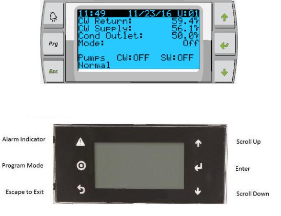
The three main interfaces supported will be the LCD display, referred to as the PGD1 or PLDPRO display, and the HMI touchscreen.
Figure 1: PGD1 Button Description
Alarm |
Scroll Up |
|
Indicator |
||
|
||
Program |
Enter |
|
Mode |
||
|
||
Escape to |
Scroll Down |
|
Exit |
||
|
Figure 2: PLDPRO Button Description
1
PGD1 and PLDPRO NAVIGATION
Enter Button
The PGD1 controller screen will automatically boot up to the Main screen. This screen allows you to enable or disable the chiller by pressing the Enter button. Pressing the Enter button will take you to the area of screen you wish to modify. Press multiple times if required.
Scroll Up/Down Buttons
This button will be used to modify the value such as temperature setpoint or probe adjustment values. The Scroll Up or Scroll Down button will also navigate you from page to page of the controller. The flashing cursor must be in the upper left-hand corner for the page navigation. Pressing enter repeatedly will move it to that location.
Esc Button
The Esc button is used to exit your present screen and take you back one screen. Pressing it multiple times will take you back to the Main screen.
Prg Button
This button takes you to the system menus. Once at the menus, use the scroll buttons to scroll through the various options. Pressing enter will select that menu item.
Alarm Button
This button will flash red if there is an active alarm. Pressing this button will take you to the active alarm screen to display the alarm. Once in the alarm screen, use the up/down buttons to scroll through alarms. The Alarm screen captures a snapshot of the system parameters at the time of the fault. Press and hold the Alarm button for 3 seconds to clear the active alarm if the fault has been corrected.
2
TOUCHSCREEN NAVIGATION
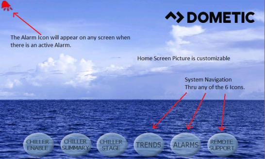
MAIN PAGE
Figure 3: Main Page
Chiller Enable
Touching this icon will take you to the chiller operational screen, where you can enter setpoints for both heating and cooling and monitor chilled water temperatures and pump current information.
Chiller Summary
Touching this icon will take you to the summary screen, where you can see the state of your HP, LP and FS and view your stage supply water temperature out for all available stages. Touching a stage on the screen will take you to that chiller stage for additional information.
Chiller Stage
Touching this icon will take you to the first stage, where the system refrigerant circuit and chilled water circuit can be monitored. This screen has multiple hotspots where all stage parameters can be viewed. If the system has the installed option, additional available hotspot icons will appear to view additional information. Forward and back buttons will navigate to the next stage.
Trends
Touching this icon will take you to the trending screen where you can view graphically how your system has been performing. The graph data is downloadable to a USB stick. Water temperatures and pressures as well as compressor current are available for graphing.
Alarms
Touching this icon will take you to the active alarm screen where alarms can be reviewed and cleared. Alarm history can also be viewed from here by using the navigation buttons on the top that take you to the alarm history. Using the drop-down menu will allow you to go back from minutes to months in the fault history. There is also an information icon that will take you to a help screen to display the possible causes of your alarm to aid in the troubleshooting of your system
Remote Support
Touching this icon takes you to the screen where you can enable a third party to view your system over an Internet connection via a VNC (Virtual Network Computing) server.
3
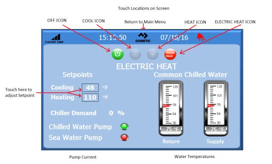
Figure 4: Touch Locations on Screen
Logo
The touchscreen logo is customizable. Pressing the logo will return you to the Main menu screen from any sub-screens. Some screens contain pop-up screens with information. To exit a pop-up, simply touch the X to close the screen.
Off Icon
Off icon will be illuminated only if the system is in a run state. Touch the Off icon to turn off the system.
Cool Icon
Cool will be illuminated only if the system is in cooling. Touch this icon to put the system in cool mode and the word cool will appear on the screen.
Heat Icon
Heat will be illuminated only if the system is in heating. Touch this icon to put the system in heat mode and the word heat will appear on the screen.
Electric Heat Icon
Only visible if option is installed. Electric Heat will be illuminated only if the system has electric heat enabled. Touch this icon to put the system in heat mode and the word heat will appear on the screen.
Setpoint Thermometers
These icons are touched to adjust the cooling or heating set points.
See Appendix 1 for complete touchscreen navigation.
4
GENERAL
The VARC chiller is a PLC based control system that uses a PID control loop to manage the capacity requirements of the system. This control loop allows for finite control to match the capacity of the chiller to the thermal load demand on the system. This system differs greatly from the on/off control of a standard chiller system, as it will modulate the speed of the compressor to increase or decrease its capacity allowing for reduced current consumption by the electrical system.
The chiller system will come programmed from the factory with the options enabled for that system. Although the system offers flexibility, these options can only be enabled by a factory representative.
The user will be able to select between Normal, Econo and Boost mode operation in single stage configuration. In a multistage configuration the user will also be able to select between Normal or Accelerated startup to bring the system chilled water temperature down faster or in the case of heat mode temperature higher.
The VARC controller is internally grounded with isolation between inputs and outputs. Additionally, the output relays offer double isolation so that different voltages can be used for groups of relays.
The system will utilize various sensor types for measuring analog temperatures and pressures. For temperature measurements, the system will use NTC type 10K@77° thermistors. Pressure transducers are ratiometric 0-650 PSI (45 bar) range for both suction and discharge monitoring.
DIGITAL INPUTS
Digital inputs are used to monitor the status of the protection circuits for the system.
Safety Inputs
All discrete inputs will be checked before the system will be enabled. Any faults detected on start-up must be verified and cleared via the VARC before system will start normal operation.
Chilled Water Flow Switch
With the system in either heating or cooling mode the Flow switch must be closed prior to system starting or a stage being enabled. In operation if Flow is lost for more than 10 consecutive seconds, the compressor or heat relay will be disabled. A flow switch fault will be recorded and displayed.
A CW Flow fault will be recorded and system will be in lockout and a manual restart will be required. The VARC will not allow the compressor or electric heat relay to be energized for the stage that has lost flow or the whole system if a common flow switch is being used.
Fault must be manually acknowledged via the VARC and cleared prior to re-enabling the system or stage.
Refrigerant High Side Pressure Limit
The VARC will immediately acknowledge an open circuit if the HI pressure switch is tripped and de-energize the compressor. It will record and display high pressure fault on the alarm screen. If the VARC detects a high pressure fault during operation, a HP fault will be displayed and recorded. The VARC will not allow the compressor relay to be re-energized, until switch is in the closed position.
The fault must be manually acknowledged via the VARC and cleared prior to re-enabling the system or stage.
ANALOG INPUTS
High Limit Temperature Setpoint
The high limit temperature sensor is continuously monitored whether in Cooling, Reverse Cycle or Electric Heat mode.
This sensor is used to detect a high temperature condition in the supply water from the chiller. If the chilled water temperature is sensed to be greater or equal to 125°F (51.7°C), all enabled compressor relays will be de-energized, turning off the compressor(s) if operating in reverse cycle mode. If electric heat is being used, all enabled heater relays will be de-energized, turning off the heating element(s).
5
As the temperature falls, the compressor or electric heat relay will re-energize when the temperature reaches 110°F (43.3°C).
A high temperature fault will be recorded and displayed if the system exceeds the alarm set point. In a high temperature situation, VARC will not allow the compressor or electric heat relay to be energized. The fault must be manually acknowledged on the active alarm screen and cleared prior to re-enabling the system or stage.
If a temperature sensor is bad or not connected, the VARC will display an alarm for that sensor.
Freeze Temperature Setpoint
The low limit temperature sensor is continuously monitored whether in Cooling, Reverse Cycle or Electric Heat mode.
This sensor is used to detect a freeze condition in the supply water of the chiller. If the chilled water temperature is sensed to be equal to or less than 38°F (3.3°C), then the compressor relay will be de-energized, shutting off the compressor. As the temperature rises, the compressor relay will re-energize when the temperature reaches 42°F (5.6°C).
A low temperature fault will be recorded and displayed if the system falls below the alarm set point. In a low temperature situation, VARC will not allow the compressor or electric heat relay to be energized. The fault must be manually acknowledged on the active alarm screen and cleared prior to re-enabling the system or stage.
If a temperature sensor is bad or not connected, the VARC will display an alarm for that sensor.
Condenser Freeze Protection
The system is equipped with a temperature sensor mounted to the condenser coil. This sensor is there to sense the coil temperature. In heat mode if the coil temperature drops below 40 °F, the VARC controls will automatically lower the speed of the compressor to half the speed that it was currently running. The display will indicate “Freeze Defrost” while performing this operation.
PRESSURE TRANSDUCERS
Suction Pressure
The suction pressure is continuously monitored by the VARC. If the suction pressure is below the alarm set point for longer than the programmed time delay, a fault will occur. This low suction fault will be recorded and displayed on the alarm screen.
The fault must be manually acknowledged via the VARC and cleared prior to re-enabling the system or stage.
Discharge Pressure
The discharge pressure is continuously monitored by the VARC. If the discharge pressure is above the alarm set point for longer than the programmed time, a fault will occur. This high pressure fault will be recorded and displayed on the alarm screen.
The fault must be manually acknowledged via the VARC and cleared prior to re-enabling the system or stage.
RELAY OUTPUTS
COMP – Compressor
VARC COMP output will provide switched power to the VFD enable pin for the compressor normal operation.
CWP – Chilled Water Pump
VARC CWP output will provide switched power to the contactor coils for the chilled water pump.
SWP – Sea Water Pump
VARC SWP output will provide switched power to the contactor coils for the sea water pump.
RV – Reversing Valve
VARC RV output will provide switched power to the coils for the reversing valve.
EH – Electric Heat
VARC EH output will provide switched power to the contactor coils for the electric heat.
6
Fault
Provides a Normally Open (NO) contact point. Any fault condition will close the NO contact. This output can be used to power a light, relay, or interface to a ship’s monitoring system. The output on this terminal will be 230 VAC.
SYSTEM OVERVIEW
System Power-up
Software Revision
Upon applying power to the system, the display will indicate the software revision number or display it on the main status screen.
VARC is enabled and waiting for user selection.
MODBUS
The VARC comes with a 3 wire Modbus connection as part of the electrical box. This connection is used for multistage configuration, touchscreen and networking to a boat management system.
Startup
The VARC Chiller controller can be operated as a single or a multistage chiller plant. During initial setup, the system will be configured for the number of stages and the available options. System is set for Return water control but can be modified for Supply water control if needed. The user has the option to select between metric values being displayed or Imperial values being displayed during operation of the system.
In a multistage configuration the user will be able to change the different operating startup modes. The two startup modes are: normal stage startup or accelerated mode startup. The normal startup is when the system has a time delay between the staging up of the various stages. Stage one will be initiated and will start its operation once the PID determines that more capacity is required the second stage will be initiated. While in operation and the system has maintained the chilled water loop and the PID has determined that that no additional stage is required or has met capacity demand it will reduce the speed of the compressors. The compressors will operate at minimal speed to maintain the chilled water loop. If the speed of the compressor still exceeds the demand the stage with the most run hours will be turned off.
The VARC chiller allows the user to select between three operating modes. Econo mode, normal mode and boost mode. These three modes allow the user to have predefined current limits. The economy mode is the energy efficient mode where the compressor is limited to default five amp configuration. The normal mode is the typical mode of operation where the current limit is set to 9 Amps for both heat and cool modes. The boost mode allows the system to run at maximum capacity without current limitation other than the full limits of the frequency drives which is 12 amps.
Chilled water setpoint will be entered for Cool and Heat mode.
Once enabled, CW and SW pumps will be turned on for operation.
Operational Checks
Once the VARC is enabled the system will conduct pre-startup checks. The VARC program will check all CW flow switches for faults. The VARC will also check HP and LP (optional) switches for faults.
Individual stage faults will only disable that stage.
Compressor Startup
The VARC utilizes a BLDC compressor that is capable of operating at a very high frequency. This requires that the compressor have a ramped startup to establish proper lubrication as to not damage the compressor. This startup has a ramp time and a minimal speed operation that will last for 100 seconds to allow the compressor to properly warm-up before operating at maximum speed.
The compressor minimum on time is 100 seconds and minimum off time is also 100 seconds with a minimum time between starts of 120 seconds. These default parameters allow the compressor to operate in a safe mode that will not damage the compressor.
7
SETPOINTS
Cooling
Cooling setpoint is a VARC adjustable parameter from 42°F (5.56°C) (for Supply control and 48°F Return control) to 55°F (13°C) in one degree increments. To adjust the cooling setpoint, simply touch the VARC screen and change to desired new setpoint. In cooling mode, you will not be able to enter a number outside of this range.
Heating
Heating setpoint is a VARC adjustable parameter from 100°F (38°C) to 114°F (45.56°C) in one degree increments. To adjust the heating setpoint, simply touch the VARC screen and change to desired new setpoint. In heating mode you will not be able to enter a number outside of this range.
Compressor Staging Time
Compressor staging time is a VARC adjustable parameter where 2 modes are selectable between normal and accelerated staging. The accelerated staging is only available in a multistage configuration. The normal staging works the same as the on off system where there is a time delay between the multiple stages driven by the PID loop. The accelerated staging is only available during initial startup in a multistage configuration. This accelerated startup is when all available stages are turned on simultaneously. The stages will start the ramp-up process at the same time after the fixed startup delay. After this delay the units will ramp the maximum speed to achieve maximum capacity.
Run Mode – Cooling
Compressor rotation is active during run mode. The compressor with the lowest running hours will be enabled first and compressor with the highest running hours will be disabled first.
First stage will be enabled and the compressor will start after CW and SW flows are stable for 10 seconds (default).
First stage will continue to run for 1 minute before enabling the next stage. If the PID loop requires demand, then the next stage will be enabled with a startup delay of 3 minutes before running up to required speed.
Run Mode – Reverse Cycle Heating
Compressor rotation is active during run mode. The compressor with the lowest running hours will be enabled first and compressor with the highest running hours will be disabled first.
Enable Reverse Cycle Heat only for the system.
First stage heating will be enabled and the compressor will start after CW and SW flows are stable for 10 seconds.
First stage will continue to run for 5 minutes before enabling the next heater stage. If the PID loop requires demand, then the next stage will be enabled with a startup delay of 3 minutes before running up to required speed.
Run Mode – Electric Heating (optional heater barrel)
Heater rotation is active during run mode. The heater with the lowest running hours will be enabled first and the heater with the highest running hours will be disabled first.
Enable Electric Heat only for the system.
First stage will be enabled and the electric heater will start after CW flow is stable for 10 seconds.
First stage will continue to run for 5 minutes before enabling the next heater stage. If the PID loop requires demand then the next stage will be enabled.
OPERATIONAL MODES
PUMP OPERATION
8
Chilled Water Pump
The chilled water pump relay shall close if the system is in heat mode or cool mode. The pump will be enabled 5 seconds prior to the first stage being enabled. Pump will be on for continuous operation when system is enabled
Sea Water Pump
The sea water pump will have a selectable operating mode between continuous operation or cycle with compressor operation. The default configuration is to cycle with the demand.
The sea water pump relay shall close 5 seconds before the compressor starts in heating or cooling modes and will open 5 seconds after the last compressor cycle is completed. If immersion heating is available and used, the sea water pump will be disabled.
In a multistage configuration the pump outputs can be daisy chained at the back of the unit to supply power to the pumps. This will allow any stage to supply power to the pumps when being staged on and off and as a redundant control for the pumps.
Cooling Mode
Cooling mode is entered when Cool is selected on the touchscreen or with the display buttons. The system will automatically start cooling depending on temperature setpoint. The pumps will operate as described in the pump operation section.
oThe board will energize the compressor relay if return water/supply water temperature is above the cooling setpoint and the staging delay has elapsed.
oThe compressor will continue to run until the cooling setpoint has been reached or an alarm condition exists. A stage will have a minimum run time of 100 seconds before it can be turned off and a minimum off time of 120 seconds before it can be re-enabled. This minimum on time is required to ensure that the system is not cycling on and off and not allowing the compressor to properly warm-up. This ensures proper oil lubrication of the system
o |
If the system calls for a stage to be toggled on/off, the next available stage will be used that meets the staging criteria. |
o Load shedding will occur in multistage operation when approaching chilled water setpoint. |
|
o |
The reversing valve is toggled to relieve head pressure at the end of a compressor run cycle. |
Heating Mode
Reverse Cycle Heating mode is entered when Heat is selected on the touchscreen or with the display buttons. The system will automatically start heating depending on the temperature setpoint. The pumps will operate as described in the pump operation section.
o The reversing valve relay will be energized to change the unit to operate in Reverse Cycle Heating mode.
oThe VARC will energize the compressor relay if return/supply water temperature below the programmed heating setpoint and the staging delay has elapsed. The compressor will continue to run and the reversing valve will remain energized until the heating setpoint has been reached or an alarm condition exists. As setpoint is reached, the compressor will reduce its speed to maintain the water temperature. Once it has reached temperature and a hysteresis of 1 degree the unit will turn off the
compressor. Once it has turned off the compressor the reversing valve will deenergize after a 2-second delay.
oA stage will have a minimum run time of 3 minutes before it can be turned off and a minimum off time of 3 minutes before it can be re-enabled. If the system calls for a stage to be toggled on/off, the next available stage will be used that meets the staging criteria.
Electric Heating mode is entered when Electric Heat is selected on the touchscreen or with the display buttons. The system will automatically start heating depending on the temperature setpoint.
oThe VARC will energize the heater relay if return/supply water temperature is below the programmed setpoint and the staging delay has elapsed in a multistage configuration.
9
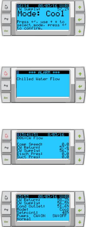
Status Screen Navigation
The main home screen is the status screen where the single stage operation can be reviewed or in a multistage configuration the user can scroll and see the values of the chilled water and other parameters of the additional stages. The user will simply use the down arrow key to scroll through the various parameters being displayed on the LCD screen. The LCD screen will also indicate on the main screen the mode of operation whether it is Econo or Normal mode.
Figure 5:
The main screen will also indicate if there is an alarm present on the system by flashing the word alarm in the lower right-hand corner. The smaller PLD Pro LCD screen also has an audible tone that you will hear when there is an alarm present on the system as well as display the word alarm in the lower right-hand corner.
Figure 6:
The alarm logger is used to see the alarm history and displays the compressor speed, the CW return & supply temperature, the discharge & suction pressure.
Figure 7:
The main screen will indicate the chilled water return temperature the chilled water supply temperature as well as the condenser outlet temperature which is the freeze control indicator for the condensers in heat mode.
Figure 8:
10
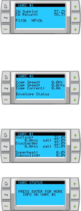
The additional screens following the main screen will contain information per Stage. The first screen includes the CW Supply & Return temperature, flow switch and high pressure Ok or Alarm.
Figure 9:
The next screen you are able to read compressor speed also contains information to let you know if the system is in a safety count down. Once this time has elapsed and other time delays have been met the system will start up. At the bottom of the screen the unit will display the envelope status for the operation of the compressor. The envelope status basically tells you if the unit is functioning within the control parameters for suction and discharge. If the system has a problem controlling the envelope the message will be displayed at the bottom of that screen.
Figure 10:
The next screen will contain the suction pressure information the discharge pressure information as well as the superheat and sub-cooling values being calculated by the system.
Figure 11:
The following screens contain the drive status, to access them press enter:
Figure 12:
Figure 13:
11
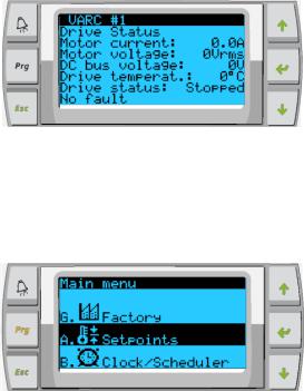
The final screen will contain the image of the refrigerant circuit and contain the valve position information.
To change the setpoint of the chilled water. The user must press the program button and scroll to Menu item B. Setpoint. The password prompt will be displayed and 1234 must be entered to have access to change the value from the default.
Figure 14:
Main Menu Items: Screen Navigation Tree
Press enter to select items to view and up/down the screen will automatically return to the main status screen.
Menu A: On/Off Unit
o |
Unit Address: |
1 (Default) |
o |
Power By Display: |
ON (Default) |
o |
Status: |
Unit ON |
Menu B: Setpoints: Password required (1234) |
||
o |
Heating Setpoint |
110 (Default) |
o |
Cooling Setpoint |
48 (Default) |
Current Limiting: |
|
|
o |
Mode: |
Normal (Default) Econo or Boost |
o |
Econo: |
4 Amps |
o |
Normal: |
9 Amps |
Configuration: |
|
|
o |
Temperature Units: |
F (Default) Or C |
o |
Pressure Units: |
PSI (Default) or Bar |
Menu C: Clock/Scheduler
12
o |
Date: |
|
Change date here. |
o |
Hour: |
|
Change time here. |
o |
Day: |
|
Displayed |
Next Screen: |
|
|
|
o |
DST: |
|
Enabled (Default) |
o |
Description Follows: |
|
|
Menu D: Input/Output |
View values or status of analog sensors, digital inputs or relay outputs. |
||
o |
A: Analog Inputs: |
|
|
|
o |
CW Return |
|
|
o |
Input B001: |
Actual Value |
|
o Scroll for additional sensor values with down arrow button then ESC to exit. |
||
o |
B: Digital Inputs: |
|
|
|
o |
Flow Switch |
|
|
o |
DI 3 Status: |
Actual State (Open or Closed) |
oScroll Down for additional active digital inputs. This will change depending on what is enabled in the system configuration.
o C: Relay Outputs: o SW Pump
o Relay 1 Status: Actual State (ON or OFF)
oScroll Down for additional active relay outputs. This will change depending on what is enabled in the system configuration.
o D: Analog Outputs:
o NOT USED
Menu E: Alarm History
Will capture the status of the following parameters at the time of the alarm. The most recent alarm will be shown. Use up arrow to to view previous alarms.
o Alarm will be displayed followed by:
o |
Comp Speed: |
Actual value |
o |
CW Return: |
Actual value |
o |
CW Supply: |
Actual value |
o |
Discharge Pres: |
Actual value |
o |
Suct Pres: |
Actual value |
Menu F: Board Switch
This menu allows you to change to view additional boards and make changes to that particular board. This only applies to a multi-stage configuration when units are networked together.
o |
Unit Address: |
1 (Default) |
o |
Switch to unit: |
Desired board address |
Menu G: Technician
Some subscreens will require a password. Please contact Dometic for service password.
Submenus:
13
Sub Menu A: Information
o The service contact information is available on this screen. o Scroll to view additional firmware information.
o The next screen will contain the flash RAM information.
oThe next screen will contain the power cycle status which indicates how many days the unit has been running in the last time it was turned off or on.
o The next screen will contain the Evo firmware information.
o The next screen will show the power plus firmware information.
Sub Menu B: Commission
oOn this screen the technician will be able to enter the dealer contact information. The default contact information is the Dometic contact information. Then the user will select to update the information by selecting yes at the prompt.
oThen scroll to the next screen. On the screen the user will be asked to commission the system and must select between yes or no then press enter. This will save the information and once commissioned cannot be changed.
Sub Menu C: Working Hours
o |
Compressor |
|
o |
Run hours: |
Actual |
o |
Num Starts: |
Actual |
Scroll to next screens to view pump and electric heat hours (optional if installed).
Sub Menu D: BMS Config
Used only for configuration system to work with STIIC network.
o BMS Port 1
o Protocol: Carel Next screen
o |
BMS Port 1 |
|
|
|
o |
Adddress |
1 (Default) |
|
|
o |
Baud Rate |
2400 (Default) |
|
|
Sub Menu E: Service Settings |
|
|
||
|
Sub Menu A: Working Hour Set |
|
||
|
o |
Compressor |
|
|
|
o |
Service Set Point: |
0000h (Default) |
Can be used to set a service interval for system. Will display |
|
|
message on screen. |
|
|
|
o |
Reset to Zero? |
NO (Default). |
Used to reset the run hours |
|
o |
Run hours: |
Actual Value. |
Used to set the run hours if compressor or board has been |
|
|
replaced. |
|
|
Scroll to view additional items such as the pumps and electric heat if installed.
Sub Menu B: Probe Adjustment
To be used for calibrating the installed temperature sensors or pressure transducers.
14
o |
CW Return |
|
o |
Input B001 |
|
o |
Offsett |
0.0 (Default) |
o |
Value |
Actual Value |
Scroll to view additional analog sensors for calibration.
Sub Menu C: Control Loops
This menu allows you to set the superheat setpoint and other PID parameters for the valve and drive.
NOTE: Do not make changes to the PID loops.
o |
Superheat |
|
o |
Cool Setpoint: |
10 F (Default) |
o |
Heat Setpoint: |
10 F (Default) |
Next screen |
|
|
o |
Setpoint SH: |
10K (Default) |
o |
LowSH thresh: |
2.0K (Default) |
o |
LOP thresh: |
-50.0 C (Default) |
o |
MOP thresh: |
26.0 C (Default) |
Next screen |
|
|
Modulating Setup (PID) |
|
|
o |
Compressor |
|
o |
Input |
Actual Value |
o |
Output |
Actual Value |
o |
Setpoint |
8.9 (Default) |
o |
Band: |
11.0 (Default) |
o |
Integration Time: |
20 (Default) |
Sub Menu D: User Save
This is used to save any user specific settings.
o |
Save? |
No (Default) Yes |
o |
Restore? |
No (Default) Yes |
o |
Enable Auto Save: |
Yes (Default) No |
Next screen
This will clear the Alarm History. This is only to be used once the unit has been commissioned.
o Continue? |
No (Default) Yes |
Sub Menu E: Stage Address
This menu is to be used in a multistage configuration to change the additional unit addresses. This is to be done so that there are no address conflicts when daisy chaining the additional unit mod bus connections. This must be done prior to connecting all the units together, via Modbus connections.
o pLAN Board Addressing
15
o |
Current Address: |
1(Default) |
o |
Change Address to: |
1(Default) |
Next Screen |
|
|
o |
Unit Settings |
|
o |
Num of Stages |
1 (Default) Max 4 |
Sub Menu: F Stage Disable
This menu is to be used when in a multistage configuration. This allows a technician to take a stage off-line so that repairs can be made and the rest of the system be operational in auto mode. The system must be in an off state to enable stage control. Disabling a stage via breaker will cause system to go into a “Limp Mode”.
o |
Maintenance |
|
|
o |
Stage Control: |
No (Default) Yes. |
|
If Enabled, |
|
||
|
o |
Stage 1: |
Enabled (Default) Disabled |
|
o |
Stage 2: |
Enabled (Default) Disabled |
|
o |
Stage 3: |
Enabled (Default) Disabled |
|
o |
Stage 4: |
Enabled (Default) Disabled |
Sub Menu F: Manual Management
This menu allows the technician to manually operate the relay outputs as well as enable or disable analog sensors.
o Sub Menu A: Analog Input |
|
|
o |
CW Return |
|
o |
Manual Control B001: |
Off (Default) On |
o Manual Position: Value Desired |
||
o |
Value: |
Actual Value |
Scroll to adjust additional sensors |
||
o Sub Menu B: Digital Input |
|
|
o |
Flow Switch |
|
o |
Manual DI 3: |
Off (Default) ON |
o |
Manual Position: |
Actual (Enter Desired Position) |
o |
DI Input Status: |
Actual Value |
Scroll to adjust additional inputs |
|
|
o Sub Menu C: Relay Output |
|
|
o |
SW Pump |
|
o |
Manual Relay 1: |
OFF (Default) No |
o |
Manual Position: |
OFF (Enter Desired) |
o |
Relay Status: |
Actual Posi in tion |
Scroll to adjust additional Outputs |
||
o Sub Menu D:Analog Outputs |
|
|
o |
NOT USED |
|
16
Electrical Specifications
Line Voltage |
208 To 240 VAC |
Frequency |
50 or 60 Hz |
Phase |
1 ph |
Chilled Water Pump Output |
12 Amps @ 230 V |
Sea Water Pump Output |
12 Amps @ 230 V |
VFD Input |
22 Amps @ 230 VAC |
VFD Output |
12 Amps @ 230 V |
Max Breaker |
25 Amps @ 230 VAC |
Note: Increase breaker size to include pump current if running pumps directly off system. |
|
Maximum Ambient Operating Temperature |
140°F (60°C) |
Maximum Rh Conditions |
99% Non-Condensing |
Installation Requirements:
Follow Standard Chiller Installation manual. In addition a recommended 8 to 10 inches keep out from the back of the unit in case the VFD must be removed.
17

Appendix I: Touchscreen Navigation
MAIN PAGE
Figure 15
CHILLER ENABLE
Figure 16
18
CHILLER SETPOINTS
Figure 17
19
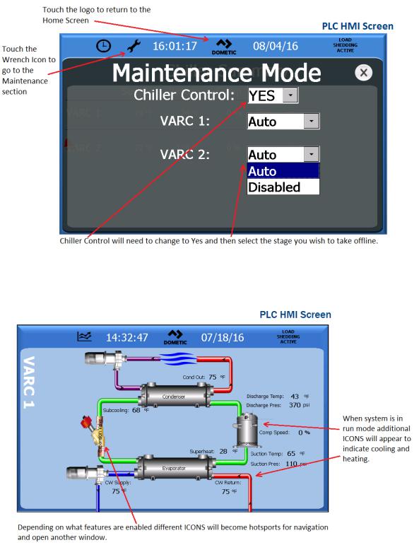
Figure 18
CHILLER STAGE
Figure 19
20
 Loading...