


SI 1500 – 12V/24V
Pure Sine Wave Inverter
230Vac from 12Vdc / 24Vdc source
User’s Manual / Benutzerhandbuch / Manuel de l©utilisateur
Användarhandbok / Manuale d©uso / Manual del usuario

Dometic SI 1500
Pure Sine Wave Inverter
230Vac from 12Vdc / 24Vdc source
User’s Manual

Welcome to the Dometic world
Dometic Pure Sine wave Inverters – A sign of comfort
The SI 1500 Inverter is designed as a stand –alone power inverter.
This Inverter is extremely suitable for demanding RV, Commercial Vehicle, and Marine appliances.
With its advanced power saving features you will enjoy the freedom mobile power wherever you go!
You have made a wonderful choice to use Inverters from Dometic. Feel free to contact our dealers for more information or more recommendations within mobile power supply.
Best regards,
Dometic

Table of Contents
1 |
Important Safety Instructions ............................................................. |
1 |
|
|
1.1 |
General Safety Precautions ........................................................ |
1 |
|
1.2 |
Precautions When Working with Batteries .................................. |
1 |
2 |
Features ............................................................................................ |
2 |
|
|
2.1 |
Application .................................................................................. |
2 |
|
2.2 |
Electrical Performance................................................................ |
3 |
|
2.3 |
Mechanical Drawings.................................................................. |
4 |
3 |
Introduction........................................................................................ |
5 |
|
|
3.1 |
Front Panel Operation ................................................................ |
5 |
|
3.2 |
Rear Panel Operation : ............................................................... |
6 |
|
3.3 |
Installation .................................................................................. |
7 |
|
3.4 |
Quick hoop-up and testing:......................................................... |
8 |
|
3.5 |
Making DC Wiring Connections .................................................. |
10 |
|
3.6 |
Inverter Operation....................................................................... |
12 |
|
3.7 |
Power output .............................................................................. |
14 |
4 |
Troubleshooting guide ....................................................................... |
15 |
|
5 |
Maintenance ...................................................................................... |
17 |
|
6 |
Warranty ............................................................................................ |
17 |
|
7 |
Appendices C .................................................................................... |
18 |
|
|
7.1 |
Remote control operations:......................................................... |
18 |
|
7.2 |
Power saving mode .................................................................... |
20 |
© Copyright: This manual is the copyright of DOMETIC and may not be reproduced or copied without the express permission of the owner.

1 Important Safety Instructions
WARNING !
Before you install and use Your Dometic SI 1500 Sine Inverter, be sure to read and follow these safety instructions. Save this for later reference.
1.1General Safety Precautions
1-1-1. Do not expose the SI 1500 Sine Inverter to rain, snow, spray, bilge or dust. To reduce risk of hazard, do not cover or obstruct the ventilation openings. Do not install the SI 1500 Sine Inverter in a zero-clearance compartment. Overheating may result.
1-1-2. To avoid the risk of fire or electric shock, make sure that existing wiring is in good electrical condition and that wire size is not undersized. Do not operate the SI 1500 Sine Inverter with damaged or substandard wiring.
1-1-3. This equipment contains components which can produce arcs or sparks. To prevent fire or explosion do not install in compartments containing batteries or flammable materials or in locations which require ignition protected equipment. This includes any space containing gasoline-powered machinery, fuel tanks, or joints, fittings, or other connections between components of the fuel system.
1.2Precautions When Working with Batteries
1-2-1. If battery acid contacts skin or clothing, wash immediately with soap and water. If acid enters eye, immediately flood eye with running cold water for at least 20 minutes and get medical attention immediately.
1-2-2. NEVER smoke or allow a spark or flame in vicinity of battery or engine.
1-2-3. Do not drop a metal tool on the battery. The resulting spark or short-circuit on the battery or other electrical part may cause an explosion.
1-2-4. Remove personal metal items such as rings, bracelets, necklaces or watches when working with a battery. A battery produces a short-circuit current high enough to weld a ring or other metal, causing a severe burn.
1

2Features
 Pure sine wave output (< 3% THD)
Output frequency : 50Hz
Low power “ Power Saving Mode “ to conserve energy or battery.
RS – 232C interface / remote controls port.
Built–in voltage and watt meter.
Thermostatically controlled cooling fan
Advanced microprocessor
Protection : Input low voltage, Overload, Short circuit, Low battery alarm, Input over voltage and over temperature
2.1Application
2-1-1. Power tools, circular saws, drills, grinders, sanders, buffers, weed and hedge trimmers, air compressors.
2-1-2. Office equipment, computers, printers, monitors, facsimile machines, scanner.
2-1-3. Household items, vacuum cleaners, fans, fluorescent and incandescent lights, shavers, sewing machines.
2-1-4. Kitchen appliances, microwave ovens, refrigerators and freezers, coffee makers, blenders, ice makers, toasters.
2-1-5. Industrial equipment, metal halide lamp, high-pressure sodium lamp.
2-1-6. Home entertainment electronics, television, VCRs, video games, stereos, musical instruments, satellite equipment.
2

2.2Electrical Performance
Specification |
|
Model No. |
||
Item |
SI 1500 24Vdc - 230Vac |
|
SI 1500 12Vdc - 230Vac |
|
|
|
|
|
|
Continuous Output Power |
|
1500W |
||
|
|
|
||
Surge Rating |
|
2000W |
||
|
|
|
|
|
Input Voltage |
24V |
|
12V |
|
|
|
|
|
|
Output Voltage |
|
230V ± 3% |
||
|
|
|
|
|
Frequency |
50 Hz +/- 0.05% |
|||
|
||||
|
|
|
|
|
Peak Output Current |
11A |
|
11A |
|
|
|
|
|
|
Efficiency (full load) |
89% |
|
86% |
|
|
|
|
||
No Load Current Draw |
1.5W Saving Mode |
|||
|
|
|||
Output Waveform |
Sine Wave <3% THD |
|||
|
|
|||
Output Voltage Regulation |
230V RMS –10%/+4% |
|||
|
|
|
|
|
Input Voltage Regulation |
20-32VDC |
|
10-16 VDC |
|
|
|
|
||
Protection |
Overload, Short Circuit, Reverse Polarity (Fuse), |
|||
Over/Under Input Voltage, Over Temperature. |
||||
|
||||
|
|
|
|
|
Recovery Time from Power |
|
5 Seconds |
||
Saving mode |
|
|||
|
|
|
||
|
|
|
||
Interface Control Port |
|
RS-232C |
||
|
|
|
||
Remote Control Unit |
|
Optional |
||
|
|
|
||
Safety |
|
EN60950 |
||
|
|
|
|
|
|
EN50081-1:1992 |
|
|
|
|
EN50082-1:1992 |
|
|
|
EMC |
EN55022B:1994 |
|
e-Mark |
|
EN61000-4-2:1995 |
|
e13-020932 |
||
|
|
|||
|
EN61000-4-3:1996 |
|
|
|
|
ENV50204:1995 |
|
|
|
|
|
|
||
Operating Temperature Range |
-25 to +40 Celsius |
|||
|
|
|||
Storage Temperature Range |
-30 to 70 Celsius |
|||
|
|
|||
Dimensions |
390 (L) x 275 (W) x 105 (H) mm / 15.4 (L) x 10.8 (W) x 4.1 (H) Inch |
|||
|
|
|||
Cooling |
Thermostatically controlled cooling fan |
|||
|
|
|||
Weight |
7.0kgs / 15.5 lbs. |
|||
|
|
|
||
IP Class |
|
IP 23 |
||
3

2.3Mechanical Drawings
PURESINEWAVE230VAC50Hz |
1500W |
4

3 Introduction
This Dometic SI 1500 Sine Inverter is a member of the most advanced line of mobile AC power systems available. To get the most out of the inverter, it must be installed and used properly.
Please read and follow the instructions in this manual before installing and using this model.
3.1Front Panel Operation
3-1-1. Front view:
1500W
PURE SINE WAVE 230V AC 50 Hz
3-1-2. ON / OFF switch:
Power ON/OFF switch, leave in the OFF position during installation.
3-1-3. Power saving :
Power energy saving enable.
OVP : over voltage protection when on UVP : under voltage protection when on OTP: over temperature protection when on OLP : over load protection when on
Input volts : input voltage display indication battery voltage level
Load watts : AC load watts display.
5

3.2Rear Panel Operation :
3-2-1. Ventilation openings:
Do not obstruct, allow at least 25 mm for air flow.
3-2-2. Battery terminals:
Connect to 12Vdc/24Vdc battery or other 12Vdc/24Vdc power source. On the inverter red (+) is positive, black (-) is negative. Reverse polarity connection will blow the internal fuse and may damage the inverter permanently.
3-2-3. RS-232C:
Connect for remote control unit (option accessory)
3-2-4. Connect chassis ground terminal to earth or to vehicle chassis using 10 mm² wire.
WARNING !
Operation of the inverter without a proper chassis ground connection may result in an electrical safety hazard.
Before proceeding further, carefully check that the Dometic SI 1500 Sine Inverter is NOT connected to any batteries, and that all wiring is disconnected from any electrical sources. Do not connect the output terminals of the Dometic SI 1500 Sine Inverter to an incoming AC source, it may result in an electrical safety hazard and damage the Inverter.
6
3.3Installation Where to install
The inverter should be installed in a location that meets the following requirements:
3-3-1. Dry – Do not allow water to drip or splash on the inverter.
3-3-2. Cool – Ambient air temperature should be between -25°and +40°Celsius.
3-3-3. Safe – Do not install in a battery compartment or other areas where flammable fumes may exist, such as fuel storage areas or engine compartments.
3-3-4. Ventilated – Allow at least 25 mm of clearance around the inverter for air flow. Ensure the ventilation openings on the rear and bottom of the unit and the fan inlets are not obstructed.
3-3-5. Dust-free – Do not install the Dometic SI1500 Sine Inverter in a dusty environment where dust, wood particles or other filings/shavings are present. Dust can be pulled into the unit when the cooling fan is operating.
3-3-6. Close to batteries – Avoid excessive cable lengths but do not install the Dometic SI 1500 Sine Inverter in the same compartment as batteries. Use the recommended wire lengths and sizes. Do not mount the Dometic SI1500 Sine Inverter where it will be exposed to the gases produced by the battery. These gases are very corrosive and prolonged exposure will damage the Dometic SI 1500 Sine Inverter.
7
3.4Quick hoop-up and testing:
For a quick hook-up of the Dometic SI 1500 Sine Inverter to check its performance before going ahead with installation, please follow these guidelines:
3-4-1. Unpack and inspect the Inverter, check to see that the power switch is in the OFF position.
CAUTION ! 
Reverse polarity connection will blow a fuse in inverter and may permanently damage the inverter. Damage caused by reverse polarity connection is not covered by warranty.
3-4-2. Connect proper cables with fuse (see table 1) to the power input terminals on the rear panel of the inverter. First to the red positive terminal (+) and then to the black negative terminal(-). Tighten the cables securely.
WARNING !
Make sure the DC connections on the inverter are tight (torque to 9-10 ft-lbs, 11.7-13Nm). Loose connections will overheat and could result in a potential hazard.
3-4-3. Connect the red cable coming from the positive terminal on the inverter to the positive output on the battery or power source.
Before proceeding further, carefully check that cable you have just connected ties the positive terminal of inverter to the positive output terminal of battery or power source!
3-4-4. WARNING!
You may observe a spark when you make the next connection since current may flow to charge capacitors in the inverter. Do not make this connection in the presence of flammable fumes. Explosion or fire may result. Continue: Connect the cable from the negative terminal of the inverter to the negative terminal of the battery or power source. Make a secure connection.
8

3-4-5. Set the power switch to the ON position. Check the meters and indicators on the front panel of the inverter. The voltage bar graph should indicate 11 to 14 volts (22 - 28V when 24V version is used) depending on the voltage level of the power source. If there is no indication, check your power source and the connections to inverter.
The other indicators should be off.
3-4-6. Set inverter switch to the OFF position, the indicator lights may blink and the internal alarm may sound momentarily.
This is normal. Plug the test load (maximum 1500W resistive load) into the AC receptacle on the front panel of the inverter. Leave the test load switched off.
3-4-7. Set inverter switch to the ON position and turn the test load On. The inverter should supply power to the load. If you plan to accurately measure the true output r.m.s. voltage of inverter, a meter such as FLUKE 45, BECKMAN 4410 or TRIPLETT 4200 must be used. (True RMS multimeter must be used).
9

3.5 Making DC Wiring Connections
Follow this procedure to connect the battery cables to the DC input terminals on the Dometic SI 1500 Sine Inverter. Your cables should be as short as possible (less than 10 feet / 3 meters) and dimensioned to handle the required current in accordance with the electrical codes or regulations applicable to your installation. See table 1 for cable dimensions.
Cables that are not an adequate gauge (too narrow) or are too long will cause decreased inverter performance such as poor surge capability and frequent low input voltage warnings and shutdowns.
These low input voltage warnings are due to DC voltage drop across the cables from the inverter to the batteries. The longer and narrower these cables, the greater the voltage drop.
Increasing your DC cable size will improve performance. The producer recommends the following cables for optimum inverter performance, see table 1 and drawing:
Model No |
Wire |
Inline Fuse |
|
|
|
SI 1500-12V |
35mm2, AWG2 |
200A |
SI 1500-24V |
22 mm², AWG4 |
130A |
|
|
|
Also, use only high quality copper wiring and keep cable length short, we recommend less than 3 meters / 10 feet.
10
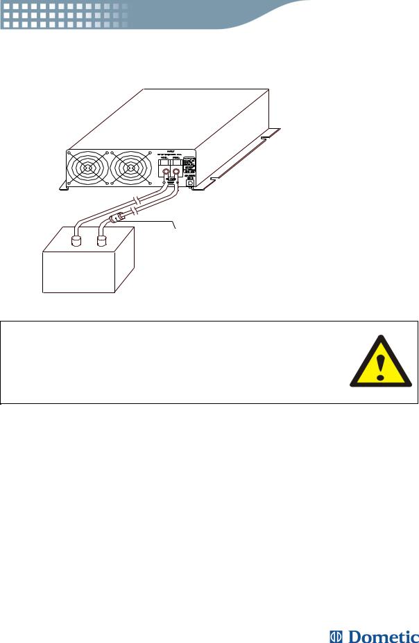
S 1 5 0 0
IN L IN E F U S E
-+
B A T T E R Y
WARNING !
Failure to place an in-line fuse on the “+” cable running between the inverter and battery may cause damage to the inverter and will void warranty.
11

3.6Inverter Operation
To operate the inverter, turn it on using the ON/OFF switch on the front panel. The inverter is now ready to deliver AC power to your loads. If you are operating several loads from the inverter, turn them on separately, one by one, after the inverter has been turned on. This will ensure that the inverter does not have to deliver the starting currents for all the loads at once and give you a problem free performance.
3-6-1. Controls and indicators:
The ON/OFF switch turns the control circuit in the inverter on and off. It does not disconnect input voltage from the inverter. The Dometic SI1500 Sine Inverter operates from an input voltage ranging from:
10.5 to 15.0 VDC for 12V models,
20 to 32Vdc for 24V models
The Dometic SI 1500 Sine Inverter will indicate high and low DC voltage conditions as follows :
Table 2
Model |
DC Input over |
DC Input under |
DC Input under |
|
voltage shut-down |
voltage alarm |
voltage shut-down |
|
|
|
|
SI 1500-12V |
16.7VDC |
10.2VDC |
9.5VDC |
|
|
|
|
SI 1500-24V |
33.4VDC |
20.4VDC |
19.0VDC |
|
|
|
|
3-6-2. Battery voltage indicator:
The battery voltage bar graph indicates the voltage level at the input terminals of the inverter. At low input current, this voltage is very close to the battery voltage. At high input current, this voltage will be lower than the battery voltage because of the voltage drop across the cable and connections. Ideally, the voltage should remain in the green areas of the bar graph. If the voltage goes into the red area at top and bottom of the graph, inverter may shutdown.
12

3-6-3. The AC load watt bar graph indicates the power drawn from the inverter. For long term operation, the watt indicator should remain in the green and orange area of the bar graph.
Short term operation is possible with watt indicator in the red area.If the watt indicator rises to high values the bar will flash and the inverter will shut down to protect itself.
3-6-4. Over voltage indicator:
The over voltage indicator indicates that the inverter has shut itself down because the maximum input voltage is exceeded.
3-6-5. Under voltage indicator:
The under voltage indicator indicates that the inverter has shut it self down because the input voltage is below the minimum level.
3-6-6. Over temp indicator:
The over temp indicator indicates that the inverter has shut itself down because the maximal temperature has been exceeded. The inverter may overheat because it has been operated at power levels above its rating, or because it has been installed in a location which does not allow it to dissipate heat properly. The inverter will restart automatically, once it has cooled off.
3-6-7. Overload indicator:
The overload indicator indicates that the inverter has shut itself down because the output has been short circuited or drastically overloaded.
Switch the ON/OFF switch to OFF, correct the fault condition, and then switch the ON/OFF switch back to ON to reset the unit.
13

3.7Power output
The 1500W inverter will operate most AC loads within its power rating. When deeming whether a microwave oven can be operated by the 1500W inverter, remember that the power commonly advertised for microwave ovens are the cooking power (the power delivered to the food) not the power actually consumed by the microwave oven. The microwave oven will consume 40% to 100% more than its advertised cooking power. Check the rating sticker on the back of the oven to determine its actual power requirements.
The 1500W inverter will operate small microwave oven that draws about 1700 watts. It will provide 3 minutes of cooking time.
Some induction motors used in refrigerators, freezers, pumps, and other motor operated equipment require very high surge currents to start. The Inverter may not be able to start some of these motor even though their rated current requirement is within the inverter. If motor is refused to start, observe the battery voltage indicator while trying to start the motor. If the battery voltage indicator drops below 11 volts (21V for 24V versions) while inverter is attempting to start the motor, this may be why the motor won’t start.
Make sure that the battery connections are good and the battery is fully charged. If the connections are good and the battery is fully charged, but the voltage still drops below 11 volts (21V for 24V versions), you may need to use a larger battery.
14

4 Troubleshooting guide
WARNING !
Do not open or disassemble the SI 1500 Sine Inverter. Attempting to service the unit yourself may result in a risk of electrical shock or fire and void warranty.
Common problems -Television interference:
Operation of the inverter can interfere with television reception on some channels. If this situation occurs, the following steps may help to solve the problems:
*Make sure that the chassis ground lug on the back of the inverter is solidly connected to the ground system of your vehicle, boat or home.
*Do not operate high power loads with the inverter while watching television.
*Make sure that the antenna feeding your television provides an adequate (“snow free”) signal and that you are using good quality cable between the antenna and the television.
*Move the television as far away from the inverter as possible.
*Keep the cables between the battery and the inverter as short as possible and twist them together with about 2 to 3 twists per foot/ 0.5m. The twists will minimize radiated interference from the cables.
15

Problems and Symptoms |
Possible Cause |
Solutions |
|
|
|
Low output voltage |
Using average reading |
Use true RMS reading |
|
voltmeter |
meter and cable |
220V: 190-210VAC |
Incorrectly measured |
See page 10 |
|
|
Point 3-4-7. of manual |
|
|
|
Load LED bar flash |
Overload |
Reduce load |
|
|
|
No output voltage |
Thermal shutdown |
Improve ventilation, |
Over Temp indicator on, |
|
make sure ventilation |
|
openings in inverter are |
|
load less than 1500W. |
|
|
|
not obstructed. |
|
|
|
|
|
|
Reduce ambient |
|
|
temperature. |
|
|
|
No output voltage |
Short circuit or Wiring |
Check AC wiring for |
Over Load indicator On |
error |
short circuit or improper |
|
polarity (hot and neutral |
|
|
|
|
|
|
reversed). |
|
Very high power load |
Remove load |
|
|
|
No output voltage |
Low input voltage |
Recharge battery, check |
and voltage indicator in |
|
connections and cable. |
lower red zone |
|
|
16
5 Maintenance
Very little maintenance is required to keep your inverter operating properly. You should clean the exterior of the unit periodically with a damp cloth to prevent accumulation of dust and dirt. At the same time, tighten the screws on the DC input terminals.
6 Warranty
We warrant this product against defects in materials and workmanship for a period of 12 months from the date of purchase and will repair or replace any defective Inverter when directly returned, postage paid, to us.
This warranty will be considered void if the unit has suffered any obvious physical damage or alteration either internally or externally and does not cover damage arising from improper use such as connecting the unit into unsuitable power sources, attempts to operate products with excessive power consumption requirements, or use in unsuitable environments.
This is the only warranty that the company makes. No other warranties express or imply including warranties of merchantability and fitness for a particular purpose. Repair and replacement are your sole remedies and the company shall not be liable for damages, whether direct, incidental, special or consequential, even though caused by negligence or other fault.
17

7 Appendices C
7.1Remote control operations:
System Configuration
7-1-1. Plug the 9-pin D-SUB connector of the remote controller in the RS-232 port of the Inverter.
7-1-2. NA
LED Indications
7-1-3. Turn on the switch of the Inverter, there will be two short beep sounds from the Inverter. All LEDS will be ON and, one second later, there will be a short beep sound. The amber, green and red LEDS of remote controller will be on for 0.5 second then off sequentially. The Inverter is then in the OFF mode. The amber LED will be blinking every 2~3 seconds.
7-1-3-1. Remote Control LEDS
Color / Status |
Power Saving |
Power Output |
Green "ON" |
Enable |
ON |
Green "Blinking" |
Enable |
OFF |
|
|
|
Amber "ON" |
Disable |
ON |
|
|
|
Amber "Blinking" |
Disable |
OFF |
Green - Power saving enable
Amber - Power saving disable
ON - Power On
Blinking - Power Off
18

Operation
7-1-4. Set SLIDE SW “ON”. The keypads will not work if SLIDE SW is set “OFF”.
7-1-5. Remote ON /OFF: Pressing a button (and releasing in one second) will change (toggle) the output ON/OFF mode and the display of LEDS will be changed accordingly.
7-1-6. Operations of power saving mode:
Press the button for 2 seconds and the colors of LED will be changed.
Keep pressing the button and the colors will be toggling between amber and green every 2~3 seconds.
The color of LED will determine the mode of operation. Green indicates that power saving mode is enabled and amber indicates is disabled.
Release the button when the LED indicating the desired status is reached.
7-1-7. The operation power saving enable / disable does not change the power ON/OFF mode.
7-1-8. Despite the setting of power saving mode, when a power OFF command is set by pressing a button, the power will be turned OFF and the power saving mode will be set to disable automatically (amber LED will flash for 2~3 seconds). When the power is turned ON, the power saving mode will restore the previous setting.
19

7.2Power saving mode
MICROPROCESSOR BASED
Dometic SINE WAVE INVERTER SI-1500 SERIES ENABLING AND DISABLING POWER SAVING MODE
7-2-1. When an inverter is powered on and is running in idle condition (there is no load or the load connected to the inverter has been switched off), it will still draw some power from the batteries for keeping the system alive.
7-2-2. This inverter features a power saving “ sleep ” mode for conserving the battery power during idle conditions. When this mode is enabled, the inverter senses the output power being drawn and if this is less than 2 to 15 watts, the inverter shuts down the output power. Only essential systems are kept alive to reduce power consumption from the batteries to a very low value of only about 1.5 watts. As soon as a load is switched on, the inverter wakes up from its “sleep” condition and restores the output power after a response time of about 8 seconds. Please note that on waking up from the power saving “sleep” mode, the inverter requires some time to prepare all the systems before it can start delivering power to the load. Hence, the output power will not be available immediately but after a time lag of approx. 15 to 18 sec. If using a hand tool or other appliance with a trigger, keep the trigger pressed for some time till the power is available to drive the tool / appliance.
7-2-3. The power saving “ sleep ” mode can be enabled or disabled with the help of the power on / off switch or with the help of the optional remote control. Procedure to switch between the two states is given at paragraph 7.2.6 below. The inverter has been factory pre-set in the enabled condition.
20

7-2-4. Power saving “sleep ” mode, enabled.
7-2-4-1. The front plate has a green led marked “ power saving ” for indication of enabled state of power saving “sleep” mode (hereinafter referred to as the green led).
7-2-4-2. The power saving “sleep ” mode is enabled in either of the following indications (when inverter is in on condition) :
The green led flashing sequence is : flash-flash-gap-flash-flash-gap
(power saving “sleep” mode, idle condition or no load )
The green led is continuously lighted (power saving “sleep” mode, loaded).
7-2-5. Following indications will be observed when the inverter is powered on and subsequently loaded and unloaded when power saving “sleep” mode is in enabled condition:
(The initial condition is that the inverter is switched off and all loads are disconnected.)
7-2-5-1. Switch on the inverter. There will be 2 beeps and the green led will start flashing with a flashing sequence of flash-flash-flash………. After about 3 seconds, there will be 1 beep, the green led will stop flashing and it will be lighted continuously. Output power will be available after about 15 to 18 sec from the time the green led stops flashing. After the output power is made available, the inverter searches if any load is connected. If the load is less than 2 to 15 watts, the output power is shut down after about 15 seconds from the time the output power is made available.
The green led will start a flashing sequence of flash-flash-gap-flash-flash-gap .......
(This indicates that the inverter is in power saving “sleep” mode and is idling at no load.)
21

7-2-5-2. If now a load more than 2 to 15 watts is switched on, the green led stops flashing after about 3 seconds and will be lighted continuously. After about 15 to 18 seconds after the green led has stopped flashing and become steady, output power will be available to the load. The green led will be lighted continuously. (This indicates that the inverter is in power saving “sleep” mode and is in loaded condition.)
7-2-5-3. If the load is switched off, the output power will be shut down after about 15 to 18 seconds and the green led will start flashing with a flashing sequence of flash-flash-gap-flash-flash-gap………..(This indicates that the inverter is in power saving “sleep” mode and is idling at no load.)
7-2-6. Power saving "sleep" mode, disabled
7-2-6-1. The front plate has a green led marked “ power saving ” for indication of enabled state of power save “sleep” mode (hereinafter referred to as the green led).
7-2-6-2. The power saving “sleep ” mode is disabled when the green led marked “power saving” is off. In this mode the output power is always available.
7-2-6-3. Following indications will be observed when the inverter is powered on and subsequently loaded and unloaded when power saving “sleep” mode is in disabled condition: ( the initial condition is that the inverter is switched off and all loads are disconnected.)
7-2-6-3-1. Switch on the inverter. There will be 2 beeps and green led will start flashing with a flashing sequence of flash-flash-flash …. After about 3 seconds, there will be 1 beep and the green led will stop flashing and switch off. Output power will be available after about 15 to 18 sec from the time the green led switches off. The output power will be always available, even in no load idling condition. The green led will be off all the time.
22

7-2-7. Switching between enabled and disabled states of power saving “sleep mode.
7-2-7-1. Switching between enabled and disabled states of power saving “sleep” mode can be done with the help of the power on / off switch on the front plate of the inverter or with the help of the optional remote control. Switching between the states using the power on/off switch on the front plate of the inverter is done as follows :
This procedure acts as a toggle i.e. if the inverter was in enabled state before the procedure, it will switch to disabled state after the procedure. Likewise, if it was in disabled state before the procedure, it will switch to enabled state after the procedure.
Switch off all the loads, switch off the inverter, disconnect all loads. Switch on the inverter . There will be 2 beeps and green led will start flashing with a flashing sequence of flash-flash-flash…….. ( it will flash for approx. 3 seconds ). Immediately after it starts flashing, switch off the power on / off switch and immediately switch on again. This will complete the switching procedure. The inverter will continue its power on sequence and switch over to the new state. The power on / off switch should be switched off and on again during the time the green led is flashing. (The green led will flash with a sequence of flash-flash-flash…… For about 3 seconds after the inverter is powered on.)
23

Further Information about Dometic products
www.dometic.com
24

Dometic SI 1500
Wechselrichter mit echter Sinuswelle
230 V Wechselstrom aus 12 V/24 V Gleichstrom
Benutzerhandbuch

Willkommen in der Dometic Welt
Dometic Wechselrichter mit echter Sinuswelle - ein Zeichen für Komfort
Der Wechselrichter SI 1500 ist ein unabhängiger Spannungswandler, der hervorragend geeignet ist für Elektrogeräte in Freizeitund Nutzfahrzeugen sowie der Schifffahrt.
Genießen Sie die Freiheit, die Ihnen die mobile Stromversorgung mit modernster Energiesparfunktion bietet - und das überall!
Sie haben mit Ihrer Entscheidung für Dometic Wechselrichter eine erstklassige Wahl getroffen. Ihr Dometic Fachhändler hält auf Wunsch weitere Informationen und Empfehlungen zur mobilen Stromversorgung für Sie bereit.
Mit freundlichen Grüßen
Dometic
 Loading...