


DELLTM
OPTIPLEXTM960
TECHNICAL GUIDEBOOK
INSIDE THE OPTIPLEX 960

TABLE OF CONTENTS
OVERVIEW
MARKETING SYSTEM CONFIGURATIONS
DETAILED ENGINEERING SPECIFICATIONS

DELL™ OPTIPLEX™ 960 TECHNICAL GUIDE
DELL OPTIPLEX
 960
960
Professional users seeking a sophisticated, powerful desktop need to look no further than the OptiPlex 960. The stylish new OptiPlex 960 delivers advanced technologies to tackle any challenge without missing a beat. Available with top-of-the-line processors, generous memory options, native support for dual high-resolution displays, and a diskless option to support flexible computing environments are just a sampling of the built-in productivity options available. Protect systems and data with your choice of leading-edge hardware and software security options. Rest easy knowing IT professionals will have the system management tools they need, with the global Dell service and support options to cover systems from acquisition to asset retirement. Performance at the OptiPlex 960 level is just one of the reasons Dell is a world leader in business desktops—and why OptiPlex is the easiest choice you’ll make today.
OPTIPLEX MEANS BUSINESS
The OptiPlex 960 delivers serious performance in a scalable platform you can build a business on: Long-range planning support with up to a 24-month lifecycle, stable images, and managed transitions Horsepower for your users' demanding applications with options including the Intel® Core™2 Quad Processor Advanced manageability tools for IT, including next generation Intel® vPro™ technology
Smaller redesigned chassis including a space saving all-in-one option
OPTIPLEX SECURITY
From hardware to software, from local to remote, The OptiPlex 960 gives you the power to choose your level of security:
Isolate system threats and protect your network infrastructure with Intel® vPro™ client isolation features
Protect sensitive data with optional full disk encryption hard drives
Built-in TPM helps protect the network from unauthorized access, while enabling multi-factor authentication via optional Smart Card Reader and/or fingerprint reader (note, TPM may not be available in all countries)
OPTIPLEX IS EASY TO OWN
Productivity meets manageability in the OptiPlex 960, with a suite of highly customizable, global service and support options throughout the PC lifecycle. For users and IT professionals alike, the OptiPlex 960 is easy to own, enabling:
Remote system diagnosis and repair, reducing desk-side visits with Intel® vPro™ technology
Faster repairs for users with Intel® vPro™ Fast Call for Help Technology enabling end-user initiated remote support
Ease of deployment with the OptiPlex 960’s support for integrated wireless networking
Time-saving tool-less cover removal for access to tool-less internal components
OPTIPLEX GETS GREEN
Dell is committed to being the greenest PC company on the planet. And the OptiPlex 960 delivers: Help reduce power consumption—and cost— with Dell’s power supply, which is up to 88% efficient Enjoy a quieter workplace with Dell’s ultra-silent QuietKit noise-reduction solution
Reduced environmental impact with systems built with 10% post-consumer recycled content (Available for units built after December, 2008)
Minimize power usage with Dell EnergySmart power management technology
Environmental sensitivity with the OptiPlex 960’s Energy Star, EPEAT-Gold, TCO, and Blue Angel certification

DELL™ OPTIPLEX™ 960 TECHNICAL GUIDE
MINI TOWER COMPUTER (MT) VIEW
FRONT VIEW
1 |
Hard Drive Activity |
7 |
Optical Eject Button |
|
Light |
Drive |
|||
|
|
|||
|
|
|
|
|
2 |
Link Integrity Light |
8 |
Optical Drive Filler |
|
Panel |
||||
|
|
|
||
|
|
|
|
|
|
|
|
Flex Bay (for optional |
|
3 |
Wi-FI Light (optional) |
9 |
floppy drive or memory |
|
|
|
|
card reader) |
|
|
|
|
|
|
4 |
Diagnostic Lights |
10 |
USB 2.0 Connectors |
|
(4) |
||||
|
|
|
||
|
|
|
|
|
5 |
Power Button, |
11 |
Headphone Connector |
|
Power Lights |
||||
|
|
|
||
|
|
|
|
|
6 |
Optical Drive |
12 |
Microphone Connector |
|
|
|
|
|
BACK VIEW
1 |
Power Supply Built in |
5 |
Power Cable |
|
Self Test Button |
Connector |
|||
|
|
|||
|
|
|
|
|
2 |
Power Supply Status |
6 |
Back-panel Connectors |
|
Light |
||||
|
|
|
||
|
|
|
|
|
|
Cover-release latch |
|
|
|
3 |
and padlock ring |
7 |
Expansion-card Slots |
|
(security screw |
(4) |
|||
|
|
|||
|
optional) |
|
|
|
|
|
|
|
|
4 |
Security Cable Slot |
|
|
|
|
|
|
|
DELL™ OPTIPLEX™ 960 TECHNICAL GUIDE
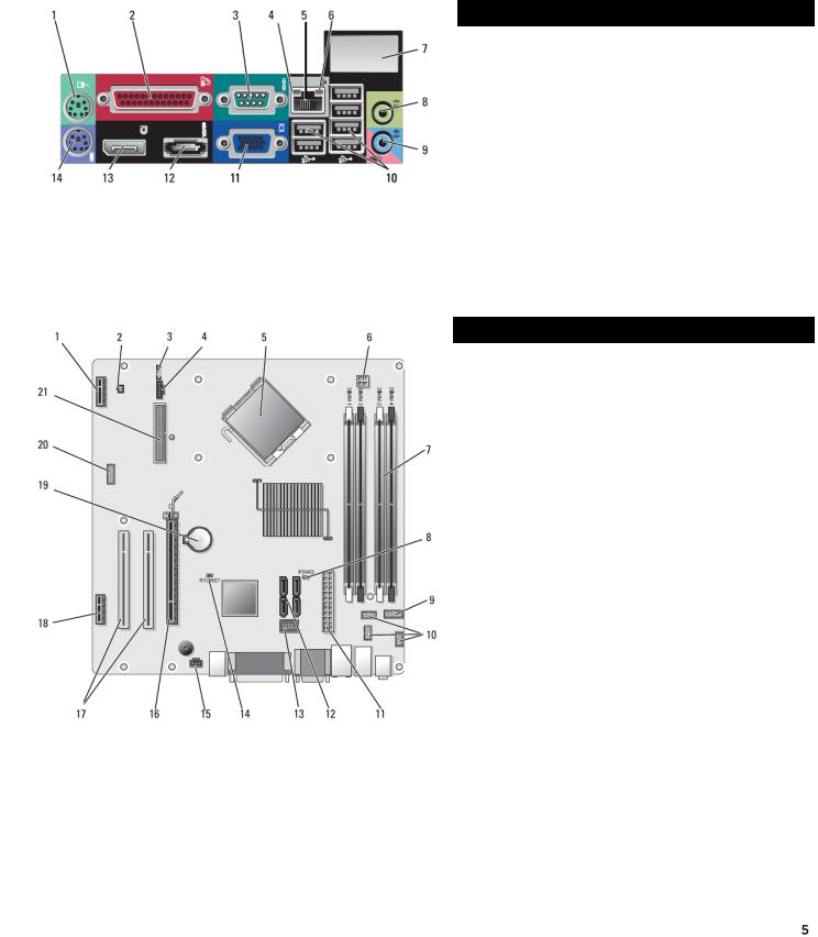
MINI TOWER COMPUTER (MT) VIEW (CONT.)
BACK PANEL CONNECTORS
1 |
PS/2 Mouse Connector |
8 |
Line-out Connector |
|
|
|
|
|
|
2 |
Parallel Connector |
9 |
Line-in/Microphone |
|
Connctor |
||||
|
|
|
||
|
|
|
|
|
3 |
Serial Connector |
10 |
USB 2.0 Connectors (6) |
|
|
|
|
|
|
4 |
Link Integrity Light |
11 |
VGA Connector |
|
|
|
|
|
|
5 |
Network Adapter |
12 |
eSATA Connector |
|
Connector |
||||
|
|
|
||
|
|
|
|
|
6 |
Network Activity Light |
13 |
DisplayPort Connector |
|
|
|
|
|
|
7 |
Wireless Network |
14 |
PS/2 Keyboard |
|
Adapter (optional) |
Connector |
|||
|
|
|||
|
|
|
|
SYSTEM BOARD
|
1 |
Wireless Card |
12 |
SATA Drive |
|
Connector |
Connectors (4) |
||
|
|
|
||
|
|
|
|
|
|
2 |
Thermal Sensor |
13 |
Internal USB Flex Bay |
|
Connector |
Connector |
||
|
|
|
||
|
|
|
|
|
|
3 |
Internal Speaker |
14 |
BIOS/RTC Reset |
|
Connector (INT SPKR1) |
Jumper Pins |
||
|
|
|
||
|
|
|
|
|
|
|
|
|
Intrusion Switch |
|
4 |
Fan (FAN_CPU) |
15 |
Connector |
|
|
|
|
(INTRUDER) |
|
|
|
|
|
|
5 |
Processor |
16 |
PCI Express x16 |
|
Connector (CPU) |
Connector (SLOT1) |
||
|
|
|
||
|
|
|
|
|
|
|
Processor Power |
|
PCI Connector |
|
6 |
Connector |
17 |
|
|
(SLOT2, SLOT3) |
|||
|
|
(12VPOWER) |
|
|
|
|
|
|
|
|
|
|
|
|
|
7 |
Memory Module |
18 |
PCIe x1 Connector |
|
Connectors (4) |
(SLOT4) |
||
|
|
|
||
|
|
|
|
|
|
8 |
Password Reset Pins |
19 |
RTC Battery |
|
(PSWD) |
|||
|
|
|
|
|
|
|
|
|
|
|
9 |
System Status LEDs |
20 |
Serial Connector |
|
Panel Connector |
|||
|
|
|
|
|
|
|
|
|
|
|
10 |
Front Panel |
21 |
Floppy Disk Connector |
|
Connectors (3) |
(DSKT2) |
||
|
|
|
|
|
|
11 |
Power Connector |
|
|
|
(POWER) |
|
|
|
|
|
|
|
|
|
|
|
|
|
DELL™ OPTIPLEX™ 960 TECHNICAL GUIDE
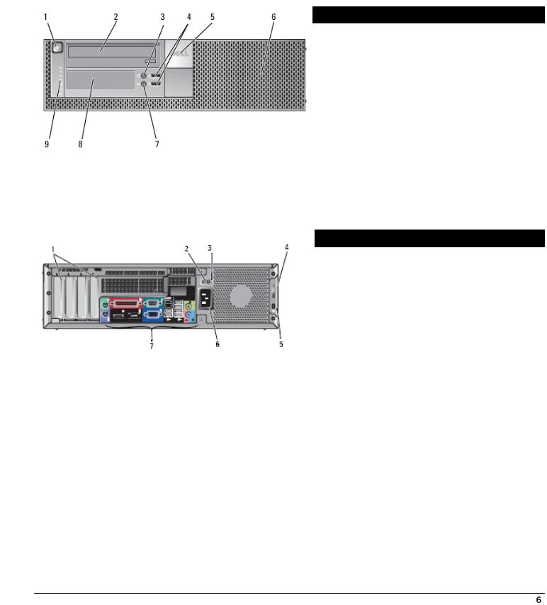
DESKTOP COMPUTER (DT) VIEW
FRONT VIEW
1 |
Power Button, |
6 |
Bezel |
|
Power Light |
||||
|
|
|
||
|
|
|
|
|
2 |
5.25” Drive Bay |
7 |
Microphone Connector |
|
|
|
|
|
|
3 |
Headphone Connector |
8 |
3.5” Drive Bay |
|
|
|
|
|
|
4 |
USB 2.0 Connectors (2) |
9 |
Diagnostic Lights |
|
|
|
|
|
|
5 |
Dell Badge |
|
|
|
|
|
|
|
BACK VIEW
1 |
Expansion |
5 |
Security Cable Slot |
|
card slots (4) |
||||
|
|
|
||
|
|
|
|
|
2 |
Power Supply Built in |
6 |
Power Connector |
|
Self Test Button |
||||
|
|
|
||
|
|
|
|
|
3 |
Power Supply Status |
7 |
Back-panel Connectors |
|
Light |
||||
|
|
|
||
|
|
|
|
|
|
Cover-release Latch |
|
|
|
4 |
and Padlock Ring |
|
|
|
(security screw |
|
|
||
|
|
|
||
|
optional) |
|
|
|
|
|
|
|

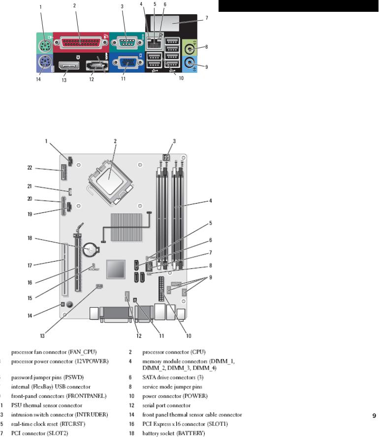
DELL™ OPTIPLEX™ 960 TECHNICAL GUIDE
DESKTOP COMPUTER (DT) VIEW (CONT.)
BACK PANEL CONNECTORS
|
1 |
PS/2 Mouse Connector |
8 |
Line-out Connector |
|
|
|
|
|
|
|
|
2 |
Parallel Connector |
9 |
Line-in/Microphone |
|
|
Connctor |
||||
|
|
|
|
|
|
|
|
|
|
|
|
|
3 |
Serial Connector |
10 |
USB 2.0 Connectors (6) |
|
|
|
|
|
|
|
|
4 |
Link Integrity Light |
11 |
VGA Connector |
|
|
|
|
|
|
|
|
5 |
Network Adapter |
12 |
eSATA Connector |
|
|
Connector |
||||
|
|
|
|
|
|
|
|
|
|
|
|
|
6 |
Network Activity Light |
13 |
DisplayPort Connector |
|
|
|
|
|
|
|
|
7 |
Wireless Network |
14 |
PS/2 Keyboard |
|
|
Adapter (optional) |
Connector |
|||
|
|
|
|
||
|
|
|
|
|
|
|
|
|
|
|
|
|
SYSTEM BOARD |
|
|
|
|
|
|
|
|
|
|
|
|
Fan Connector |
|
13 |
PCI Express x16 |
|
|
(FAN_CPU) |
|
Connector (SLOT1) |
|
|
|
|
|
||
|
|
|
|
|
|
|
|
Processor |
|
14 |
PCI Connector |
|
|
Connector (CPU) |
|
(SLOT2) |
|
|
|
|
|
||
|
|
|
|
|
|
|
|
Processor Power |
|
|
PCI Connector |
|
|
Connector |
|
15 |
|
|
|
|
(SLOT3) |
||
|
|
(12VPOWER) |
|
|
|
|
|
|
|
|
|
|
|
|
|
|
|
|
|
Memory Module |
|
|
|
|
|
Connectors (DIMM_1, |
|
16 |
PCI Express x1 |
|
|
DIMM_2, DIMM_3, |
|
Connector (SLOT4) |
|
|
|
|
|
||
|
|
DIMM_4) |
|
|
|
|
|
|
|
|
|
|
|
SATA Connectors (3) |
|
17 |
RTC Reset Jumper |
|
|
|
Pins |
||
|
|
|
|
|
|
|
|
|
|
|
|
|
|
Password Jumper |
|
18 |
Battery Socket |
|
|
(PSWD) |
|
(BATTERY) |
|
|
|
|
|
||
|
|
|
|
|
|
|
|
Internal USB Connector |
|
|
Riser Connector (uses |
|
|
|
19 |
PCI-E port/SLOT1 and |
|
|
|
(FLEX_USB) |
|
||
|
|
|
|
PCI port/SLOT2) |
|
|
|
|
|
|
|
|
|
|
|
|
|
|
|
Service Mode Jumper |
|
20 |
Floppy Connector |
|
|
(SERVICE_MODE) |
|
(DSKT) |
|
|
|
|
|
||
|
|
|
|
|
|
|
9 |
Power Connect |
|
21 |
Internal Speaker |
|
(POWER) |
|
(INT_SPKR) |
||
|
|
|
|
||
|
|
|
|
|
|
|
10 |
Front Panel Connector |
|
22 |
Connector for Optional |
|
(FRONTPANEL) |
|
Wireless Card |
||
|
|
|
|
|
|
|
11 |
Serial Connector |
|
23 |
Front Panel Thermal |
|
|
Sensor |
|||
|
|
|
|
|
|
|
|
|
|
|
|
|
12 |
Intrusion Switch |
|
|
|
|
Connector (INTRUDER) |
|
|
|
|
|
|
|
|
|
|
|
|
|
|
|
|

DELL™ OPTIPLEX™ 960 TECHNICAL GUIDE
SMALL FORM FACTOR COMPUTER (SFF) VIEW
VIEW
|
Power Button, |
6 |
Headphone Connector |
|
Power Light |
||
|
|
|
|
|
|
|
|
|
25” Drive Bay |
7 |
Microphone Connector |
|
|
|
|
|
5” Flex Bay for Floppy |
|
|
|
Drive (optional) or |
8 |
USB 2.0 Connectors (2) |
|
Media Card (optional) |
|
|
|
|
|
|
|
Badge |
9 |
Diagnostic Lights |
|
|
|
|
|
Bezel |
|
|
|
|
|
|
VIEW
|
Expansion card slots (2) |
5 |
Security Cable Slot |
|
|
|
|
|
Power Supply Check |
6 |
Power Cable Connector |
|
Button |
||
|
|
|
|
|
|
|
|
|
Power Supply Check |
7 |
Back-panel Connectors |
|
|
||
|
|
|
|
|
Cover-release Latch |
|
|
|
Padlock Ring |
|
|
|
(security screw |
|
|
|
optional) |
|
|
|
|
|
|
DELL™ OPTIPLEX™ 960 TECHNICAL GUIDE
SMALL FORM FACTOR COMPUTER (SFF) VIEW (CONT.)
BACK PANEL CONNECTORS
|
1 |
PS/2 Mouse Connector |
8 |
Line-out Connector |
|
|
|
|
|
|
|
|
2 |
Parallel Connector |
9 |
Line-in/Microphone |
|
|
Connctor |
||||
|
|
|
|
|
|
|
|
|
|
|
|
|
3 |
Serial Connector |
10 |
USB 2.0 Connectors (6) |
|
|
|
|
|
|
|
|
4 |
Link Integrity Light |
11 |
VGA Connector |
|
|
|
|
|
|
|
|
5 |
Network Adapter |
12 |
eSATA Connector |
|
|
Connector |
||||
|
|
|
|
|
|
|
|
|
|
|
|
|
6 |
Network Activity Light |
13 |
DisplayPort Connector |
|
|
|
|
|
|
|
|
7 |
Wireless Network |
14 |
PS/2 Keyboard |
|
|
Adapter (optional) |
Connector |
|||
|
|
|
|
||
|
|
|
|
|
|
|
|
|
|
|
|
|
|
|
|
|
|
|
|
|
|
12 |
Serial Port Connector |
|
|
|
|
|
|
|
|
Connector |
|
|
Intrusion Switch |
|
|
|
13 |
Connector |
|
|
|
|
|
||
|
|
|
|
|
(INTRUDER) |
|
|
|
|
|
|
|
|
Power |
|
|
Front Panel Thermal |
|
|
|
|
14 |
Sensor Cable |
|
|
|
|
|
Connector |
|
|
|
|
|
|
|
|
Module |
|
|
|
|
|
(DIMM_1, |
|
15 |
Real Time Clock Reset |
|
|
DIMM_3, |
|
(RTCRST) |
|
|
|
|
|
||
|
|
|
|
|
|
|
|
Jumper Pins |
|
16 |
PCI Express x16 |
|
|
|
|
Connector (SLOT1) |
|
|
|
|
|
|
|
|
|
|
|
|
|
|
|
|
|
17 |
PCI Connector |
|
|
(3) |
|
(SLOT2) |
|
|
|
|
|
||
|
|
|
|
|
|
|
|
(FlexBay) |
|
18 |
Battery Socket |
|
|
|
|
(BATTERY) |
|
|
|
|
|
|
|
|
|
|
|
|
|
|
|
|
|
19 |
Hard Drive Fan |
|
|
|
|
Connector (FAN_HDD) |
|
|
|
|
|
|
|
|
|
|
|
|
|
|
|
Connector |
|
20 |
Floppy Drive |
|
|
|
|
Connector (DSKT) |
|
|
|
|
|
|
|
|
|
|
|
|
|
|
|
|
|
21 |
Internal Speaker |
|
|
|
|
|
|
|
|
Sensor |
|
22 |
Connector for Optional |
|
|
|
|
Wireless Card |
|
|
|
|
|
|
|
|
|
|
|
|
|
|
|
|
|
|
|

DELL™ OPTIPLEX™ 960 TECHNICAL GUIDE
MARKETING SYSTEM CONFIGURATIONS
NO TE : Of feri ng s m a y v ar y b y regi on . Fo r m ore i nf orm ati on r ega rdi ng t he c onfi gura ti on o f yo ur com puter, cl i ck S tar t>H el p and S uppor t a nd sel ec t th e opti on to vi ew i nform ati on abou t you r com pute r .
OPERATING SYSTEM
NO TE : One of t he fol l ow i ng Opera ti ng S ys tem s w i l l be prei ns tal l ed .
|
MT |
|
DT |
|
SFF |
|
|
|
|
|
|||
Windows Vista® operating system |
Windows Vista® SP1 Business (32 and 64 bit), |
|||||
Windows Vista® SP1 Ultimate (32 bit), |
||||||
|
||||||
Windows XP® operating system |
Windows® XP Professional SP3 via Windows® |
|||||
Vista Business Downgrade Rights (32 bit) |
||||||
|
||||||
Other |
|
FreeDOS for (n-series), |
|
|||
|
|
|
|
|
||
OS Media Support |
X |
|
X |
|
X |
|
|
|
|
|
|
|
|
CHIPSET |
|
|
|
|
|
|
|
|
|
|
|
||
|
MT |
|
DT |
|
SFF |
|
|
|
|
|
|||
Chipset |
Intel Q45 Express Chipset w/ICH10DO |
|||||
|
|
|
|
|
|
|
Non-volatile memory on chipset |
|
|
|
|
|
|
|
|
|||||
BIOS Configuration SPI (Serial Peripheral Interface) |
64Mbit (8MB) located at SPI_FLASH on chipset |
|||||
|
|
|||||
TPM 1.2 Security Device (Trusted Platform Module)1 |
16KB located at TPM1P2 on chipset |
|||||
NIC EEPROM |
LOM configuration contained within SPI_FLASH – |
|||||
|
no dedicated LOM EEPROM |
|
||||
|
|
|
||||
|
|
|
|
|
|
|
DELL™ OPTIPLEX™ 960 TECHNICAL GUIDE
PROCESSOR
NO TE : Gl obal S t andard P roduct s ( GS P ) ar e |
a s ubset of |
Del l ' s |
rel ati on s hi p produc ts tha t a re |
m anaged for |
avai l abi l i t y and s yn chro n i z ed transi ti ons on a |
w orl dw i de basi s . The y ensu r e the s am e pl at form i s avai l abl e f or |
|||
purcha se gl obal l y. Thi s al l ow s custom er s to |
r ed uce th e |
num ber |
of c onfi gurati on s m anage d on |
a w orl dw i de |
basi s, t her eb y r educi ng t hei r cos ts . Th e y al so en a bl e com pani e s to i m pl em ent gl obal I T s tan dard s b y l o cki ng i n speci fi c prod uct con fi gu rati on s w orl dw i de . The fol l ow i ng GS P proces s ors i den ti fi ed bel ow w i ll be m ade avai l abl e to D el l cus tom e rs .
NO TE : P roces sor num ber s are no t a m ea sur e of pe rform an ce .
|
|
MT |
DT |
SFF |
|
|
|
|
|
Intel Quad Core processors |
|
|
|
|
|
|
|
|
|
Intel Core 2 Quad Q9650/3.00GHz,12M,1333FSB |
X-GSP |
X-GSP |
X-GSP |
|
|
|
|
|
|
Intel Core 2 Quad Q9550/2.83GHz,12M,1333FSB |
X-GSP |
X-GSP |
X-GSP |
|
|
|
|
|
|
Intel Core 2 Quad Q9450/2.66GHz, 12M, 1333FSB |
X |
X |
X |
|
|
|
|
|
|
Intel Core 2 Quad Q9400/2.66GHz,6M,1333FSB |
X |
X |
X |
|
|
|
|
|
|
Intel Dual Core processors |
|
|
|
|
|
|
|
|
|
Intel Core 2 |
Duo E8600/3.33GHz, 6M, 1333FSB |
X-GSP |
X-GSP |
X-GSP |
|
|
|
|
|
Intel Core 2 |
Duo E8500/3.16GHz,6M,1333FSB |
X-GSP |
X-GSP |
X-GSP |
|
|
|
|
|
Intel Core 2 |
Duo E8400/3.0GHz,6M,1333FSB |
X-GSP |
X-GSP |
X-GSP |
|
|
|
|
|
Intel Core 2 |
Duo E8300/2.83GHz, 6M,1333FSB |
X |
X |
X |
|
|
|
|
|

DELL™ OPTIPLEX™ 960 TECHNICAL GUIDE
ADVANCED SYSTEM MANA GEABILITY MODES
NO TE : Hardw ar e m anag e m ent m ode op ti ons al l ow you to sel ec t th e ri gh t s ys t em s m anag em en t f ea t ure supp ort for you r en terp ri se . Del l ’ s i nnova ti ve appro ach to scal abl e r em ote cl i ent m anagem en t of fer s you a choi c e of bui l t - i n hardw ar e m anag e m ent cap abi l i ti e s ac ross pl atfo rm off eri ngs .
Th e l ate st g ener ati on o f I ntel ® vP ro™ t echnol og y pr ovi de s the capabi l i t y t o m anage yo ur i ns ta l l base of s ys tem s r ega rdl es s of th e pow er sta te o r hardw ar e func ti onal i t y of the s ys tem .
Thi s func ti onal i t y al l ow s I T to addre ss m an y i ssu e s rem ot el y ra the r th an ha vi ng to ph ys i cal l y vi si t s ys t em s . Th e Opti P l e x 96 0 suppor t s the l a te st g ener ati on o f I ntel ® vP ro™ tec hnol og y.
I ntel ® i AM T te chnol og y/ I ntel ® vP r o™ te chnol og y s upport t he fol l ow i ng fe at ures:
As s et repo rti ng and i n ve ntor y ca pabi l i ti e s, R em ot e t roubl esho oti ng and r e pai r, Cl i en t S ys t em I sol a t i on, Rem ot e patchi ng/ upd ati ng
I ntel ® vP ro™ te chnol og y adds th es e addi ti on al fe a ture s: |
|
|
|
|
|
|
Cl i ent i ni ti al ed “ Fa st C al l for Hel p” / be yo nd fi rew al l s ys tem s |
m an agem en t capabi l i t y, |
M i crosof t N AP |
support, |
|||
Hard ened s ecu ri t y m oni to ri ng, S upport fo r the l at e st gen era ti on of I n tel ® C ore™ 2 Qu ad P roce sso rs |
|
|||||
* T h e f u n c t i o n a l i t y d e s c r i b e d a b o v e r e q u i r e s a n a p p r o p r i a t e s o f t wa r e m a n a g e m e n t c o n s o l e |
|
|
|
|||
|
|
|
|
|
|
|
|
|
MT |
|
DT |
|
SFF |
|
|
|
|
|
|
|
Intel vPro Advanced Client Systems Management* (iAMT Professional 5.0) |
|
X |
|
X |
|
X |
|
|
|
|
|
|
|
Intel Standard Manageability* (iAMT 5.0) |
|
X |
|
X |
|
X |
|
|
|
|
|
|
|
No ManagementUpgradeable |
|
X |
|
X |
|
X |
|
|
|
|
|
|
|
Management DisabledNot Upgradeable |
|
X |
|
X |
|
X |
|
|
|
|
|
|
|
* This functionality requires the appropriate software management console
MEMORY
Your com put er suppo rt s a m axi m um of 8GB of m em or y w hen you use f our 2GB DI M M s; how eve r, 32 - bi t opera ti ng s ys t em s, such as th e 32 - bi t v ersi on o f M i crosoft ® W i ndow s ® X P , can onl y u se a m axi m um of 4GB of addre ss spa ce . M oreove r , cer tai n com ponent s w i t hi n the com pute r r equi re addre ss spa ce i n the 4G B rang e . An y add re ss sp ac e re se rved for thes e com pon e nts c anno t be us ed b y com puter m em or y; the re fore, the am ount of m em or y av ai l a bl e to th e oper ati ng s ys t em i s l ess than 4 GB .
NO TE : The enti r e 8G B m e m or y range i s av ai l abl e t o 64 - bi t oper ati ng s ys tem s .
M em or y m odul e s shoul d be i nstal l ed i n pai rs of m atch ed m em or y si z e, spe ed, and technol og y. I f th e m em or y m odul es ar e no t i ns tal l ed i n m atch ed pai rs, t he co m puter w i l l conti nu e to o pera te, bu t w i th a sl i ght r educti on i n perform an ce .
|
|
MT |
DT |
SFF |
|
|
|
|
|
Type: DDR2 Synch DRAM Non-ECC Memory |
|
800MHz |
|
|
|
|
|
|
|
DIMM Slots |
4 |
4 |
4 |
|
|
|
|
|
|
DIMM Capacities |
Up to 8GB |
Up to 8GB |
Up to 8GB |
|
|
|
|
|
|
Minimum Memory |
1GB |
1GB |
1GB |
|
|
|
|
|
|
Maximum Memory with 800MHz speed memory |
8GB1 |
8GB1 |
8GB1 |
|
800MHz Memory configurations |
|
|
|
|
|
|
|
|
|
8GB1 |
DDR2 Non-ECC SDRAM, 800MHz, (4 DIMM) |
X |
X |
X |
8GB1 |
DDR2 Non-ECC SDRAM, 800MHz, (2 DIMM) |
X |
X |
X |
4GB1 |
DDR2 Non-ECC SDRAM, 800MHz, (4 DIMM) |
X |
X |
X |
4GB1 |
DDR2 Non-ECC SDRAM, 800MHz, (2 DIMM) |
X |
X |
X |
3GB DDR2 Non-ECC SDRAM, 800MHz, (4 DIMM) |
X |
X |
X |
|
|
|
|
|
|
3GB DDR2 Non-ECC SDRAM, 800MHz, (2 DIMM) |
X |
X |
X |
|
|
|
|
|
|
 Loading...