


Dell™ OptiPlex™ 780 Ultra Small Form Factor—Service
Manual
Working on Your Computer
Removing and Replacing Parts
Specifications
System Board Layout
System Setup
Diagnostics
Notes, Cautions, and Warnings
NOTE: A NOTE indicates important information that helps you make better use of your computer.
CAUTION: A CAUTION indicates potential damage to hardware or loss of data if instructions are not followed.
WARNING: A WARNING indicates a potential for property damage, personal injury, or death.
If you purchased a Dell™ n Series computer, any references in this document to Microsoft® Windows® operating systems are not applicable.
Information in this document is subject to change without notice. © 2010 Dell Inc. All rights reserved.
Reproduction of this material in any manner whatsoever without the written permission of Dell Inc. is strictly forbidden.
Trademarks used in this text: Dell, the DELL logo, and OptiPlex are trademarks of Dell Inc.; ATI Radeon is a trademarks of
Advanced Micro Devices, Inc; Intel, Pentium, Celeron, and Core are either trademarks or registered trademarks of Intel Corporation; Blu-ray Disc is a trademark of the Blu-ray Disc Association; Microsoft, Windows, Windows Vista, and the Windows Vista start button are either trademarks or registered trademarks of Microsoft Corporation in the United States and/or other countries.
Other trademarks and trade names may be used in this document to refer to either the entities claiming the marks and names or their products. Dell Inc. disclaims any proprietary interest in trademarks and trade names other than its own.
October 2012 |
Rev. A01 |

Back to Contents Page
Working on Your Computer
Dell™ OptiPlex™ 780 Ultra Small Form Factor—Service Manual
 Before Working Inside Your Computer
 Recommended Tools
 Turning Off Your Computer
 After Working Inside Your Computer
Before Working Inside Your Computer
Use the following safety guidelines to help protect your computer from potential damage and to help to ensure your personal safety. Unless otherwise noted, each procedure included in this document assumes that the following conditions exist:
 You have performed the steps in Working on Your Computer.
 You have read the safety information that shipped with your computer.
 A component can be replaced or—if purchased separately—installed by performing the removal procedure in reverse order.
WARNING: Before working inside your computer, read the safety information that shipped with your computer. For additional safety best practices information, see the Regulatory Compliance Homepage at www.dell.com/regulatory_compliance.
CAUTION: Only a certified service technician should perform repairs on your computer. Damage due to servicing that is not authorized by Dell is not covered by your warranty.
CAUTION: To avoid electrostatic discharge, ground yourself by using a wrist grounding strap or by periodically touching an unpainted metal surface, such as a connector on the back of the computer.
CAUTION: Handle components and cards with care. Do not touch the components or contacts on a card. Hold a card by its edges or by its metal mounting bracket. Hold a component such as a processor by its edges, not by its pins.
CAUTION: When you disconnect a cable, pull on its connector or on its pull-tab, not on the cable itself. Some cables have connectors with locking tabs; if you are disconnecting this type of cable, press in on the locking tabs before you disconnect the cable. As you pull connectors apart, keep them evenly aligned to avoid bending any connector pins. Also, before you connect a cable, ensure that both connectors are correctly oriented and aligned.
NOTE: The color of your computer and certain components may appear differently than shown in this document.
To avoid damaging your computer, perform the following steps before you begin working inside the computer.
1.Ensure that your work surface is flat and clean to prevent the cover from being scratched.
2.Turn off your computer (see Turning Off Your Computer).
CAUTION: To disconnect a network cable, first unplug the cable from your computer and then unplug the cable from the network device.
3.Disconnect all network cables from the computer.
4.Disconnect your computer and all attached devices from their electrical outlets.
5.Press and hold the power button while the computer is unplugged to ground the system board.
6.Remove the cover (see Removing the cover).
CAUTION: Before touching anything inside your computer, ground yourself by touching an unpainted metal surface, such as the metal at the back of the computer. While you work, periodically touch an unpainted metal surface to dissipate static electricity, which could harm internal components.
Recommended Tools
The procedures in this document may require the following tools:

Small flat-blade screwdriver
Phillips screwdriver
Small plastic scribe
Flash BIOS update program media
Turning Off Your Computer
CAUTION: To avoid losing data, save and close all open files and exit all open programs before you turn off your computer.
1. Shut down the operating system:
 In Windows Vista®:
Click Start  , then click the arrow in the lower-right corner of the Start menu as shown below, and then click Shut Down.
 In Windows® XP:
Click Start® Turn Off Computer® Turn Off.
The computer turns off after the operating system shutdown process is complete.
2.Ensure that the computer and all attached devices are turned off. If your computer and attached devices did not automatically turn off when you shut down your operating system, press and hold the power button for about 6 seconds to turn them off.
After Working Inside Your Computer
After you complete any replacement procedure, ensure you connect any external devices, cards, and cables before turning on your computer.
1. Replace the cover (see Removing the Cover).
CAUTION: To connect a network cable, first plug the cable into the network device and then plug it into the computer.
2.Connect any telephone or network cables to your computer.
3.Connect your computer and all attached devices to their electrical outlets.
4.Turn on your computer.
5.Verify that the computer works correctly by running the Dell Diagnostics. See Dell Diagnostics.
Back to Contents Page

Back to Contents Page
Removing and Replacing Parts
Dell™ OptiPlex™ 780 Ultra Small Form Factor—Service Manual
 Cover
Cover
 Drive Cage
 Optical Drive
 Wireless Local Area Network (WLAN)
Card
 System Fan
 Heat Sink and Processor
 Intrusion Switch
 Coin-Cell Battery
 System Board
 Front Bezel
 Hard Drive
 Control Panel
 Internal Antenna Cable
 Internal Speaker
 Memory
 I/O Board
 Power Supply
Back to Contents Page
Back to Contents Page
Specifications
Dell™ OptiPlex™ 780 Ultra Small Form Factor—Service Manual
NOTE: Offerings may vary by region. For more information regarding the configuration of your computer, click Start→ Help and Support and select the option to view information about your computer.
Processor |
|
Type |
Intel® Core™ 2 Duo, Intel Pentium® |
|
Dual-Core, |
|
Intel Celeron® Dual-Core, Intel Celeron |
Level 2 (L2) cache |
512 KB to 6 MB |
Memory |
|
Type |
DDR3 SDRAM (non-ECC memory only) |
Speed |
1066 MHz |
Connectors |
two |
Capacity |
1 GB or 2 GB |
Minimum memory |
1 GB |
Maximum memory |
4 GB |
Video |
|
Integrated |
Intel Q45 graphics controller |
Audio |
|
Integrated |
ADI 1984A High Definition Audio Codec |
Network |
|
Integrated |
Intel 82567 Gigabit 1 LAN 10/100/1000 |
|
Mbps |
System Information |
|
Chipset |
Intel Q45 Express chipset with ICH10DO |
DMA channels |
8 |
Interrupt levels |
24 |
BIOS chip (NVRAM) |
64 Mb (8 MB) |
Expansion Bus |
|
Bus type |
SATA 1.0A and 2.0 |
|
USB 2.0 |
Bus speed |
SATA: 1.5 Gbps and 3.0 Gbps |
|
USB: 480 Mbps |
Cards |
|
PCI |
not available |
PCI Express x1 |
not available |
PCI Express x16 |
not available |

Drives |
|
Externally accessible |
|
slimline drive bays |
one bay for SATA DVD-ROM / DVD+/– |
|
RW |
Internally accessible |
|
2.5-inch drive bays |
one |
External Connectors |
|
Audio |
|
back panel |
two connectors: line-out (headphone) |
|
and line-in (microphone) |
front panel |
two connectors: line-out (headphone) |
|
and line-in (microphone) |
Network |
one RJ45 connector |
Serial |
one 9-pin connector; 16550C compatible |
USB |
|
front panel |
two |
back panel |
five |
eSATA |
one |
Video |
15-pin VGA connector |
|
20-pin DisplayPort™ connector |
|
NOTE: Available video connectors may |
|
vary based on the graphics card |
|
selected. |
System Board Connectors |
|
Serial ATA |
two 7-pin connectors |
Memory |
four 240-pin connectors |
Internal USB device |
one 10-pin connector (supports two USB |
|
ports) |
Processor fan |
one 4-pin connector |
System fan |
one 3-pin connector |
Front panel control |
one 9-pin connector |
Front panel audio |
one 10-pin connector |
Processor |
one socket N |
Power 12 V |
one 4-pin connector |
Power |
one 24-pin connector |
Power |
|
Wattage |
180 W |
Maximum heat dissipation (MHD) |
750 BTU/hr |
Voltage |
90–264 VAC, 47–63 Hz, 2.6 A |
Coin-cell battery |
3 V CR2032 lithium coin cell |
 NOTE: Heat dissipation is calculated by using the power supply wattage rating.
NOTE: See the safety information that shipped with your computer for important voltage setting information
 Physical
Height |
23.7 cm (9.3 inches) |
Width |
6.5 cm (2.6 inches) |
Depth |
24.0 cm (9.4 inches) |
Weight |
3.2 kg (7 lb) |
Environmental |
|
 Temperature
Operating
Storage
 Relative humidity (noncondensing)
Maximum vibration Operating
Storage
 Maximum shock
Operating
 10 °C to 35 °C (50 °F to 95 °F)
–40 °C to 65 °C (–40 °F to 149 °F)
operating: 20% to 80% storage: 5% to 95%
 5–350 Hz at 0.0002 G2/Hz 5–500 Hz at 0.001 to 0.01 G2/Hz
40 G +/– 5% with pulse duration of 2 msec +/– 10% (equivalent to 20 in/sec [51 cm/sec])
Storage |
105 G +/– 5% with pulse duration of 2 |
|
msec +/– 10% (equivalent to 50 in/sec |
|
[127 cm/sec]) |
Altitude |
|
Operating |
–15.2 m to 3048 m (–50 ft to 10,000 ft) |
Storage |
–15.2 m to 10,668 m (–50 ft to 35,000 |
|
ft) |
Airborne contaminant level |
G2 or lower as defined by ISA- |
|
S71.04-1985 |
|
|
Back to Contents Page |
|

Back to Contents Page
System Board Layout
Dell™ OptiPlex™ 780 Ultra Small Form Factor—Service Manual
WARNING: Before working inside your computer, read the safety information that shipped with your computer. For additional safety best practices information, see the Regulatory Compliance Homepage at www.dell.com/regulatory_compliance.
1 |
intrusion switch connector (INTRUDER) |
2 |
power connector (POWER) |
3 |
processor connector (CPU) |
4 |
front-panel connector (FRONTPANEL) |
5 |
memory module connectors (DIMM_1, DIMM_2) |
6 |
internal speaker connector |
7 |
front-panel connector (FRONTPANEL) |
8 |
front-fan connectors (FAN_FRONT) |
9 |
PCI-E mini card (PCIE_MINICARD) |
10 |
fan connectors (FAN_CPU) |
11 |
power connector (POWER) |
12 |
SATA drive connectors (SATA0, SATA1) |
13 |
hard-drive or optical-drive power connector (HDD_ODD_POWER) |
14 |
battery socket (BATTERY) |
Back to Contents Page

Back to Contents Page
System Setup
Dell™ OptiPlex™ 760 Ultra Small Form Factor—Service Manual
Overview |
Entering System Setup |
System Setup Options |
Boot Sequence |
Booting to a USB Device |
Booting to a USB Device |
Password Protection |
Jumper Settings |
Clearing Forgotten Passwords |
Clearing CMOS Settings |
Overview
Use System Setup to:
 Change the system configuration information after you add, change, or remove any hardware in your computer
 Set or change a user-selectable option such as the user password
Read the current amount of memory or set the type of hard drive installed
Before you use System Setup, it is recommended that you write down the System Setup screen information for future reference.
CAUTION: Unless you are an expert computer user, do not change the settings for this program. Certain changes can make your computer work incorrectly.
Entering System Setup
1.Turn on (or restart) your computer.
2.When the DELL™ logo is displayed, watch for the F12 prompt to appear.
3.Press <F12> immediately. The Boot Menu appears.
4.Use the up and down arrow keys to select System Setup and then press <Enter>.
NOTE: The F12 prompt indicates that the keyboard has initialized. This prompt can appear very quickly, so you must watch for it to display, and then press <F12>. If you press <F12> before you are prompted, this keystroke will be lost.
5.If you wait too long and the operating system logo appears, continue to wait until you see the Microsoft® Windows® desktop. Then, shut down your computer and try again.
System Setup Screen
The System Setup screen displays current or changeable configuration information for your computer. Information on the screen is divided into two areas: the menu, and the main window.
Options List — This field appears on the left side of the system setup window. The field is a scrollable list containing features that define the configuration of your computer, including installed hardware, power conservation, and security features.
Option Field — This field contains information about each option. In this field you can view your current settings and make changes to your settings.
Use the Tab and Up/Down arrow keys on your keyboard to navigate or click to navigate using the mouse.
System Setup Options
NOTE: Depending on your computer and installed devices, the items listed in this section may not appear, or may not appear exactly as listed.
WARNING: eSATA is designed to function only if the SATA Operation mode in system Setup (BIOS) is set to either IRRT or AHCI. If it is set to ATA, the eSATA functionality is lost though the connector can still be used as a USB port.
General
System
Board
Displays the following information:
System information: Displays BIOS Info, System Info, and the Service Tag.
 Memory information: Displays Installed Memory, Usable Memory, Memory Speed, Memory Channel Mode, and Memory Technology.
 Processor information: Displays the Processor Type, Processor Speed, Processor Bus Speed,
Processor L2 cache, Processor ID.
PCI information: Displays available slots on the system board.
Date/Time
Boot
Sequence
 Displays the system date and time. Changes to the system date and time take effect immediately.
Specifies the order in which the computer attempts to find an operating system from the devices specified in this list.
Drives
Diskette drive
SATA Operation
S.M.A.R.T.
Reporting
 Drives
Identifies and defines the floppy drive attached to the FLOPPY connector on the system board as:
 Disable
 USB
USB
Internal (default)
 Read Only
Configures the operating mode of the integrated hard drive controller to:
AHCI (default)
 ATA
ATA
 Legacy
Enables or disables integrated drive errors to be reported during system startup. This option is disabled by default.
 Enables or disables the SATA or ATA drives connected to the system board.
System Configuration
Integrated NIC
USB Controller
Enables or disables the integrated network card. You can set the integrated NIC to:
Enable (default)
 Disable
 Enable with PXE
 Enable with ImageSever
Enables or disables the integrated USB controller. You can set the USB controller to:
Enable (default)
 Disable
 No boot
Parallel Port |
Identifies and defines the parallel port settings. You can set the parallel port to: |
Parallel Port
Address
Serial Port #1
Miscellaneous
Devices
 Disable
 AT
AT
 PS/2 (default)
 EPP
EPP
 ECP No DMA
 ECP DMA 1
 ECP DMA 3
 Sets the base I/O address of the integrated parallel port.
Identifies and defines the serial port settings. You can set the serial port to:
 Disable
Auto (default)
 COM1
COM1
 COM3
COM3
NOTE: Auto, the default setting, automatically configures a connector to a particular designation (COM1 or COM3).
Enables or disables the following onboard devices:
 Front USB
 Rear Dual USB
 Rear Quad USB
 PCI slots
 Audio
Audio
 Video
Video
Primary Video Specifies which video controller is primary when two video controllers are present on the computer.
Auto (default)
 Onboard/PEG
Performance
Multi Core Support
Intel® SpeedStep™
Limit CPUID Value
HDD Acoustic Mode
Specifies whether one or all the cores of the processor will be enabled.
NOTE: The performance of some applications improve with additional cores. Enables or disables the Intel SpeedStep mode.
This option is disabled by default. Enables or disables the CPUID limit. This option is disabled by default.
Sets the performance speed and noise level of your hard drive to:
Bypass (default)
 Quiet
Quiet
 Suggested
 Performance
 Virtualization Support
VT for |
Enables or disables the Virtual Machine Monitor (VMM) from utilizing the additional hardware capabilities |
Direct I/O |
provided by Intel Virtualization technology for direct I/O. |
Security
Administrative
Password
System
Password
Provides restricted access to the computer's system setup program in the same way that access to the system can be restricted with the System Password option.
This option is not set by default.
 Displays the current status of the system's password security feature and allows a new system

Password
Changes
TPM Security
CPU XD
Support
Computrace(R)
password to be assigned and verified.
This option is not set by default.
Enables or disables the user from changing the system password without the administrative password.
This option is enabled by default.
Enables or disables the trusted platform module (TPM) security.
You can set the TPM security to:
 Deactivate (default)
 Activate
 Clear
Clear
NOTE: When TPM Security is set to Clear the system setup program clears the user information stored in the TPM.
Enables or disables the execute disable mode of the processor. This option is enabled by default.
Enables or disables the optional Computrace® service designed for asset management. You can set this option to:
 Deactivate (default)
 Disable
 Activate
SATA-0
Password
Displays the current status of the password set for the hard drive connected to the SATA-0 connector on the system board.
You can also set a new password. This option is not set by default.
NOTE: The system setup program displays a password for each of the hard drives connected to your system board.
Power Management
AC Recovery
Auto On Time
Low Power
Mode
Remote
Wakeup
 Suspend Mode
Determines how the system responds when AC power is re-applied after a power loss. You can set the AC Recovery to:
Power Off (default)
 Power On
 Last State
Sets time to automatically turn on the computer.
Time is kept in the standard 12-hour format (hours:minutes:seconds).
Change the startup time by typing the values in the time and AM/PM fields.
NOTE: This feature does not work if you turn off your computer using the switch on a power strip or surge protector or if Auto Power On is set to disabled.
Enables or disables low power mode. This option is disabled by default.
NOTE: When low power mode is enabled, the integrated network card is disabled.
Allows the system to power up when a network interface controller receives a wake up signal. You can set Remote Wakeup to:
Disable (default)
 Enable
 Enable with Boot NIC

Fan Control
Override
 Maintenance
Sets the power management suspend mode to:
 S1
S1
S3 (default)
NOTE: If the AMT Management Engine (ME) of the system is disabled, the S1 suspend mode is unavailable in the system setup.
Controls the speed of the system fan.
NOTE: When enabled, the fan runs at full speed.
 Service Tag
Asset Tag
SERR Messages
Image Server
Lookup Method
 Displays the Service Tag of your computer.
  Allows you to create a system asset tag if an asset tag is not already set. This option is not set by default.
Controls the SERR Message mechanism. This option is enabled by default.
Some graphics cards require the SERR Message mechanism be disabled.
Specifies how the ImageServer looksup the server address.
ImageServer IP
ImageServer Port
Client DHCP
Client IP
 Static IP
 DNS
DNS
NOTE: You must set the Integrated NIC to Enable with ImageServer to set the Lookup Method.
Specifies the primary static IP address of the ImageServer with which the client software communicates.
The default IP address is 255.255.255.255
NOTE: You must set the Integrated NIC to Enable with ImageServer to set the ImageServer IP.
Specifies the primary IP port of the image server with which the client software communicates. The default IP port is 06910.
Specifies how the client obtains the IP address.
 Static IP
DHCP (default)
Specifies the static IP address of the client.
The default IP address is 255.255.255.255
Client
SubnetMask
Client Gateway
 License Status
NOTE: To set Client IP you must set Client DHCP to Static IP
Specifies the subnet mask for the client. The default setting is 255.255.255.255
NOTE: To set Client SubnetMask you must set Client DHCP to Static IP
Specifies the gateway IP address for the client.
The default setting is 255.255.255.255
NOTE: To set Client SubnetMask you must set Client DHCP to Static IP
 Displays the current license status.

Post Behavior
Fast
Boot
NumLock
LED
POST
Hotkeys
 When enabled (default), your computer starts more quickly because it skips certain configurations and tests.
  Enables or disables the NumLock feature when your computer starts.
When enabled (default), this option activates the numeric and mathematical features shown at the top of each key. When disabled, this option activates the cursor-control functions labeled on the bottom of each key
Allows you to specify the function keys to display on the screen when the computer starts.
Enable F2 = Setup (enabled by default)
 Enable F12 = Boot menu (enabled by default)
Keyboard Enables or disables keyboard error reporting when the computer starts.
Errors
This option is enabled by default.
System Logs
BIOS Events Displays the system event log and allows you to:
 Clear Log
 Mark all Entries
Boot Sequence
This feature allows you to change the Boot Device Property for devices.
Option Settings
Onboard USB Floppy Drive — The computer attempts to boot from the floppy drive.
Onboard SATA Hard Drive — The computer attempts to boot from the hard drive.
USB Device — The computer attempts to boot from a removable device, such as a USB key.
CD/DVD — The computer attempts to boot from the disc drive.
Changing the Boot Sequence for the Current Boot
You can use this feature, for example, to restart your computer to a USB device, such as a floppy drive, memory key, or optical drive.
1.If you are booting to a USB device, connect the USB device to a USB connector.
2.Turn on (or restart) your computer.
3. When F12 = Boot Menu appears in the upper-right corner of the screen, press <F12>.
If you wait too long and the operating system logo appears, continue to wait until you see the Microsoft Windows desktop, then shut down your computer and try again.
4.The Boot Menu appears, listing all available boot devices.
5.Use the arrow keys to select the appropriate device (for the current boot only).
NOTE: To boot to a USB device, the device must be bootable. To ensure that a device is bootable, check the device documentation.

Changing the Boot Sequence for Future Boots
1.Enter System Setup (see Entering System Setup).
2.Click to expand SystemBoard and then click Boot Sequence.
3.Highlight the appropriate device from the list of devices on the right and then click the up or down arrows to move the item you want to change.
4.Click Apply to save the changes and then click Exit to exit System Setup and resume the boot process.
Booting to a USB Device
NOTE: To boot to a USB device, the device must be bootable. To ensure that your device is bootable, check the device documentation.
Memory Key
1.Insert the memory key into a USB port and restart the computer.
2.When F12 = Boot Menu appears in the upper-right corner of the screen, press <F12>.
The BIOS detects the device and adds the USB device option to the boot menu. 3. From the boot menu, select the number that appears next to the USB device.
The computer boots to the USB device.
Floppy Drive
1.In system setup, set the Diskette Drive option to USB.
2.Save and exit system setup.
3.Connect the USB floppy drive, insert a bootable floppy, and re-boot the computer.
Password Protection
CAUTION: Although passwords provide security for the data on your computer, they are not foolproof. If your data requires more security, it is your responsibility to obtain and use additional forms of protection, such as data encryption programs.
System Password
CAUTION: If you leave your computer running and unattended without having a system password assigned, or if you leave your computer unlocked so that someone can disable the password by changing a jumper setting, anyone can access the data stored on your hard drive.
Option Settings
You cannot change or enter a new system password if either of the following two options is displayed:
 Set — A system password is assigned.
 Disabled — The system password is disabled by a jumper setting on the system board.

You can only assign a system password when the following option is displayed:
Not Set — No system password is assigned and the password jumper on the system board is in the enabled position (the default setting).
Assigning a System Password
To exit without assigning a system password, press <Esc> at any time (before you press the OK button in step 4).
1.Enter system setup (see Entering System Setup).
2.Select System Password, and verify that Password Status is set to Not Set.
3.Type your new system password.
You can use up to 32 characters. To erase a character when entering your password, press <Backspace>. The password is case sensitive.
Certain key combinations are not valid. If you enter one of these invalid combinations, the speaker emits a beep.
As you press each character key (or the spacebar for a blank space), a placeholder appears.
4. Type your new password a second time to confirm and press OK button.
The password setting changes to Set.
Typing Your System Password
When you start or restart your computer, the following prompt appears on the screen.
If Password Status is set to Locked:
Type the password and press <Enter>.
If you have assigned an administrator password, the computer accepts your administrator password as an alternate system password.
If you type a wrong or incomplete system password, the following message appears on the screen:
** Incorrect password. **
If you again type an incorrect or incomplete system password, the same message appears on the screen. The third and subsequent times you type an incorrect or incomplete system password, the computer displays the following message:
** Incorrect password. **
Number of unsuccessful password attempts: 3 System halted! Must power down.
Even after your computer is turned off and on, the previous message is displayed each time you type an incorrect or incomplete system password.
NOTE: You can use Password Status in conjunction with System Password and Admin Password to further protect your computer from unauthorized changes.
Deleting or Changing an Existing System Password
1.Enter system setup (see Entering System Setup).
2.Go to Security→ System Password and press <Enter>.
3.When prompted, type the system password.
4.Press <Enter> twice to clear the existing system password. The setting changes to Not Set.
If Not Set is displayed, the system password is deleted. If Not Set is not displayed, press <Alt><b> to restart the

computer, and then repeat steps 3 and 4.
5.To assign a new password, follow the procedure in Assigning a System Password.
6.Exit system setup.
Administrator Password
Option Settings
You cannot change or enter a new administrator password if either of the following two options is displayed:
 Set — An administrator password is assigned.
 Disabled — The administrator password is disabled by a jumper setting on the system board.
You can only assign an administrator password when the following option is displayed:
 Not Set — No administrator password is assigned and the password jumper on the system board is in the enabled position (the default setting).
Assigning an Administrator Password
The administrator password can be the same as the system password.
NOTE: If the two passwords are different, the administrator password can be used as an alternate system password. However, the system password cannot be used in place of the administrator password.
1.Enter system setup (see Entering System Setup) and verify that Admin Password is set to Not Set.
2.Select Admin Password and press <Enter>.
3.Type your new administrator password.
You can use up to 32 characters. To erase a character when entering your password, press <Backspace>. The password is case sensitive.
Certain key combinations are not valid. If you enter one of these invalid combinations, the speaker emits a beep.
As you press each character key (or the spacebar for a blank space), a placeholder appears.
4.Type your new password a second time to confirm and press OK button. The password setting changes to Set.
5.Exit system setup.
A change to Admin Password becomes effective immediately (no need to restart the computer).
Operating Your Computer With an Administrator Password Enabled
When you enter system setup, the Admin Password option is highlighted, prompting you to type the password. If you do not type the correct password, the computer lets you view, but not modify, system setup options.
NOTE: You can use Password Status in conjunction with Admin Password to protect the system password from unauthorized changes.
Deleting or Changing an Existing Administrator Password
To change an existing administrator password, you must know the administrator password.
1.Enter system setup (see Entering System Setup).
2.Type the administrator password at the prompt.
3.Highlight Admin Password and press the leftor right-arrow key to delete the existing administrator password.
The setting changes to Not Set.
To assign a new administrator password, perform the steps in Assigning an Administrator Password.
4. Exit system setup.
Disabling a Forgotten Password and Setting a New Password
To reset system and/or administrator passwords, see Clearing Forgotten Passwords.
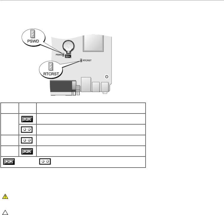
Jumper Settings
Jumper Setting |
Description |
PSWD |
Password features are enabled (default setting). |
|
Password features are disabled. |
RTCRST |
The real-time clock has not been reset. |
|
The real-time clock is being reset (jumpered temporarily). |
jumpered |
unjumpered |
|
|
Clearing Forgotten Passwords
WARNING: Before working inside your computer, read the safety information that shipped with your computer. For additional safety best practices information, see the Regulatory Compliance Homepage at www.dell.com/regulatory_compliance.
CAUTION: This process erases both the system and administrator passwords.

1.Follow the procedures in Working on Your Computer.
2.Remove the computer cover.
3.Locate the 2-pin password jumper (PSWD) on the system board, and remove the jumper to clear the password. See Password Protection.
4.Replace the computer cover.
5.Connect your computer and monitor to electrical outlets, and turn them on.
6.After the Microsoft® Windows® desktop appears on your computer, shut down your computer.
7.Turn off the monitor and disconnect it from the electrical outlet.
8.Disconnect the computer power cable from the electrical outlet, and press the power button to ground the system board.
9.Open the computer cover.
10.Locate the 2-pin password jumper on the system board and attach the jumper to reenable the password feature.
11.Replace the computer cover.
CAUTION: To connect a network cable, first plug the cable into the network wall jack and then plug it into the computer.
12. Connect your computer and devices to electrical outlets, and turn them on.
NOTE: This procedure enables the password feature. When you enter system setup (see Entering System Setup), both system and administrator password options appear as Not Set—meaning that the password feature is enabled but no password is assigned.
13. Assign a new system and/or administrator password.
Clearing CMOS Settings
WARNING: Before working inside your computer, read the safety information that shipped with your computer. For additional safety best practices information, see the Regulatory Compliance Homepage at www.dell.com/regulatory_compliance.
1.Follow the procedures in Working on Your Computer.
2.Remove the cover.
3.Reset the current CMOS settings:
a.Locate the password (PSWD) and CMOS (RTCRST) jumpers on the system board (see Password Protection).
b.Remove the password jumper plug from its pins.
c.Place the password jumper plug on the RTCRST pins and wait approximately 5 seconds.
d.Remove the jumper plug from the RTCRST pins and place it back on the password pins.
4.Replace the computer cover.
CAUTION: To connect a network cable, first plug the cable into the network wall jack and then plug it into the computer.
5. Connect your computer and devices to electrical outlets, and turn them on.
Back to Contents Page
Back to Contents Page
Diagnostics
Dell™ OptiPlex™ 780 Ultra Small Form Factor—Service Manual
 Dell Diagnostics
 Power Button Light Codes
 Beep Codes
 Diagnostic Lights
Dell Diagnostics
When to Use the Dell Diagnostics
It is recommended that you print these procedures before you begin.
NOTE: The Dell Diagnostics software works only on Dell computers.
NOTE: The Drivers and Utilities media is optional and may not ship with your computer.
Enter system setup (see Entering System Setup), review your computer's configuration information, and ensure that the device you want to test displays in System Setup and is active.
Start the Dell Diagnostics from either your hard drive or from the Drivers and Utilities media.
Starting the Dell Diagnostics From Your Hard Drive
1.Turn on (or restart) your computer.
2.When the DELL logo appears, press <F12> immediately.
NOTE: If you see a message stating that no diagnostics utility partition has been found, run the Dell Diagnostics from your Drivers and Utilities media.
If you wait too long and the operating system logo appears, continue to wait until you see the Microsoft® Windows® desktop. Then shut down your computer and try again.
3.When the boot device list appears, highlight Boot to Utility Partition and press <Enter>.
4.When the Dell Diagnostics Main Menu appears, select the test that you want to run.
Starting the Dell Diagnostics From the Drivers and Utilities Disc
1.Insert the Drivers and Utilities disc.
2.Shut down and restart the computer.
When the DELL logo appears, press <F12> immediately.
If you wait too long and the Windows logo appears, continue to wait until you see the Windows desktop. Then shut down your computer and try again.
NOTE: The next steps change the boot sequence for one time only. On the next startup, the computer boots according to the devices specified in the system setup program.
3.When the boot device list appears, highlight Onboard or USB CD-ROM Drive and press <Enter>.
4.Select the Boot from CD-ROM option from the menu that appears and press <Enter>.
5.Type 1 to start the menu and press <Enter> to proceed.
6.Select Run the 32 Bit Dell Diagnostics from the numbered list. If multiple versions are listed, select the version appropriate for your computer.
7.When the Dell Diagnostics Main Menu appears, select the test you want to run.
Dell Diagnostics Main Menu
1. After the Dell Diagnostics loads and the Main Menu screen appears, click the button for the option you want.
Option |
Function |
Express |
Performs a quick test of devices. This test typically takes 10 to 20 minutes and requires no interaction on |
Test |
your part. Run Express Test first to increase the possibility of tracing the problem quickly. |
Extended |
Performs a thorough check of devices. This test typically takes 1 hour or more and requires you to answer |
Test |
questions periodically. |
Custom |
Tests a specific device. You can customize the tests you want to run. |
Test |
|
Symptom |
Lists the most common symptoms encountered and allows you to select a test based on the symptom of the |
Tree |
problem you are having. |
2.If a problem is encountered during a test, a message appears with an error code and a description of the problem. Write down the error code and problem description and follow the instructions on the screen.
3.If you run a test from the Custom Test or Symptom Tree option, click the applicable tab described in the following table for more information.
Tab |
Function |
Results |
Displays the results of the test and any error conditions encountered. |
Errors |
Displays error conditions encountered, error codes, and the problem description. |
Help |
Describes the test and may indicate requirements for running the test. |
Configuration Displays your hardware configuration for the selected device.
The Dell Diagnostics obtains configuration information for all devices from system setup, memory, and various internal tests, and it displays the information in the device list in the left pane of the screen. The device list may not display the names of all the components installed on your computer or all devices attached to your computer.
Parameters |
Allows you to customize the test by changing the test settings. |
4.When the tests are completed, if you are running the Dell Diagnostics from the Drivers and Utilities disc, remove the disc.
5.Close the test screen to return to the Main Menu screen. To exit the Dell Diagnostics and restart the computer, close the Main Menu screen.
Power Button Light Codes
The diagnostic lights give much more information about the system state, but legacy power light states are also supported in your computer. The power light states are shown in following table.
Power
Light
State
Off
Blinking
Amber
Solid
Description
Power is off, light is blank.
Initial state of light at power up.
Indicates system has power, but the POWER_GOOD signal is not yet active.
If the Hard Drive light is off, it is probable that the power supply needs to be replaced.
If the Hard Drive light on, it is probable that an onboard regulator or VRM has failed. Look at the diagnostic lights for further information.
 Loading...