


Dell™ Dimension™ E521 Service Manual
Before You Begin
About Your Computer
Technical Overview
Specifications
Advanced Troubleshooting
System Setup
Removing and Installing Parts
Model DCSM
Notes, Notices, and Cautions
NOTE: A NOTE indicates important information that helps you make better use of your computer.
NOTICE: A NOTICE indicates either potential damage to hardware or loss of data and tells you how to avoid the problem.
CAUTION: A CAUTION indicates a potential for property damage, personal injury, or death.
If you purchased a Dell™ n Series computer, any references in this document to Microsoft® Windows® operating systems are not applicable.
Information in this document is subject to change without notice.
© 2006 Dell Inc. All rights reserved.
Reproduction in any manner whatsoever without the written permission of Dell Inc. is strictly forbidden.
Trademarks used in this text: Dell, the DELL logo, and Dimension are trademarks of Dell Inc.; Microsoft and Windows are registered trademarks of Microsoft Corporation; AMD, Athlon, and Sempron are trademarks of Advanced Micro Devices, Inc.
Other trademarks and trade names may be used in this document to refer to either the entities claiming the marks and names or their products. Dell Inc. disclaims any proprietary interest in trademarks and trade names other than its own.
September 2006 Rev. A00
Back to Contents Page
About Your Computer
Dell™ Dimension™ E521 Service Manual
Front View of the Computer
Back View of the Computer
Back Panel Connectors
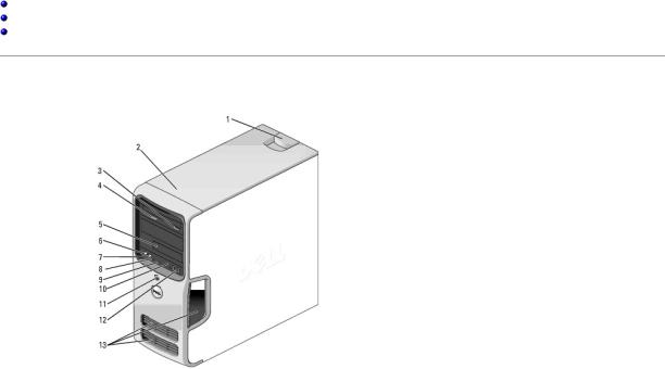
Front View of the Computer
1 |
cover latch |
Use this latch to remove the cover. See Removing the Computer Cover. |
|
release |
|
|
|
|
2 |
location of |
Use the Service Tag to identify your computer when you access the Dell |
|
Service Tag |
Support website or call technical support. |
3 |
CD or DVD |
Press to eject a disk from the CD or DVD drive. |
|
eject button |
|
4 |
CD or DVD |
The drive light is on when the computer reads data from the CD or DVD |
|
activity light |
drive. |
|
|
|
5 |
FlexBay drive |
Can contain an optional floppy drive or optional Media Card Reader. For |
|
|
information on using the Media Card Reader, see "Using a Media Card |
|
|
Reader (Optional) in your Owner's Manual. |
6 |
microphone |
Use the microphone connector to attach a personal computer |
|
connector |
microphone for voice or musical input into a sound or telephony |
|
|
program. |
|
|
On computers with a sound card, the microphone connector is on the |
|
|
card. |
|
|
|
7 |
headphone |
Use the headphone connector to attach headphones and most kinds of |
|
connector |
speakers. |
|
|
|
8 |
LAN indicator |
This light indicates that a LAN (local area network) connection is |
|
light |
established. |
9 |
diagnostic |
Use the lights to help you troubleshoot a computer problem based on |
|
lights (4) |
the diagnostic code. For more information, see Diagnostic Lights. |
|
|
|
10 |
hard-drive |
The hard-drive activity light is on when the computer reads data from or |
|
activity light |
writes data to the hard drive. The light might also be on when a device |
|
|
such as a CD player is operating. |
|
|
|
11 |
power button, |
Press the power button to turn on the computer. The light in the center |
|
power light |
of this button indicates power state. |
|
|
NOTICE: To avoid losing data, do not use the power button to turn off |
|
|
the computer. Instead, perform an operating system shutdown. |
|
|
|
12 |
USB 2.0 |
Use the front USB connectors for devices that you connect occasionally, |
|
connectors (2) |
such as joysticks or cameras, or for bootable USB devices (see System |
|
|
Setup Options for more information on booting to a USB device). |
|
|
It is recommended that you use the back USB connectors for devices |
|
|
that typically remain connected, such as printers and keyboards. |
|
|
|
13 |
vents |
For adequate cooling, do not block any of the vents. |
|
|
|
NOTICE: Ensure that there is a minimum of two inches of space between all vents and any object near these vents.
NOTICE: Keep the vent area clean and dust-free to ensure that the computer is adequately ventilated. Use only a dry cloth to clean the vent area to avoid water damage to the computer.
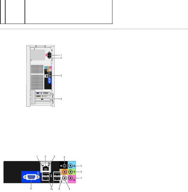
Back View of the Computer
1 |
voltage selection |
See the safety instructions in the Product Information Guide for more |
|
|
switch |
information. |
|
|
|
|
|
2 |
power connector |
Insert the power cable. |
|
|
|
|
|
3 |
back panel |
Plug USB, audio, and other devices into the appropriate connector. |
|
|
connectors |
See Back Panel Connectors for more information. |
|
|
|
|
|
4 |
card slots |
Access connectors for any installed PCI and PCI Express cards. |
|
|
|
|
|
Back Panel Connectors
1 |
link integrity light |
• Green — A good connection exists between a 10-Mbps |
|
|
network and the computer. |
|
|
• Orange — A good connection exists between a 100-Mbps |
|
|
network and the computer. |
|
|
• Off — The computer is not detecting a physical connection to |
|
|
the network. |
|
|
|
2 |
network adapter |
To attach your computer to a network or broadband device, connect |
|
connector |
one end of a network cable to either a network port or your |
|
|
network or broadband device. Connect the other end of the |
|
|
network cable to the network adapter connector on the back panel |
|
|
of your computer. A click indicates that the network cable has been |
|
|
securely attached. |
|
|
NOTE: Do not plug a telephone cable into the network connector. |
|
|
On computers with a network connector card, use the connector on |
|
|
the card. |
|
|
It is recommended that you use Category 5 wiring and connectors |
|
|
for your network. If you must use Category 3 wiring, force the |
|
|
network speed to 10 Mbps to ensure reliable operation. |
|
3 |
network activity |
Flashes a yellow light when the computer is transmitting or |
|
|
light |
receiving network data. A high volume of network traffic may make |
|
|
|
this light appear to be in a steady "on" state. |
|
4 |
surround |
Use the black surround connector to attach multichannel-capable |
|
|
connector |
speakers. |
|
|
|
|
|
5 |
line-in connector |
Use the blue line-in connector to attach a record/playback device |
|
|
|
such as a cassette player, CD player, or VCR. |
|
|
|
On computers with a sound card, use the connector on the card. |
|
|
|
|
|
6 |
line-out connector |
Use the green line-out connector (available on computers with |
|
|
|
integrated sound) to attach headphones and most speakers with |
|
|
|
integrated amplifiers. |
|
|
|
On computers with a sound card, use the connector on the card. |
|
|
|
|
|
7 |
microphone |
Use the pink connector to attach a personal computer microphone |
|
|
|
for voice or musical input into a sound or telephony program. |
|
|
|
On computers with a sound card, the microphone connector is on |
|
|
|
the card. |
|
8 |
side surround |
Use the silver connector to provide enhanced surround audio for |
|
|
connector |
computers with 7.1 speakers. |
|
|
|
On computers with a sound card, the microphone connector is on |
|
|
|
the card. |
|
|
|
|
|
9 |
center/subwoofer |
Use the yellow connector to attach a speaker to a Low Frequency |
|
|
connector |
Effects (LFE) audio channel. |
|
10 |
USB 2.0 connectors |
Use the back USB connectors for devices that typically remain |
|
|
(4) |
connected, such as printers and keyboards. |
|
|
|
It is recommended that you use the front USB connectors for |
|
|
|
devices that you connect occasionally, such as joysticks or cameras. |
|
|
|
|
|
11 |
VGA video |
Connect the monitor's VGA cable to the VGA connector on the |
|
|
connector |
computer. |
|
|
|
On computers with a video card, use the connector on the card. |
|
|
|
|
|
|
|
|
|
Back to Contents Page |
|
|
|

Back to Contents Page
Advanced Troubleshooting
Dell™ Dimension™ E521 Service Manual
Power Lights
Diagnostic Lights
Beep Codes
System Messages
Dell Diagnostics
Drivers
Resolving Software and Hardware Incompatibilities
Power Lights
CAUTION: Before you begin any of the procedures in this section, follow the safety instructions in the Product Information Guide.
The power button light located on the front of the computer illuminates and blinks or remains solid to indicate different states:
•If the power light is green and the computer is not responding:
¡Ensure the display is connected and powered on.
¡If the display is connected and powered on, see Diagnostic Lights.
•If the power light is blinking green, the computer is in standby mode. Press a key on the keyboard, move the mouse, or press the power button to resume normal operation.
•If the power light is off, the computer is either turned off or is not receiving power.
¡Reseat the power cable in the power connector on the back of the computer and the electrical outlet.
¡If the computer is plugged into a power strip, ensure that the power strip is plugged into an electrical outlet and that the power strip is turned on. Also, bypass power protection devices, power strips, and power extension cables to verify that the computer turns on properly.
¡Ensure that the electrical outlet is working by testing it with another device, such as a lamp.
¡Ensure that the main power cable and front panel cable are securely connected to the system board (see System Board Components).
•If the power light is blinking amber, the computer is receiving electrical power, but an internal power problem might exist.
¡Ensure that the voltage selection switch is set to match the AC power at your location (if applicable).
•If the power light is steady amber, a device might be malfunctioning or incorrectly installed.
¡Remove and then reinstall the memory modules (see Memory).
¡Remove and then reinstall any cards (see Cards).
¡Remove and then reinstall the graphics card, if applicable (see Cards).
¡Ensure that all power cables are securely connected to the system board (see System Board Components).
Diagnostic Lights
CAUTION: Before you perform any of the procedures in this section, follow the safety instructions in the Product Information Guide.
To help you troubleshoot a problem, your computer has four lights labeled 1, 2, 3, and 4 on the front panel (see Front View of the Computer). When the computer starts normally, the lights flash before turning off. If the computer malfunctions, the sequence of the lights helps to identify the problem.
Light Pattern |
Problem Description |
Suggested Resolution |
|
|
|
|
The computer is in a normal "off" |
Plug the computer into a working electrical outlet and press the power button. |
|
condition, or a possible pre-BIOS failure |
|
|
has occurred. |
|
|
The diagnostic lights are not lit after the |
|
|
computer successfully boots to the |
|
|
operating system. |
|
|
|
|
|
A possible BIOS failure has occurred; the |
Run the BIOS Recovery utility, wait for recovery completion, and then restart the computer. |
|
computer is in the recovery mode. |
|
|
|
|
|
A possible processor failure has |
Contact Dell (see "Contacting Dell" in your Owner's Manual). |
|
occurred. |
|
|
|
|

|
|
|
|
Memory modules are detected, but a |
• If you have two or more memory modules installed, remove the modules, reinstall one |
|
memory failure has occurred. |
module (see Installing Memory), and then restart the computer. If the computer starts |
|
|
normally, reinstall an additional module. Continue until you have identified a faulty |
|
|
module or reinstalled all modules without error. |
|
|
• If available, install properly working memory of the same type into your computer (see |
|
|
Installing Memory). |
|
|
• If the problem persists, contact Dell (see "Contacting Dell" in your Owner's Manual). |
|
|
|
|
A possible graphics card failure has |
• If the computer has a graphics card, remove the card, reinstall it (see PCI Express |
|
occurred. |
Cards), and then restart the computer. |
|
|
• If the problem still exists, install a graphics card that you know works and restart the |
|
|
computer. |
|
|
• If the problem persists or the computer has integrated graphics, contact Dell (see |
|
|
"Contacting Dell" in your Owner's Manual). |
|
|
|
|
A possible floppy or hard drive failure |
Reseat all power and data cables and restart the computer. |
|
has occurred. |
|
|
|
|
|
A possible USB failure has occurred. |
Reinstall all USB devices, check cable connections, and then restart the computer. |
|
|
|
|
No memory modules are detected. |
• If you have two or more memory modules installed, remove the modules, reinstall one |
|
|
module (see Installing Memory), and then restart the computer. If the computer starts |
|
|
normally, reinstall an additional module. Continue until you have identified a faulty |
|
|
module or reinstalled all modules without error. |
|
|
• If available, install properly working memory of the same type into your computer (see |
|
|
Installing Memory). |
|
|
• If the problem persists, contact Dell (see "Contacting Dell" in your Owner's Manual). |
|
|
|
|
Memory modules are detected, but a |
• Ensure that no special memory module/memory connector placement requirements exist |
|
memory configuration or compatibility |
(see Memory Installation Guidelines). |
|
error exists. |
• Verify that the memory modules that you are installing are compatible with your |
|
|
computer (see Memory Installation Guidelines). |
|
|
• If the problem persists, contact Dell (see "Contacting Dell" in your Owner's Manual). |
|
|
|
|
Another failure has occurred. |
• Ensure that the cables are properly connected to the system board from the hard drive, |
|
|
CD drive, and DVD drive (see Drives). |
|
|
• If there is an error message on your screen identifying a problem with a device (such as |
|
|
the floppy drive or hard drive), check the device to ensure that it is functioning properly. |
|
|
• If the problem persists, contact Dell (see "Contacting Dell" in your Owner's Manual). |
|
|
|
|
After POST is complete, all four |
None. |
|
diagnostic lights turn green briefly |
|
|
before turning off to indicate normal |
|
|
operating condition. |
|
|
|
|
|
|
|
Beep Codes
Your computer might emit a series of beeps during start-up if the monitor cannot display errors or problems. This series of beeps, called a beep code, identifies a problem. One possible beep code consists of one long beep and then two short beeps. This beep code tells you that the computer encountered a memory test failure.
If your computer beeps during start-up:
1.Write down the beep code.
2.Run the Dell Diagnostics to identify a more serious cause (see Dell Diagnostics).
Code |
Cause |
|
|
|
|
2 short, 1 long |
BIOS checksum error |
|
|
|
|
1 long, 2 short |
Memory test failure (bad memory during memory sizing) |
|
1 long, 3 short, 2 short |
No memory |
|
|
|
|
1 short |
F12 key pressed |
|
|
|
|
|
|
|
System Messages
NOTE: If the message you received is not listed in the table, see the documentation for either the operating system or the program that was running when the message appeared.

A filename cannot contain any of the following characters: \ / : * ? " < > | — Do not use these characters in filenames.
A required .DLL file was not found — The program that you are trying to open is missing an essential file. To remove and then reinstall the program:
1.Click the Start button, click Control Panel, and then click Add or Remove Programs.
2.Select the program you want to remove.
3.Click the Change or Remove Program icon.
4.See the program documentation for installation instructions.
Attachment failed to respond — See "Drive Problems" in your Owner's Manual.
Bad command or file name — Ensure that you spelled the command correctly, put spaces in the proper place, and used the correct pathname.
Bad error-correction code (ECC) on disk read — See "Drive Problems" in your Owner's Manual.
Data error — See "Drive Problems" in your Owner's Manual.
Diskette drive 0 seek failure — See "Drive Problems" in your Owner's Manual.
Diskette read failure —
See "Drive Problems" in your Owner's Manual.
Diskette write protected — Slide the write-protect notch on the floppy disk to the open position.
Hard-disk drive failure —
See "Drive Problems" in your Owner's Manual.
No boot device detected — Insert a bootable floppy disk or CD.
Invalid configuration information - please run SETUP program — Enter system setup and correct the computer configuration information (see Entering System Setup).
Keyboard failure — See "Keyboard Problems" in your Owner's Manual.
Memory allocation error —
1.Turn off the computer, wait 30 seconds, and then restart the computer.
2.Try to run the program again.
3.If the error message appears again, see the software documentation for additional troubleshooting suggestions.
No boot device available —
•If the floppy drive is your boot device, ensure that a bootable floppy disk is in the drive.
•If the hard drive is your boot device, ensure that the cables are connected and that the drive is installed properly and partitioned as a boot device.
•Enter system setup and ensure that the boot sequence information is correct (see Entering System Setup).
Non-system disk error — Remove the floppy disk from the drive and restart your computer.
Non-system disk or disk error — Replace the floppy disk with one that has a bootable operating system or remove the floppy disk from drive A and restart the computer.
Not a boot diskette — Insert a bootable floppy disk and restart your computer.

Not enough memory or resources. Close some programs and try again — Close all windows and open the program that you want to use. In some cases, you might have to restart your computer to restore computer resources. If so, run the program that you want to use first.
Read fault —
Requested sector not found —
Reset failed —
See "Drive Problems" in your Owner's Manual.
Sector not found —
•Run the Windows error-checking utility to check the file structure on the floppy disk or hard drive. See Windows Help for instructions.
•If a large number of sectors are defective, back up the data (if possible), and then reformat the floppy disk or hard drive.
Seek error — See "Drive Problems" in your Owner's Manual.
Shutdown failure — Run the Dell Diagnostics.
Unexpected interrupt in protected mode — Run the Dell Diagnostics.
WARNING: Dell's Disk Monitoring System has detected that drive [0/1] on the [primary/secondary] EIDE controller is operating outside of normal specifications. It is advisable to immediately back up your data and replace your hard drive by calling your support desk or Dell —
If no replacement drive is immediately available and the drive is not the only bootable drive, enter system setup and change the appropriate drive setting to None. Then remove the drive from the computer (see Entering System Setup).
<drive letter>:\ is not accessible. The device is not ready — The selected drive cannot read its medium. Depending on its medium type, insert a floppy, CD, or Zip disk into the drive and try again.
Dell Diagnostics
CAUTION: Before you begin any of the procedures in this section, follow the safety instructions in the Product Information Guide.
NOTE: The Dell Diagnostics only operate on Dell computers.
Starting the Dell Diagnostics
1.Turn on (or restart) your computer.
2.When the DELL logo appears, press <F12> immediately.
NOTE: Keyboard failure may result when a key is held down for extended periods of time. To avoid possible keyboard failure, press and release <F12> in even intervals to open the Boot Device Menu.
If you wait too long and the operating system logo appears, continue to wait until you see the Microsoft® Windows® desktop, then shut down your computer and try again.
3.At the Boot Device Menu, use the upand down-arrow keys or press the appropriate number on the keyboard to highlight Boot to Utility Partition, and then press <Enter>.
NOTE: The Quickboot feature changes the boot sequence for the current boot only. Upon restart, the computer boots according to the boot sequence specified in system setup.
4.At the Dell Diagnostics Main Menu, left-click with the mouse, or press <Tab> and then <Enter>, to select the test you want to run (see Dell Diagnostics Main Menu).
NOTE: Write down any error codes and problem descriptions exactly as they appear and follow the instructions on the screen.

5.After all tests have completed, close the test window to return to the Dell Diagnostics Main Menu.
6.Close the Main Menu window to exit the Dell Diagnostics and restart the computer.
Dell Diagnostics Main Menu
1. After the Dell Diagnostics loads and the Main Menu screen appears, click the button for the option you want.
Option |
Function |
|
|
Express Test |
Performs a quick test of devices. This test typically takes 10 to 20 minutes and requires no interaction on your part. Run Express Test first to |
|
increase the possibility of tracing the problem quickly. |
|
|
Extended |
Performs a thorough check of devices. This test typically takes an hour or more and requires you to answer questions periodically. |
Test |
|
Custom Test |
Tests a specific device. You can customize the tests you want to run. |
|
|
Symptom |
Lists the most common symptoms encountered and allows you to select a test based on the symptom of the problem you are having. |
Tree |
|
|
|
2.If a problem is encountered during a test, a message appears with an error code and a description of the problem. Write down the error code and problem description and follow the instructions on the screen.
If you cannot resolve the error condition, contact Dell (see "Contacting Dell" in your Owner's Manual).
NOTE: The Service Tag for your computer is located at the top of each test screen. If you contact Dell, technical support will ask for your Service Tag.
3. If you run a test from the Custom Test or Symptom Tree option, click the applicable tab described in the following table for more information.
Tab |
Function |
|
|
Results |
Displays the results of the test and any error conditions encountered. |
Errors |
Displays error conditions encountered, error codes, and the problem description. |
|
|
Help |
Describes the test and may indicate requirements for running the test. |
|
|
Configuration |
Displays your hardware configuration for the selected device. |
|
The Dell Diagnostics obtains configuration information for all devices from system setup, memory, and various internal tests, and it displays |
|
the information in the device list in the left pane of the screen. The device list may not display the names of all the components installed on |
|
your computer or all devices attached to your computer. |
|
|
Parameters |
Allows you to customize the test by changing the test settings. |
|
|
4. Close the test screen to return to the Main Menu screen. To exit the Dell Diagnostics and restart the computer, close the Main Menu screen.
Drivers
What Is a Driver?
A driver is a program that controls a device such as a printer, mouse, or keyboard. All devices require a driver program.
A driver acts as a translator between the device and any other programs that use the device. Each device has its own set of specialized commands that only the driver for that device recognizes.
Required drivers are already installed on your computer—no further installation or configuration is needed.
Many drivers, such as the keyboard driver, come with your Microsoft® Windows® operating system. You may need to install drivers if you:
•Upgrade your operating system.
•Reinstall your operating system.
•Connect or install a new device.
Identifying Drivers

If you experience a problem with any device, identify whether the driver is the source of your problem and, if necessary, update the driver.
Windows XP
1.Click the Start button, then click Control Panel.
2.Under Pick a Category, click Performance and Maintenance.
3.Click System.
4.In the System Properties window, click the Hardware tab.
5.Click Device Manager.
6.Scroll down the list of devices and check for an exclamation point (a circle with a [!]) next to the device name.
If an exclamation point appears next to the device name, you may need to reinstall the driver or install a new driver.
Reinstalling Drivers
NOTICE: The Dell Support website at support.dell.com provides approved drivers for your Dell™ computer. If you install drivers obtained from other sources, your computer may not function properly.
Using Windows XP Device Driver Rollback
If a problem occurs on your computer after you install or update a driver, use Windows XP Device Driver Rollback to replace the driver with the previously installed version.
1.Click Start, then click Control Panel.
2.Under Pick a Category, click Performance and Maintenance.
3.Click System.
4.In the System Properties window, click the Hardware tab.
5.Click Device Manager.
6.Right-click the device for which the new driver was installed, then click Properties.
7.Click the Driver tab.
8.Click Roll Back Driver.
Manually Reinstalling Drivers
1.After copying the required driver files to your hard drive, click the Start button and right-click My Computer.
2.Click Properties.
3.Click the Hardware tab and click Device Manager.
4.Double-click the type of device for which you are installing the driver.
5.Double-click the name of the device for which you are installing the driver.
6.Click the Driver tab and click Update Driver.
7.Click Install from a list or specific location (Advanced) and click Next.
8.Click Browse and browse to the location to which you previously extracted the driver files.
9.When the name of the appropriate driver appears, click Next.
10. Click Finish and restart your computer.
Resolving Software and Hardware Incompatibilities
If a device is not detected during the operating system setup or is detected but incorrectly configured, you can use the Hardware Troubleshooter to resolve the incompatibility.
To resolve incompatibilities using the Hardware Troubleshooter:
1.Click Start, then click Help and Support.
2.Type hardware troubleshooter in the Search field, then click the arrow to start the search.
3.Click Hardware Troubleshooter in the Search Results list.
4.In the Hardware Troubleshooter list, click I need to resolve a hardware conflict on my computer, and then click Next.
Back to Contents Page

Back to Contents Page
Before You Begin
Dell™ Dimension™ E521 Service Manual
Getting Started
Recommended Tools
Turning Off Your Computer
Before Working Inside Your Computer
Getting Started
This manual provides procedures for removing and replacing the components in your computer. Unless otherwise noted, each procedure assumes that the following conditions exist:
•You have performed the steps in Turning Off Your Computer and Before Working Inside Your Computer.
•You have read the safety information in your Dell™ Product Information Guide.
•A component can be installed by performing the removal procedure in reverse order.
Recommended Tools
The procedures in this document may require the following tools:
•Small flat-blade screwdriver
•Phillips screwdriver
•Flash BIOS update program (download)
Turning Off Your Computer
NOTICE: To avoid losing data, save and close any open files and exit any open programs before you turn off your computer.
1.Shut down the operating system:
a.Save and close any open files, exit any open programs, click the Start button, and then click Shutdown.
b.In the Shut Down Windows window, select Shut down.
The computer turns off after the operating system shutdown process finishes.
2.Ensure that the computer and any attached devices are turned off. If your computer and attached devices did not automatically turn off when you shut down your operating system, press and hold the power button for 4 seconds.
Before Working Inside Your Computer
Use the following safety guidelines to help protect your computer from potential damage and to help ensure your own personal safety.
CAUTION: Before you begin any of the procedures in this section, follow the safety instructions in the Product Information Guide.
CAUTION: Handle components and cards with care. Do not touch the components or contacts on a card. Hold a card by its edges or by its metal mounting bracket. Hold a component such as a processor by its edges, not by its pins.
NOTICE: Only a certified service technician should perform repairs on your computer. Damage due to servicing that is not authorized by Dell is not covered by your warranty.
NOTICE: When you disconnect a cable, pull on its connector or on its strain-relief loop, not on the cable itself. Some cables have a connector with locking tabs; if you are disconnecting this type of cable, press in on the locking tabs before you disconnect the cable. As you pull connectors apart, keep them evenly aligned to avoid bending any connector pins. Also, before you connect a cable, ensure that both connectors are correctly oriented and aligned.
NOTICE: To avoid damaging the computer, perform the following steps before you begin working inside the computer.
1. Turn off your computer. See Turning Off Your Computer.

NOTICE: To disconnect a network cable, first unplug the cable from your computer, and then unplug it from the network port or device.
2.Disconnect any telephone or telecommunication lines from the computer.
3.Disconnect your computer and all attached devices from their electrical outlets, and then press the power button to ground the system board.
NOTICE: Before touching anything inside your computer, ground yourself by touching an unpainted metal surface, such as the metal at the back of the computer. While you work, periodically touch an unpainted metal surface to dissipate any static electricity that could harm internal components.
Back to Contents Page

Back to Contents Page
Removing and Installing Parts
Dell™ Dimension™ E521 Service Manual
Removing the Computer Cover
Memory
Cards
Drive Panel
Drives
Hard Drive
Floppy Drive
Media Card Reader
CD/DVD Drive
Battery
Power Supply
Processor
I/O Panel
Processor Fan
System Board
Installing the Computer Cover
This chapter provides procedures for removing and installing the components in your computer. Unless otherwise noted, each procedure assumes that the following conditions exist:
•You have performed the steps in Turning Off Your Computer and Before Working Inside Your Computer.
•You have read the safety information in your Dell™ Product Information Guide.
•A component can be replaced by performing the removal procedure in reverse order.
•You have the tools listed in Recommended Tools.
Removing the Computer Cover
CAUTION: Before you begin any of the procedures in this section, follow the safety instructions in the Product Information Guide.
CAUTION: To guard against electrical shock, always unplug your computer from the electrical outlet before removing the cover.
CAUTION: When working inside the computer, be aware that the heat sink assembly, power supply, and other components may be very hot during normal operation. Be sure that components have had sufficient time to cool before you touch them.
NOTICE: To prevent static damage to components inside your computer, discharge static electricity from your body before you touch any of your computer's electronic components. You can do so by touching an unpainted metal surface on the computer chassis.
1. Follow the procedures in Before You Begin.
NOTICE: Ensure that sufficient space exists to support the removed cover—at least 30 cm (1 ft) of desk top space.
NOTICE: Ensure that you are working on a level, protected surface to avoid scratching either the computer or the surface on which it is resting.
2.Lay your computer on its side with the computer cover facing up.
3.Pull back the cover release latch located on the top panel.
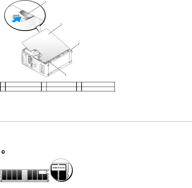
1 cover latch release |
2 computer cover |
3 back of computer |
4bottom hinge tabs
4.Locate the three hinge tabs on the bottom edge of the computer.
5.Grip the sides of the computer cover and pivot the cover up, using the bottom hinge tabs as leverage points.
6.Release the cover from the hinge tabs and set it aside in a secure location.
Memory
You can increase your computer memory by installing memory modules on the system board.
Your computer supports DDR2 memory. For additional information on the type of memory supported by your computer, see Memory.
NOTICE: Do not install ECC or buffered memory modules. Only unbuffered, non-ECC memory is supported.
Memory Installation Guidelines
•DIMM connectors must be populated in numerical order beginning with connectors DIMM_1 and DIMM_2, then connectors DIMM_3 and DIMM_4.
If a single DIMM is installed, you must install it in connector DIMM_1.
•For best performance, memory modules should be installed in pairs of matched memory size, speed, and technology. If the memory modules are not installed in matched pairs, the computer will operate, but with a slight reduction in performance. (See the label on the module to determine the module's capacity.) For example, if you install a mixed pair of DDR2 533-MHz and DDR2 667-MHz memory, the modules function at the slowest speed installed.
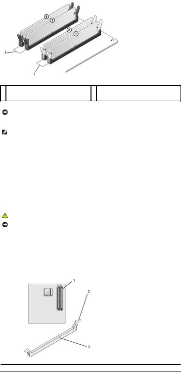
1Channel A: matched pair of memory modules in connectors DIMM_1 and DIMM_2 (white securing clips)
2Channel B: matched pair of memory modules in connectors DIMM_3 and DIMM_4 (black securing clips)
NOTICE: If you remove your original memory modules from the computer during a memory upgrade, keep them separate from any new modules that you may have, even if you purchased the new modules from Dell. If possible, do not pair an original memory module with a new memory module. Otherwise, your computer may not start properly. You should install your original memory modules in pairs either in DIMM connectors 1 and 2 or DIMM connectors 3 and 4.
NOTE: Memory purchased from Dell is covered under your computer warranty.
Addressing Memory With 4-GB Configurations
Your computer supports a maximum of 4 GB of memory when you use four 1-GB DIMMs. Current 32-bit operating systems, such as Microsoft® Windows® XP, can use a maximum of 4 GB of address space; however, the amount of memory available to the operating system is less than that installed. Certain components within the computer require address space in the 4-GB range. Any address space reserved for these components cannot be used by computer memory.
Installing Memory
CAUTION: Before you begin any of the procedures in this section, follow the safety instructions in the Product Information Guide.
NOTICE: To prevent static damage to components inside your computer, discharge static electricity from your body before you touch any of your computer's electronic components. You can do so by touching an unpainted metal surface on the computer chassis.
1.Follow the procedures in Before You Begin.
2.Remove the computer cover (see Removing the Computer Cover).
3.Press the securing clip at each end of the memory module connector.
 1
1  memory connector farthest from processor (DIMM_1)
  2
2  securing clips (2)
  3
3  connector
4. Align the notch on the bottom of the module with the crossbar in the connector.
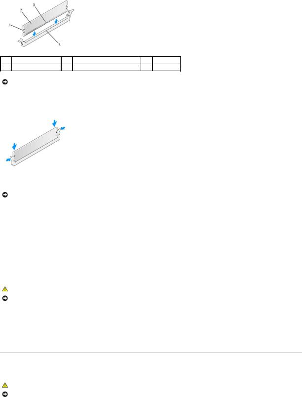
1 |
cutouts (2) |
2 |
memory module |
3 |
notch |
4 crossbar
NOTICE: To avoid damage to the memory module, press the module straight down into the connector while you apply equal force to each end of the module.
5.Insert the module into the connector until the module snaps into position.
If you insert the module correctly, the securing clips snap into the cutouts at each end of the module.
6. Replace the computer cover.
NOTICE: To connect a network cable, first plug the cable into the network device and then plug it into the computer.
7.Connect your computer and devices to electrical outlets, and turn them on.
8.Right-click the My Computer icon and click Properties.
9.Click the General tab.
10.To verify that the memory is installed correctly, check the amount of memory (RAM) listed.
Removing Memory
CAUTION: Before you begin any of the procedures in this section, follow the safety instructions in the Product Information Guide.
NOTICE: To prevent static damage to components inside your computer, discharge static electricity from your body before you touch any of your computer's electronic components. You can do so by touching an unpainted metal surface on the computer chassis.
1.Follow the procedures in Before You Begin.
2.Press out the securing clip at each end of the memory module connector.
3.Grasp the module and pull up.
Cards
CAUTION: Before you begin any of the procedures in this section, follow the safety instructions in the Product Information Guide.
NOTICE: To prevent static damage to components inside your computer, discharge static electricity from your body before you touch any of your computer's electronic components. You can do so by touching an unpainted metal surface on the computer chassis.
Your Dell™ computer provides the following slots for PCI and PCI Express cards:
•One PCI Express x16 card slot (SLOT1)
•One PCI Express x1 card slot (SLOT2
•Two PCI card slots (SLOT3, SLOT4)
See System Board Components for card slot location.
PCI Cards
Your computer supports two PCI cards.
If you are installing or replacing a card, follow the procedures in the next section. If you are removing but not replacing a PCI card, see Removing a PCI Card.
If you are replacing a card, remove the current driver for the card from the operating system.
If you are installing or replacing a PCI Express card, see Installing a PCI Express Card.
Installing a PCI Card
1.Follow the procedures in Before You Begin.
2.Remove the computer cover (see Removing the Computer Cover).
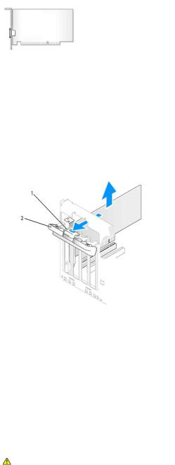
1 |
release tab |
2 |
card retention door |
|
|
|
|
3.Gently push the release tab on the card retention door from the inside to pivot the door open. The door is hinged and will remain in the open position.
4.If you are installing a new card, remove the filler bracket to create a card-slot opening. Then continue with step 6.
5.If you are replacing a card that is already installed in the computer, remove the card.
If necessary, disconnect any cables connected to the card. Grasp the card by its top corners, and ease it out of its connector.
6.Prepare the card for installation.
See the documentation that came with the card for information on configuring the card, making internal connections, or otherwise customizing it for your computer.
CAUTION: Some network adapters automatically start the computer when they are connected to a network. To guard against electrical shock, be sure to unplug your computer from its electrical outlet before installing any cards.
7. Place the card in the connector and press down firmly. Ensure that the card is fully seated in the slot.
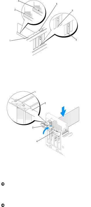
1 |
alignment bar |
2 |
fully seated card |
3 |
not fully seated card |
|
|
|
|
|
|
4 |
alignment guide |
5 |
bracket within slot |
6 |
bracket caught outside of slot |
|
|
|
|
|
|
8. Before you close the card retention door, ensure that:
•The tops of all cards and filler brackets are flush with the alignment bar.
•The notch in the top of the card or filler bracket fits around the alignment guide.
1 |
alignment guide |
2 |
alignment bar |
3 |
release tab |
|
|
|
|
|
|
4 |
card retention door |
|
|
|
|
|
|
|
|
|
|
9. Close the card retention door by snapping it into place to secure the cards.
NOTICE: Do not route card cables over or behind the cards. Cables routed over the cards can prevent the computer cover from closing properly or cause damage to the equipment.
10.On a new card, connect any cables that are part of the installation. See the documentation for the card for information about the card's cable connections. On a replacement card, connect any cables that you removed in step 5.
NOTICE: To connect a network cable, first plug the cable into the network device and then plug it into the computer.
11.Replace the computer cover (see Installing the Computer Cover).
12.Connect your computer and devices to electrical outlets and turn them on.
13.If you installed a sound card:
a.Enter system setup (see System Setup), go to Onboard Devices and select Integrated Audio, and then change the setting to Off.
b.Connect external audio devices to the sound card's connectors. Do not connect external audio devices to the microphone, speaker/headphone, or line-in connectors on the back panel.
 Loading...