


 Loading...
Service Manual
LBP7200 Series
LBP7200Cdn
Feb 4 2009
Application
This manual has been issued by Canon Inc. for qualified persons to learn technical theory, installation, maintenance, and repair of products. This manual covers all localities where the products are sold. For this reason, there may be information in this manual that does not apply to your locality.
Corrections
This manual may contain technical inaccuracies or typographical errors due to improvements or changes in products. When changes occur in applicable products or in the contents of this manual, Canon will release technical information as the need arises. In the event of major changes in the contents of this manual over a long or short period, Canon will issue a new edition of this manual.
The following paragraph does not apply to any countries where such provisions are inconsistent with local law.
Trademarks
The product names and company names used in this manual are the registered trademarks of the individual companies.
Copyright
This manual is copyrighted with all rights reserved. Under the copyright laws, this manual may not be copied, reproduced or translated into another language, in whole or in part, without the written consent of Canon Inc.
COPYRIGHT © 2001 CANON INC.
Printed in Japan
Caution
Use of this manual should be strictly supervised to avoid disclosure of confidential information.

Introduction
Symbols Used
This documentation uses the following symbols to indicate special information:
Symbol Description
Indicates an item of a non-specific nature, possibly classified as Note, Caution, or Warning.
Indicates an item requiring care to avoid electric shocks.
Indicates an item requiring care to avoid combustion (fire).
Indicates an item prohibiting disassembly to avoid electric shocks or problems.
Indicates an item requiring disconnection of the power plug from the electric outlet.
Indicates an item intended to provide notes assisting the understanding of the topic in question.
Memo
Indicates an item of reference assisting the understanding of the topic in question.
REF.
Provides a description of a service mode.
Provides a description of the nature of an error indication.

Introduction
The following rules apply throughout this Service Manual:
1.Each chapter contains sections explaining the purpose of specific functions and the relationship between electrical and mechanical systems with reference to the timing of operation.
In the diagrams,  represents the path of mechanical drive; where a signal name accompanies the symbol , the arrow
  indicates the
direction of the electric signal.
The expression "turn on the power" means flipping on the power switch, closing the front door, and closing the delivery unit door, which results in supplying the machine with power.
2.In the digital circuits, '1'is used to indicate that the voltage level of a given signal is "High", while '0' is used to indicate "Low".(The voltage value, however, differs from circuit to circuit.) In addition, the asterisk (*) as in "DRMD*" indicates that the DRMD signal goes on when '0'.
In practically all cases, the internal mechanisms of a microprocessor cannot be checked in the field. Therefore, the operations of the microprocessors used in the machines are not discussed: they are explained in terms of from sensors to the input of the DC controller PCB and from the output of the DC controller PCB to the loads.
The descriptions in this Service Manual are subject to change without notice for product improvement or other purposes, and major changes will be communicated in the form of Service Information bulletins.
All service persons are expected to have a good understanding of the contents of this Service Manual and all relevant Service Information bulletins and be able to identify and isolate faults in the machine."

Contents
Contents
Chapter 1 PRODUCT DESCRIPTION |
|
1.1 Features ..................................................................................................................................................... |
1- 1 |
1.1.1 Feature .................................................................................................................................................................... |
1- 1 |
1.2 Product Specifications ................................................................................................................................ |
1- 1 |
1.2.1 Product Specifications ............................................................................................................................................. |
1- 1 |
1.3 Detailed Specifications ............................................................................................................................... |
1- 2 |
1.3.1 Print Speed.............................................................................................................................................................. |
1- 2 |
1.4 Name of Parts............................................................................................................................................. |
1- 3 |
1.4.1 External View........................................................................................................................................................... |
1- 3 |
1.4.2 Cross Sectional View............................................................................................................................................... |
1- 4 |
1.5 Using the Machine...................................................................................................................................... |
1- 5 |
1.5.1 Control Panel........................................................................................................................................................... |
1- 5 |
1.6 Safety ......................................................................................................................................................... |
1- 6 |
1.6.1 Safety of the Laser Light.......................................................................................................................................... |
1- 6 |
1.6.2 Safety of Toner ........................................................................................................................................................ |
1- 6 |
1.6.3 Handling the Laser Unit ........................................................................................................................................... |
1- 6 |
1.6.4 Points to note at disassembly/installation procedure............................................................................................... |
1- 7 |
Chapter 2 TECHNICAL REFERENCE |
|
2.1 Functional Configuration............................................................................................................................. |
2- 1 |
2.1.1 Outline ..................................................................................................................................................................... |
2- 1 |
2.2 Basic Sequense.......................................................................................................................................... |
2- 1 |
2.2.1 Basic Sequence of Operation.................................................................................................................................. |
2- 1 |
2.3 LASER EXPOSURE SYSTEM ................................................................................................................... |
2- 1 |
2.3.1 Overview/Configuration ........................................................................................................................................... |
2- 1 |
2.3.1.1 Outline...................................................................................................................................................................................... |
2- 1 |
2.3.2 Laser Scanner Motor Control .................................................................................................................................. |
2- 2 |
2.3.2.1 Fault Detection......................................................................................................................................................................... |
2- 2 |
2.4 IMAGE FORMATION SYSTEM.................................................................................................................. |
2- 2 |
2.4.1 Overview/Configuration ........................................................................................................................................... |
2- 2 |
2.4.1.1 Outline...................................................................................................................................................................................... |
2- 2 |
2.4.1.2 Image-formation Process......................................................................................................................................................... |
2- 3 |
2.4.1.3 Latent image formation block................................................................................................................................................... |
2- 3 |
2.4.1.4 Development block .................................................................................................................................................................. |
2- 4 |
2.4.1.5 Transfer block .......................................................................................................................................................................... |
2- 4 |
2.4.1.6 Fixing block .............................................................................................................................................................................. |
2- 5 |
2.4.1.7 ITB cleaning block.................................................................................................................................................................... |
2- 6 |
2.4.1.8 Photosensitive drum cleaning block......................................................................................................................................... |
2- 6 |
2.4.2 High-Voltage Control ............................................................................................................................................... |
2- 7 |
2.4.2.1 Outline...................................................................................................................................................................................... |
2- 7 |
2.4.3 Image Stabilizaton Control ...................................................................................................................................... |
2- 8 |
2.4.3.1 Overview of the Image Stabilization Control Mechanism......................................................................................................... |
2- 8 |
2.4.3.2 Image density correction control (D-max control) .................................................................................................................... |
2- 8 |
2.4.3.3 Image gradation correction control (D-half control).................................................................................................................. |
2- 9 |
2.4.3.4 Color displacement correction control...................................................................................................................................... |
2- 9 |
2.4.4 Drum Cartridge ........................................................................................................................................................ |
2- 9 |
2.4.4.1 Developing roller engagement/disengagement control............................................................................................................ |
2- 9 |
2.4.5 Transfer Unit.......................................................................................................................................................... |
2- 10 |
2.4.5.1 Pad transfer ........................................................................................................................................................................... |
2- 10 |
2.5 Pickup/Feeding/Delivery System.............................................................................................................. |
2- 11 |

Contents
2.5.1 Overview/Configuration.......................................................................................................................................... |
2- 11 |
2.5.1.1 Overview ................................................................................................................................................................................ |
2- 11 |
2.5.2 Detecting Jams ...................................................................................................................................................... |
2- 12 |
2.5.2.1 Jam Detection Outline............................................................................................................................................................ |
2- 12 |
2.5.2.2 Delay Jams ............................................................................................................................................................................ |
2- 12 |
2.5.2.3 Stationary Jams ..................................................................................................................................................................... |
2- 12 |
2.5.2.4 Other Jams ............................................................................................................................................................................ |
2- 13 |
2.5.3 Cassette Pickup ..................................................................................................................................................... |
2- 13 |
2.5.3.1 Separation Roller Method ...................................................................................................................................................... |
2- 13 |
2.6 FIXING UNIT SYSTEM ............................................................................................................................ |
2- 14 |
2.6.1 Overview/Configuration.......................................................................................................................................... |
2- 14 |
2.6.1.1 Outline.................................................................................................................................................................................... |
2- 14 |
2.6.2 Various Control Mechanisms................................................................................................................................. |
2- 14 |
2.6.2.1 Controlling the Speed of the Fixing Unit ................................................................................................................................ |
2- 14 |
2.6.2.2 Fixing Temperature Control ................................................................................................................................................... |
2- 15 |
2.6.3 Protective Functions .............................................................................................................................................. |
2- 15 |
2.6.3.1 Protective function ................................................................................................................................................................. |
2- 15 |
2.6.3.2 Fixing unit failure detection .................................................................................................................................................... |
2- 15 |
2.7 EXTERNAL AND CONTROLS SYSTEM ................................................................................................. |
2- 16 |
2.7.1 Power Supply......................................................................................................................................................... |
2- 16 |
2.7.1.1 Power Supply......................................................................................................................................................................... |
2- 16 |
2.7.1.2 Other Function ....................................................................................................................................................................... |
2- 17 |
2.8 ENGINE CONTROL SYSTEM ................................................................................................................. |
2- 17 |
2.8.1 Construction........................................................................................................................................................... |
2- 17 |
2.8.1.1 Outline.................................................................................................................................................................................... |
2- 17 |
2.8.1.2 Motor control .......................................................................................................................................................................... |
2- 18 |
2.8.1.3 Safety..................................................................................................................................................................................... |
2- 18 |
2.8.2 Main Controller....................................................................................................................................................... |
2- 18 |
2.8.2.1 Outline.................................................................................................................................................................................... |
2- 18 |
2.8.2.2 Overview of the Block ............................................................................................................................................................ |
2- 19 |
Chapter 3 DISASSEMBLY AND ASSEMBLY |
|
3.1 EXTERNAL AND CONTROLS SYSTEM ................................................................................................... |
3- 1 |
3.1.1 Rear Cover............................................................................................................................................................... |
3- 1 |
3.1.1.1 Removing rear cover................................................................................................................................................................ |
3- 1 |
3.1.1.2 Pre-procedure for removing rear cover lib unit ........................................................................................................................ |
3- 1 |
3.1.1.3 Removing rear cover lib unit .................................................................................................................................................... |
3- 1 |
3.1.2 Rear Upper Cover.................................................................................................................................................... |
3- 1 |
3.1.2.1 Removing upper rear cover (left) ............................................................................................................................................. |
3- 1 |
3.1.2.2 Pre-procedure for removing lower rear cover .......................................................................................................................... |
3- 1 |
3.1.2.3 Removing lower rear cover ...................................................................................................................................................... |
3- 1 |
3.1.3 Right Cover .............................................................................................................................................................. |
3- 3 |
3.1.3.1 Removing right cover ............................................................................................................................................................... |
3- 3 |
3.1.3.2 Pre-procedure for removing right frame cover ......................................................................................................................... |
3- 3 |
3.1.3.3 Removing right frame cover..................................................................................................................................................... |
3- 3 |
3.1.4 Left Cover ................................................................................................................................................................ |
3- 4 |
3.1.4.1 Pre-procedure for removing left cover ..................................................................................................................................... |
3- 4 |
3.1.4.2 Removing left cover ................................................................................................................................................................. |
3- 4 |
3.1.5 Upper Cover............................................................................................................................................................. |
3- 5 |
3.1.5.1 Pre-procedure for removing upper cover ................................................................................................................................. |
3- 5 |
3.1.5.2 Removing upper cover............................................................................................................................................................. |
3- 5 |
3.1.6 Front Cover .............................................................................................................................................................. |
3- 6 |
3.1.6.1 Pre-procedure for removing front cover ................................................................................................................................... |
3- 6 |
3.1.6.2 Removing front cover............................................................................................................................................................... |
3- 6 |
3.1.7 Drive Unit ................................................................................................................................................................. |
3- 8 |
3.1.7.1 Pre-procedure for removing drive unit ..................................................................................................................................... |
3- 8 |
3.1.7.2 Removing drive unit ................................................................................................................................................................. |
3- 8 |
3.1.8 Duplexing Drive Unit ................................................................................................................................................ |
3- 9 |
|
Contents |
|
|
|
|
3.1.8.1 Pre-procedure for removing duplex reverse drive unit............................................................................................................. |
3- 9 |
3.1.8.2 Removing duplex reverse drive unit......................................................................................................................................... |
3- 9 |
3.1.9 Operation Panel Unit ............................................................................................................................................. |
3- 10 |
3.1.9.1 Pre-procedure for removing control panel ............................................................................................................................ |
3- 10 |
3.1.9.2 Removing control panel ......................................................................................................................................................... |
3- 10 |
3.1.10 DC Controller PCB............................................................................................................................................... |
3- 10 |
3.1.10.1 Pre-procedure for removing DC controller PCB................................................................................................................... |
3- 10 |
3.1.10.2 Removing DC controller PCB............................................................................................................................................... |
3- 10 |
3.1.11 Connecting PCB .................................................................................................................................................. |
3- 10 |
3.1.11.1 Pre-procedure for removing relay PCB ................................................................................................................................ |
3- 10 |
3.1.11.2 Removing relay PCB............................................................................................................................................................ |
3- 10 |
3.1.12 Main Controller PCB ............................................................................................................................................ |
3- 11 |
3.1.12.1 Pre-procedure for removing main controller PCB ................................................................................................................ |
3- 11 |
3.1.12.2 Removing main controller PCB ............................................................................................................................................ |
3- 11 |
3.1.12.3 Pre-procedure for removing sub power supply PCB............................................................................................................ |
3- 11 |
3.1.12.4 Removing sub power supply PCB........................................................................................................................................ |
3- 11 |
3.1.13 Driver PCB........................................................................................................................................................... |
3- 12 |
3.1.13.1 Pre-procedure for removing driver PCB............................................................................................................................... |
3- 12 |
3.1.13.2 Removing driver PCB........................................................................................................................................................... |
3- 12 |
3.1.14 Power Supply Board ............................................................................................................................................ |
3- 13 |
3.1.14.1 Pre-procedure for removing power supply unit .................................................................................................................... |
3- 13 |
3.1.14.2 Removing power supply unit ................................................................................................................................................ |
3- 13 |
3.1.15 High-voltage PCB ................................................................................................................................................ |
3- 14 |
3.1.15.1 Pre-procedure for removing high voltage power supply PCB .............................................................................................. |
3- 14 |
3.1.15.2 Removing high voltage power supply PCB .......................................................................................................................... |
3- 14 |
3.1.16 Fan....................................................................................................................................................................... |
3- 15 |
3.1.16.1 Pre-procedure for removing fan (1)...................................................................................................................................... |
3- 15 |
3.1.16.2 Removing fan (1).................................................................................................................................................................. |
3- 15 |
3.1.16.3 Pre-procedure for removing duplex feeding fan................................................................................................................... |
3- 16 |
3.1.16.4 Removing duplex feeding fan............................................................................................................................................... |
3- 16 |
3.2 LASER EXPOSURE SYSTEM ................................................................................................................. |
3- 16 |
3.2.1 Laser Scanner Unit................................................................................................................................................ |
3- 16 |
3.2.1.1 Pre-procedure for removing laser scanner unit...................................................................................................................... |
3- 16 |
3.2.1.2 Removing laser scanner unit ................................................................................................................................................. |
3- 16 |
3.3 IMAGE FORMATION SYSTEM................................................................................................................ |
3- 19 |
3.3.1 Drum/ITB Motor ..................................................................................................................................................... |
3- 19 |
3.3.1.1 Pre-procedure for removing drum motor................................................................................................................................ |
3- 19 |
3.3.1.2 Removing drum motor ........................................................................................................................................................... |
3- 19 |
3.3.2 Developing Rotary Motor....................................................................................................................................... |
3- 19 |
3.3.2.1 Pre-procedure for removing developing motor ...................................................................................................................... |
3- 19 |
3.3.2.2 Removing developing motor .................................................................................................................................................. |
3- 19 |
3.3.3 ITB Unit.................................................................................................................................................................. |
3- 20 |
3.3.3.1 Removing ITB unit ................................................................................................................................................................. |
3- 20 |
3.3.4 RD Sensor Unit...................................................................................................................................................... |
3- 21 |
3.3.4.1 Pre-procedure for removing RD sensor unit .......................................................................................................................... |
3- 21 |
3.3.4.2 Removing RD sensor unit ...................................................................................................................................................... |
3- 21 |
3.4 PICKUP/FEEDING/DELIVERY SYSTEM................................................................................................. |
3- 22 |
3.4.1 Pickup Motor.......................................................................................................................................................... |
3- 22 |
3.4.1.1 Pre-procedure for removing pick-up motor ............................................................................................................................ |
3- 22 |
3.4.1.2 Removing pick-up motor ........................................................................................................................................................ |
3- 22 |
3.4.2 Pickup Unit ............................................................................................................................................................ |
3- 23 |
3.4.2.1 Pre-procedure for removing pick-up unit................................................................................................................................ |
3- 23 |
3.4.2.2 Removing pick-up unit ........................................................................................................................................................... |
3- 23 |
3.4.2.3 Removing MP tray pick-up unit .............................................................................................................................................. |
3- 24 |
3.4.3 Delivery Unit .......................................................................................................................................................... |
3- 25 |
3.4.3.1 Pre-procedure for removing delivery unit............................................................................................................................... |
3- 25 |
3.4.3.2 Removing delivery unit........................................................................................................................................................... |
3- 25 |
3.4.4 Cassette Pickup Roller .......................................................................................................................................... |
3- 26 |
3.4.4.1 Removing cassette pick-up roller.......................................................................................................................................... |
3- 26 |

Contents
3.4.5 Cassette Separation Roller .................................................................................................................................... |
3- 26 |
3.4.5.1 Removing cassette separation roller...................................................................................................................................... |
3- 26 |
3.4.6 Manual Pickup Roller............................................................................................................................................. |
3- 27 |
3.4.6.1 Removing MP tray pick-up roller............................................................................................................................................ |
3- 27 |
3.4.7 Manual Separation Pad ......................................................................................................................................... |
3- 27 |
3.4.7.1 Removing MP tray separation pad......................................................................................................................................... |
3- 27 |
3.4.8 Duplexing Feeding Unit.......................................................................................................................................... |
3- 27 |
3.4.8.1 Pre-procedure for removing duplex feeding unit.................................................................................................................... |
3- 27 |
3.4.8.2 Removing duplex feeding unit............................................................................................................................................... |
3- 27 |
3.4.9 Secondary Transfer Feeding Unit .......................................................................................................................... |
3- 28 |
3.4.9.1 Removing secondary transfer feeding unit ............................................................................................................................ |
3- 28 |
3.4.10 Re-Pickup Guide Unit........................................................................................................................................... |
3- 28 |
3.4.10.1 Pre-procedure for removing re-pick-up guide unit................................................................................................................ |
3- 28 |
3.4.10.2 Removing re-pick-up guide unit ........................................................................................................................................... |
3- 28 |
3.5 FIXING SYSTEM...................................................................................................................................... |
3- 29 |
3.5.1 Fixing Assembly..................................................................................................................................................... |
3- 29 |
3.5.1.1 Pre-procedure for removing fixing unit................................................................................................................................... |
3- 29 |
3.5.1.2 Removing fixing unit............................................................................................................................................................... |
3- 29 |
3.5.2 Fixing Film Unit ...................................................................................................................................................... |
3- 30 |
3.5.2.1 Pre-procedure for removing fixing film unit ............................................................................................................................ |
3- 30 |
3.5.2.2 Removing fixing film unit ........................................................................................................................................................ |
3- 30 |
3.5.3 Fixing Pressure Roller............................................................................................................................................ |
3- 31 |
3.5.3.1 Pre-procedure for removing fixing pressure roller.................................................................................................................. |
3- 31 |
3.5.3.2 Removing fixing pressure roller ............................................................................................................................................. |
3- 31 |
3.5.4 Fixing Motor ........................................................................................................................................................... |
3- 32 |
3.5.4.1 Pre-procedure for removing fixing motor ............................................................................................................................... |
3- 32 |
3.5.4.2 Removing fixing motor ........................................................................................................................................................... |
3- 32 |
Chapter 4 MAINTENANCE AND INSPECTION |
|
4.1 Periodically Replaced Parts ....................................................................................................................... |
4- 1 |
4.1.1 Periodically Replaced Parts ..................................................................................................................................... |
4- 1 |
4.2 Consumables ............................................................................................................................................. |
4- 1 |
4.2.1 Life Expectancy of Consumable Parts ..................................................................................................................... |
4- 1 |
4.3 Periodical Service....................................................................................................................................... |
4- 1 |
4.3.1 Periodic Service ....................................................................................................................................................... |
4- 1 |
4.4 Cleaning ..................................................................................................................................................... |
4- 1 |
4.4.1 Cleaning method...................................................................................................................................................... |
4- 1 |
Chapter 5 TROUBLESHOOTING |
|
5.1 MEASUREMENT AND ADJUSTMENT...................................................................................................... |
5- 1 |
5.1.1 Test Print.................................................................................................................................................................. |
5- 1 |
5.1.1.1 Test Print.................................................................................................................................................................................. |
5- 1 |
5.1.2 Adjustment of Laser Exposure System................................................................................................................... |
5- 1 |
5.1.2.1 After Replacing the laser scanner unit ..................................................................................................................................... |
5- 1 |
5.1.3 Adjustment of Electrical Components ..................................................................................................................... |
5- 2 |
5.1.3.1 After Replacing the DC controller PCB .................................................................................................................................... |
5- 2 |
5.1.3.2 After Replacing the Main Controller PCB................................................................................................................................. |
5- 2 |
5.2 SERVICE TOOLS ...................................................................................................................................... |
5- 3 |
5.2.1 Standard Tools......................................................................................................................................................... |
5- 3 |
5.2.2 Solvents and Oils ..................................................................................................................................................... |
5- 3 |
5.3 ERROR CODE ........................................................................................................................................... |
5- 3 |
5.3.1 Error Code ............................................................................................................................................................... |
5- 3 |
5.4 Version Up.................................................................................................................................................. |
5- 5 |
5.4.1 Outline...................................................................................................................................................................... |
5- 5 |
5.4.1.1 Overview of Version Upgrading ............................................................................................................................................... |
5- 5 |
|
Contents |
|
|
|
|
5.5 Service Mode.............................................................................................................................................. |
5- 6 |
5.5.1 Outline ..................................................................................................................................................................... |
5- 6 |
5.5.1.1 Outline...................................................................................................................................................................................... |
5- 6 |
5.5.2 Service Mode Table................................................................................................................................................. |
5- 8 |
5.5.2.1 Service Mode List .................................................................................................................................................................... |
5- 8 |
5.5.2.2 Service Chart Print 1................................................................................................................................................................ |
5- 8 |
5.5.2.3 Service Chart Print 2.............................................................................................................................................................. |
5- 11 |
5.5.2.4 Print Status Print .................................................................................................................................................................... |
5- 17 |
5.5.2.5 Status Print B ......................................................................................................................................................................... |
5- 18 |
5.6 Special Administrator Mode...................................................................................................................... |
5- 19 |
5.6.1 Overview................................................................................................................................................................ |
5- 19 |
5.6.1.1 Preface................................................................................................................................................................................... |
5- 19 |
5.6.1.2 Entering the Special Administrator Mode............................................................................................................................... |
5- 19 |
5.6.1.3 Menu List ............................................................................................................................................................................... |
5- 22 |
Chapter 6 APPENDIX |
|
6.1 OUTLINE OF ELECTRICAL COMPONENTS ............................................................................................ |
6- 1 |
6.1.1 Clutch/Solenoid ....................................................................................................................................................... |
6- 1 |
6.1.1.1 Cluth/Solenoid.......................................................................................................................................................................... |
6- 1 |
6.1.2 Motor/Fan ................................................................................................................................................................ |
6- 2 |
6.1.2.1 Motor/Fan................................................................................................................................................................................. |
6- 2 |
6.1.3 Sensor ..................................................................................................................................................................... |
6- 3 |
6.1.3.1 Sensor...................................................................................................................................................................................... |
6- 3 |
6.1.4 PCBs ....................................................................................................................................................................... |
6- 4 |
6.1.4.1 PCBs........................................................................................................................................................................................ |
6- 4 |

Contents

Chapter 1 PRODUCT DESCRIPTION

Contents
Contents
1.1 |
Features .......................................................................................................................................................................... |
1-1 |
1.1.1 Feature.......................................................................................................................................................................................... |
1-1 |
|
1.2 |
Product Specifications.................................................................................................................................................... |
1-1 |
1.2.1 Product Specifications ................................................................................................................................................................. |
1-1 |
|
1.3 |
Detailed Specifications .................................................................................................................................................. |
1-2 |
1.3.1 Print Speed ................................................................................................................................................................................... |
1-2 |
|
1.4 |
Name of Parts................................................................................................................................................................. |
1-3 |
1.4.1 External View .............................................................................................................................................................................. |
1-3 |
|
1.4.2 Cross Sectional View................................................................................................................................................................... |
1-4 |
|
1.5 |
Using the Machine ......................................................................................................................................................... |
1-5 |
1.5.1 Control Panel ............................................................................................................................................................................... |
1-5 |
|
1.6 |
Safety ............................................................................................................................................................................. |
1-6 |
1.6.1 Safety of the Laser Light.............................................................................................................................................................. |
1-6 |
|
1.6.2 Safety of Toner ............................................................................................................................................................................ |
1-6 |
|
1.6.3 Handling the Laser Unit............................................................................................................................................................... |
1-6 |
|
1.6.4 Points to note at disassembly/installation procedure ................................................................................................................... |
1-7 |
|

Chapter 1
1.1 Features
1.1.1 Feature
1. Small and low-cost printer
The printer uses a flat in-line cartridge method for the first time in the small printer. This lowers the height and reduces the printer size. The printer uses the transfer pad and the separation roller to reduce the parts expenses.
2. Intermediate transfer method
The intermediate transfer method transfers toner images to the Intermediate Transfer Belt (ITB) and transfers the images in four colors onto the print media at once. It realizes a stabilized color-print on various media without being affected by the primary transfer operation.
3. Improved usability
The printer improves usability by using the pullout cartridge and the front side accessibility to the media. This small-sized printer is user-friendly on the space of the desktop.
1.2 Product Specifications
1.2.1 Product Specifications
Body installation method |
Desktop page printer |
Photosensitive medium |
OPC drum |
|
|
Charging method |
Roller charging |
Exposure method |
Laser scanning |
|
|
Development method |
Contact development |
|
|
Transfer method |
Intermediate Transfer Belt (ITB) |
Separation method |
Curvature |
|
|
Pickup method |
Cassette: simple retard method |
|
Manual feed tray : pad separation method |
Drum cleaning method |
rubber blade |
|
|
Transfer cleaning method |
Cleaning brush + roller method (drum electrostatic collection) |
|
|
Fixing method |
On-demand fixing |
Delivery method |
Face-down |
|
|
Contrast adjustment function |
Auto |
|
|
Toner level detection function |
Available |
Toner type |
Non-magnetic single-component dry toner |
|
|
Warm-up time |
19 seconds or less |
|
-May vary depending on the usage conditions, such as the availability of |
|
the optional accessories and installation environment. |
|
-Approximately 220 seconds when the printer is turned on after a toner |
|
cartridge is replaced. |
Image margin (Leading edge) |
5.0+1.5/-1.5mm |
|
|
Image margin (Trailing edge) |
5.0+1.5/-1.5mm |
|
|
Image margin (Left/right) |
5.0+1.0/-1.0mm |
Number of gradations |
16 gradations |
|
|
Printing resolution |
600dpi x 600dpi |
|
|
First print time |
Black and white printing: 15 seconds or less |
|
Color printing: 15 seconds or less |
|
-May vary depending on the output environment. |
|
|
Print speed (A4) |
Black and white printing: 20 ppm |
|
Color printing: 20 ppm |
|
-The print speed may drop depending on the settings for the paper size, |
|
paper type, number of pages printed, and fixing mode setting. |
|
-If the printer is used continuously for an extended period of time, the |
|
internal temperature of the printer may increase, activating a safety |
|
mechanism and pausing printing temporarily. |
Cassette paper size |
Standard sizes: |
|
A4, B5, A5, Legal, Letter, Executive, Statement, Foolscap, 16K, |
|
Envelope DL, Envelope COM10, Envelope C5, and Envelope B5 |
|
Custom paper sizes: |
|
100.0 to 215.9 mm wide and 148.0 to 355.6 mm long |
|
|
Multifeeder paper size |
Standard sizes: |
|
A4, B5, A5, Legal, Letter, Executive, Statement, Foolscap, 16K, |
|
Envelope DL, Envelope COM10, Envelope C5, Envelope B5, Envelope |
|
Monarch, and Index Card |
|
Custom paper sizes: |
|
76.2 to 215.9 mm wide and 127.0 to 355.6 mm long |
|
|
Cassette paper type |
Plain paper (60 to 90g/m2),Heavy paper (86 to 263g/m2),Label,Coated |
|
paper(120 to 220g/m2),Envelope |
|
|
Multifeeder tray paper type |
Plain paper (60 to 90g/m2),Heavy paper (86 to 263g/ |
|
m2),Transparency,Label,Coated paper(120 to 220g/m2),Envelope |
Cassette capacity |
Approx. 250 sheets (80 g/m2) |
|
|
Multifeeder tray capacity |
Approx. 50 sheets (80 g/m2) |
|
|
Delivery tray stack |
Approx. 125 sheets (80 g/m2) |
Memory |
Standard: 16MB, option: none |
|
|
Hard disk |
Standard: none, option: none |
|
|
1-1

Chapter 1
Interface |
USB: |
|
Hi-Speed USB/USB |
|
Network: |
|
Shared 10BASE-T/100BASE-TX (RJ-45) |
|
Full duplex/Half duplex |
|
|
Auto gradation correction |
available(A4, B5, Legal, Letter, Executive, and Foolscap) |
|
|
Operating environment |
10 to 30 deg |
(Temperature range) |
|
|
|
Operating environment |
Operating environment |
(Humidity range) |
Temperature range: 10 to 30 deg C (50 to 86 deg F) |
|
Humidity range: 20 to 80 % RH (no condensation) |
|
|
Noise |
Lwad (declared A-weighted sound power level (1 B = 10 dB)) |
|
During standby: Background noise level |
|
During operation: 7 B or less |
|
Sound pressure level (bystander position) |
|
During standby: Background noise level |
|
During operation: 56 dB (A) or less |
|
(Declared noise emission in accordance with ISO 9296) |
|
|
Power supply rating |
120 to 127 V (±10%), 50/60 Hz (±2 Hz) |
|
220 to 240 V (±10%), 50/60 Hz (±2 Hz) |
|
|
Power consumption (Maximum) |
1,070 W or less |
|
|
Power consumption |
Average during operation |
|
Approx. 405 W (120 to 127V)/ Approx. 395 W (220 to 240V) |
|
Average during standby |
|
Approx. 18.5 W (120 to 127V)/ Approx. 20.5 W (220 to 240V) |
|
Average during sleep mode |
|
Approx. 7 W (120 to 127V)/ Approx. 7.5 W (220 to 240V) |
|
|
Dimensions |
409 (W) x 490 (W) x 331(H) mm |
|
|
Weight |
Printer unit (excluding toner cartridges):Approx. 22.0 kg |
|
Option Csette:4.0Kg |
|
|
1.3 Detailed Specifications
1.3.1 Print Speed
T-1-1
|
|
|
|
|
|
|
|
Unit: prints/min |
|
|
|
|
|
Single-sided |
|
|
Double-sided |
||
Name in the driver |
speed |
Paper |
|
|
|
|
|
|
|
|
|
|
|
|
|
|
|||
(grammage) |
Manual feed |
Cassette |
Option |
Manual feed |
Cassette |
|
Option |
||
|
Size |
|
|||||||
|
|
tray |
|
cassette |
tray |
|
|
cassette |
|
|
|
|
|
|
|
||||
|
|
|
|
|
|
|
|
|
|
Plain paper (70 to 90g/m2) |
1/1 |
A4 |
16.0 |
20.0 |
20.0 |
9.1 |
10.0 |
|
10.0 |
plain paper L (60 to 74g/m2) |
|
|
|
|
|
|
|
|
|
|
LTR |
16.6 |
21.0 |
21.0 |
9.2 |
10.3 |
|
10.3 |
|
heavy paper 1 (86 to 119g/2) |
|
|
|||||||
|
|
|
|
|
|
|
|
|
|
heavy paper2 (120 to 129g/2) |
|
LGL |
14.1 |
17.1 |
17.1 |
8.5 |
9.2 |
|
9.2 |
|
|
|
|
|
|
|
|
|
|
|
1/2 |
A4 |
7.4 |
9.7 |
9.7 |
4.5 |
4.5 |
|
4.5 |
Heavy paper 3 (130 to 163g/2) |
|
|
|
|
|
|
|
|
|
|
LTR |
7.4 |
9.9 |
9.9 |
4.6 |
4.5 |
|
4.5 |
|
|
|
|
|
|
|
|
|
|
|
|
|
LGL |
6.5 |
8.3 |
8.3 |
4.2 |
4.2 |
|
4.2 |
|
|
|
|
|
|
|
|
|
|
Coat paper1 (120 to 130g/m2) |
1/3 |
A4 |
5.0 |
6.5 |
6.5 |
3.0 |
3.0 |
|
3.0 |
Coat paper2 (155 to 165g/m2)Coat paper3 (210 to |
|
|
|
|
|
|
|
|
|
|
LTR |
5.0 |
6.9 |
6.9 |
3.0 |
3.0 |
|
3.0 |
|
220g/m2) |
|
|
|||||||
|
|
|
|
|
|
|
|
|
|
Glossy paper |
|
LGL |
4.4 |
5.6 |
5.6 |
2.8 |
3.0 |
|
3.0 |
|
|
|
|
|
|
|
|
|
|
Envelope |
1/2 |
Com10 |
5.4 |
7.6 |
7.6 |
- |
- |
|
- |
|
|
|
|
|
|
|
|
|
|
Envelope H |
1/3 |
- |
4.2 |
4.2 |
4.2 |
- |
- |
|
- |
|
|
|
|
|
|
|
|
|
|
Labels |
1/2 |
A4 |
7.6 |
9.7 |
9.7 |
- |
- |
|
- |
|
|
|
|
|
|
|
|
|
|
Transparency |
1/3 |
A4 |
5.0 |
- |
- |
- |
- |
|
- |
|
|
|
|
|
|
|
|
|
|
1-2
Chapter 1
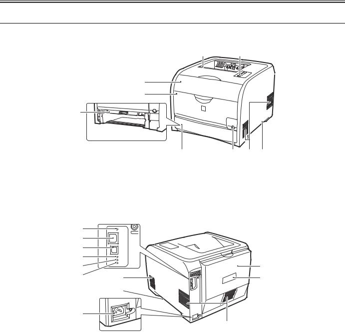
1.4 Name of Parts
1.4.1 External View
[5] |
|
[7] |
[1]
[2]
[3]
[4] |
|
[6] |
|
[8] |
|
[9] |
F-1-1
[1] |
Front Cover |
[6] |
Power Switch |
[2] |
Manual Feed Tray |
[7] |
Control Panel |
[3] Manual Feed Feeding Guide |
[8] |
Delivery Tray |
|
[4] |
Pickup Cassette |
[9] |
Carry Grip |
[5]Delivery Tray
|
[1] |
|
|
|
|
[2] |
|
|
|
|
[3] |
|
|
|
|
[4] |
|
|
|
|
[5] |
|
|
[10] |
|
[6] |
[7] |
|
[11] |
|
|
|
||
|
|
[8] |
|
|
|
[9] |
|
|
|
|
|
|
|
[7] |
|
|
|
|
F-1-2 |
[1] |
|
Reset button |
[7] |
Airway |
[2] |
|
LAN connector |
[8] |
Carry Grip |
[3] |
|
USB connector |
[9] |
Power Code Outlet |
[4] |
|
100 lamp (green) |
[10] |
Rear Cover |
[5] |
|
LNK lamp (green) |
[11] |
Standard rating-plate label |
[6]ERR lamp (orange)
1-3

Chapter 1
1.4.2 Cross Sectional View
[1] |
[2] |
[3] |
[4] |
[5] |
[6] |
[7] |
[17] [16] [15] |
[14] |
[13] |
[12] |
[11] |
[10] |
[9] |
[8] |
|
|
|
|
F-1-3 |
|
|
|
|
|
|
|
T-1-2 |
|
|
|
[1] |
Cross Sectional View |
[10] |
Multi tray feed roller |
[2] |
Pressure roller |
[11] |
Primary transfer pad |
[3] |
Fixing sleeve |
[12] |
ITB Unit |
[4] |
Fixing sleeve |
[13] |
Cassette pickup roller |
[5] |
Cartridge |
[14] |
Cassette separation roller |
[6] |
Laser scanner unit |
[15] |
Registration roller |
[7] |
Photosensitive drum |
[16] |
Secondary transfer roller |
[8] |
Multi tray separation pad |
[17] |
Duplex feed roller (Duplex model) |
[9]Multi tray pickup roller
1-4
Chapter 1
1.5 Using the Machine
1.5.1 Control Panel
 [2]
[2]
[1]
 [3]
[3]
|
|
[4] |
|
|
|
[5] |
|
|
|
[6] |
|
|
|
F-1-4 |
|
Functions of the LEDs |
|
T-1-3 |
|
|
|
||
Name |
Status |
Description |
|
|
Blinking |
Printing cannot be performed because a toner cartridge needs to be replaced, or a toner cartridge is not |
|
[1] Toner Indicator |
installed properly. |
||
|
|||
|
|
||
|
On |
A toner cartridge needs to be replaced. |
|
[2] Paper Source Indicator |
Blinking |
There is no paper or paper of the correct size is not loaded. |
|
[3] Paper Jam Indicator |
Blinking |
A paper jam has occurred and printing cannot be performed. |
|
[4] Alarm Indicator |
Blinking |
An error has occurred and printing cannot be performed. |
|
On |
A service error has occurred. |
||
|
|||
[5] Ready Indicator |
Blinking |
The printer is busy printing, warming up, or cleaning. |
|
On |
The printer is ready to print. |
||
|
|||
[6] Cancel Job Indicator |
Blinking |
A job is being canceled. |
|
On |
The Cancel Job key has been pressed. |
||
|
|||
Functions of the Control Panel Keys |
|
T-1-4 |
|
|
|
||
Name |
|
Function |
|
[6] Cancel Job Key |
Press this key to cancel the job that is currently being printed or a job with an error. |
||
1-5
Chapter 1
1.6 Safety
1.6.1 Safety of the Laser Light
Laser beam radiation may pose a danger to the human body. A laser scanner mounted on the machine is sealed with the protection housing and external cover to prevent the laser beam from leaking to the outside. The laser beam never leaks out of the scanner as far as users operate the machine normally
The following warnings are given to comply with Safety Principles (EN60950).
Laserstrahlen können für den menschlichen Körper gefährlich sein. Aus diesem Grund ist das optische Lasersystem mit einem Schutzgehäuse und einer Außenabdeckung dicht verschlossen und hat eine Struktur, die keine Laserstrahlen nach außen dringen lässt. Unter der Voraussetzung, dass der Benutzer dieses Gerät normal bedient, ist ein Austritt von Laserstrahlen daher ausgeschlossen.
1.6.2 Safety of Toner
1. Toner in General
Toner is a non-toxic material made up of plastic, iron, and small amounts of dye.
Do not throw toner into fire. Doing so can lead to explosion.
2.Contact with Toner
-Toner on the skin or clothes must be removed using dry tissue and then washed with water.
-The use of warm water must be avoided, doing so will cause the toner to turn gel-like and to permanently fuse with the fibers of the clothes.
-Contact with vinyl must also be avoided, as toner can readily react.
3.Store of Copy/Print Output
-Be sure to use transparency cases for storing copy/print output.
Do not use transparency cases made from polyvinyl chloride materials. If the copied surface contacts to the case, toner on the surface of the output dissolves and the output may adhere to the case.
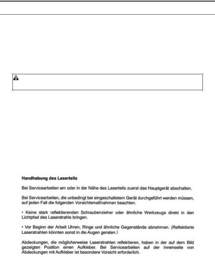
1.6.3 Handling the Laser Unit
When servicing the area around the laser assembly, be sure to turn off the main power. If you must servicr while the power is turned on, be sure to keep the followings:
-Do not use a screwdriver or tools that have a high level of reflectance in the laser path.
-Remove watches and rings before starting the work. (They can reflect the laser beam, possibly hitting the eye.)
The machine's covers that can reflect laser light are identified by means of a warning label (Figure). If you must detach a cover showing the label, be sure to take extra caution during the work.
The following warnings are given to comply with Safety Principles (EN60950).
F-1-5
1-6

Chapter 1
F-1-6
1.6.4 Points to note at disassembly/installation procedure
At disassembly/installation procedure, make sure to follow the instruction below to proceed.
1.Be sure to unplug the power code before disassembly/installation.
2.At installation, follow the procedure in the reverse order of disassembly unless otherwise instructed.
3.Be careful of the screw type (length, diameter) and corresponding part.
4.To check the electrical conductivity, washer equipped screw is used to attach the grounding wire and the varistor etc. When attaching them, be sure to use this screw.
5.In principle, do not operate the machine without any part.
6.Be sure not to unscrew the screw with painting at disassembly.
1-7

Chapter 2 TECHNICAL REFERENCE

Contents
Contents
2.1 Functional Configuration ............................................................................................................................................... |
2-1 |
2.1.1 Outline.......................................................................................................................................................................................... |
2-1 |
2.2 Basic Sequense............................................................................................................................................................... |
2-1 |
2.2.1 Basic Sequence of Operation ....................................................................................................................................................... |
2-1 |
2.3 LASER EXPOSURE SYSTEM..................................................................................................................................... |
2-1 |
2.3.1 Overview/Configuration .............................................................................................................................................................. |
2-1 |
2.3.1.1 Outline............................................................................................................................................................................................................. |
2-1 |
2.3.2 Laser Scanner Motor Control....................................................................................................................................................... |
2-2 |
2.3.2.1 Fault Detection ................................................................................................................................................................................................ |
2-2 |
2.4 IMAGE FORMATION SYSTEM ................................................................................................................................. |
2-2 |
2.4.1 Overview/Configuration .............................................................................................................................................................. |
2-2 |
2.4.1.1 Outline............................................................................................................................................................................................................. |
2-2 |
2.4.1.2 Image-formation Process ................................................................................................................................................................................ |
2-3 |
2.4.1.3 Latent image formation block ......................................................................................................................................................................... |
2-3 |
2.4.1.4 Development block ......................................................................................................................................................................................... |
2-4 |
2.4.1.5 Transfer block ................................................................................................................................................................................................. |
2-4 |
2.4.1.6 Fixing block .................................................................................................................................................................................................... |
2-5 |
2.4.1.7 ITB cleaning block.......................................................................................................................................................................................... |
2-6 |
2.4.1.8 Photosensitive drum cleaning block................................................................................................................................................................ |
2-6 |
2.4.2 High-Voltage Control .................................................................................................................................................................. |
2-7 |
2.4.2.1 Outline............................................................................................................................................................................................................. |
2-7 |
2.4.3 Image Stabilizaton Control .......................................................................................................................................................... |
2-8 |
2.4.3.1 Overview of the Image Stabilization Control Mechanism.............................................................................................................................. |
2-8 |
2.4.3.2 Image density correction control (D-max control).......................................................................................................................................... |
2-8 |
2.4.3.3 Image gradation correction control (D-half control)....................................................................................................................................... |
2-9 |
2.4.3.4 Color displacement correction control ............................................................................................................................................................ |
2-9 |
2.4.4 Drum Cartridge ............................................................................................................................................................................ |
2-9 |
2.4.4.1 Developing roller engagement/disengagement control................................................................................................................................... |
2-9 |
2.4.5 Transfer Unit.............................................................................................................................................................................. |
2-10 |
2.4.5.1 Pad transfer.................................................................................................................................................................................................... |
2-10 |
2.5 Pickup/Feeding/Delivery System................................................................................................................................. |
2-11 |
2.5.1 Overview/Configuration ............................................................................................................................................................ |
2-11 |
2.5.1.1 Overview ....................................................................................................................................................................................................... |
2-11 |
2.5.2 Detecting Jams ........................................................................................................................................................................... |
2-12 |
2.5.2.1 Jam Detection Outline................................................................................................................................................................................... |
2-12 |
2.5.2.1.1 Outline................................................................................................................................................................................................... |
2-12 |
2.5.2.2 Delay Jams .................................................................................................................................................................................................... |
2-12 |
2.5.2.2.1 Pickup delay jam 1 ................................................................................................................................................................................ |
2-12 |
2.5.2.2.2 Pickup delay jam 2 ................................................................................................................................................................................ |
2-12 |
2.5.2.2.3 Fixing delivery delay jam...................................................................................................................................................................... |
2-12 |
2.5.2.3 Stationary Jams ............................................................................................................................................................................................. |
2-12 |
2.5.2.3.1 Pickup stationary jam ............................................................................................................................................................................ |
2-12 |
2.5.2.3.2 Fixing delivery stationary jam .............................................................................................................................................................. |
2-13 |
2.5.2.4 Other Jams..................................................................................................................................................................................................... |
2-13 |
2.5.2.4.1 Fixing wrapping-up jam........................................................................................................................................................................ |
2-13 |
2.5.2.4.2 Inside stationary jam 1 .......................................................................................................................................................................... |
2-13 |
2.5.2.4.3 Inside stationary jam 4 .......................................................................................................................................................................... |
2-13 |
2.5.2.4.4 Duplex re-pickup jam............................................................................................................................................................................ |
2-13 |
2.5.2.4.5 Door open jam....................................................................................................................................................................................... |
2-13 |
2.5.3 Cassette Pickup .......................................................................................................................................................................... |
2-13 |
2.5.3.1 Separation Roller Method ............................................................................................................................................................................. |
2-13 |
2.6 FIXING UNIT SYSTEM............................................................................................................................................. |
2-14 |
2.6.1 Overview/Configuration ............................................................................................................................................................ |
2-14 |

Contents
2.6.1.1 Outline .......................................................................................................................................................................................................... |
2-14 |
2.6.2 Various Control Mechanisms .................................................................................................................................................... |
2-14 |
2.6.2.1 Controlling the Speed of the Fixing Unit...................................................................................................................................................... |
2-14 |
2.6.2.1.1 The speed control of small size paper (throughput down control) ...................................................................................................... |
2-14 |
2.6.2.2 Fixing Temperature Control ......................................................................................................................................................................... |
2-15 |
2.6.2.2.1 Fixing temperature control.................................................................................................................................................................... |
2-15 |
2.6.3 Protective Functions................................................................................................................................................................... |
2-15 |
2.6.3.1 Protective function........................................................................................................................................................................................ |
2-15 |
2.6.3.2 Fixing unit failure detection.......................................................................................................................................................................... |
2-15 |
2.7 EXTERNAL AND CONTROLS SYSTEM ............................................................................................................... |
2-16 |
2.7.1 Power Supply............................................................................................................................................................................. |
2-16 |
2.7.1.1 Power Supply................................................................................................................................................................................................ |
2-16 |
2.7.1.1.1 Low-voltage power supply ................................................................................................................................................................... |
2-16 |
2.7.1.2 Other Function .............................................................................................................................................................................................. |
2-17 |
2.7.1.2.1 Protective function................................................................................................................................................................................ |
2-17 |
2.7.1.2.2 Power-save mode.................................................................................................................................................................................. |
2-17 |
2.8 ENGINE CONTROL SYSTEM ................................................................................................................................. |
2-17 |
2.8.1 Construction............................................................................................................................................................................... |
2-17 |
2.8.1.1 Outline .......................................................................................................................................................................................................... |
2-17 |
2.8.1.2 Motor control ................................................................................................................................................................................................ |
2-18 |
2.8.1.3 Safety ............................................................................................................................................................................................................ |
2-18 |
2.8.2 Main Controller.......................................................................................................................................................................... |
2-18 |
2.8.2.1 Outline .......................................................................................................................................................................................................... |
2-18 |
2.8.2.2 Overview of the Block .................................................................................................................................................................................. |
2-19 |
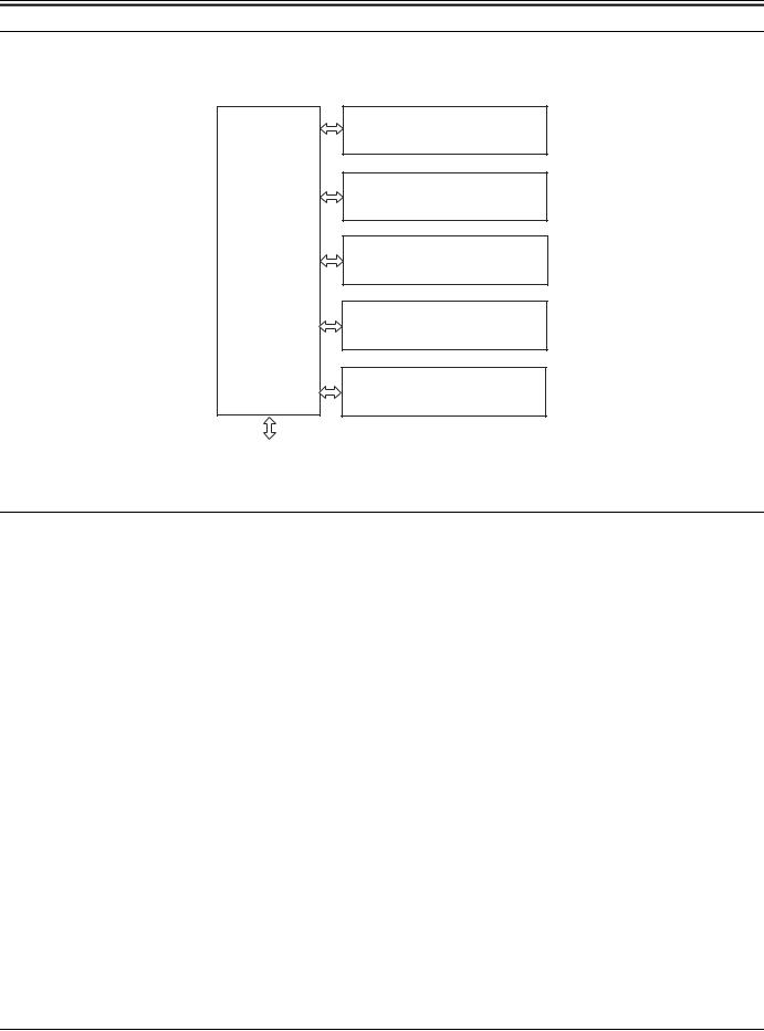
Chapter 2
2.1 Functional Configuration
2.1.1 Outline
The machine may be broadly divided into the following 6 functional blocks: engine control system, laser exposure system, image formation system, pickup/transport/delivery system, fixing system, and externals/auxiliary control system.
Laser exposure system
Image formation system
Pickup/transport/delivery system
Engine control system
Fixing system
Externals and control system
To external device
F-2-1
2.2 Basic Sequense
2.2.1 Basic Sequence of Operation
The operational sequence of the printer is controlled by the DC controller in the engine control system.
Table describes periods, durations and operations for each period of a print operation from the printer is turned on until the motors stop rotating.
T-2-1
Period |
Duration |
Operation |
WAIT |
From the time the power switch is turned on, the door |
Brings the printer to printable condition |
|
is closed or the Sleep mode is released until the |
The printer performs the following during this period: |
|
printer gets ready for a print operation |
- Detects the pressure roller pressurized status |
|
|
- Detects the presence of each cartridge and unit |
|
|
- Determines the homeposition of the development unit |
|
|
- Cleans the ITB |
|
|
- Completes any required calibration, such as color |
|
|
misregistration and image stabilization control |
|
|
|
STBY |
From the end of WAIT or LSTR period until either |
Maintains the printer in printable condition The printer performs the following |
(Standby) |
the print command is received from the main |
during this period: |
|
controller or the power switch is turned off |
- Enters Sleep mode when the main controller sends a sleep command |
|
|
- Completes any required calibration, such as color misregistration control and |
|
|
image stabilization control, when the main controller sends a command |
|
|
|
INTR |
From the time the print command is received from |
Starts up each high-voltage bias, laser scanner unit and fixing unit for preparing a |
(Initial rotation period) |
the main controller during STBY period until the |
print operation |
|
temperature of the fixing unit reaches the targeted |
|
|
temperature |
|
From the end of INTR period until the last media |
Forms the image on the photosensitive drum based on the video signals from the |
|
|
completes the fixing operation |
main controller, transfers and fuses the toner image to the print media The printer |
|
|
performs color misregistration control and image stabilization control at a specified |
|
|
print interval after the printer is turned on |
|
|
|
LSTR |
From the end of PRINT period until the motors stop |
Moves the last printed sheet out of the printer and stops the laser scanner unit |
(Last rotation |
rotating |
operation and high-voltage biases The printer enters INTR period as soon as the |
period) |
|
LSTR period is completed if another print command is received from the main |
|
|
controller |
|
|
|
2.3 LASER EXPOSURE SYSTEM
2.3.1 Overview/Configuration
2.3.1.1 Outline
The laser scanner system forms the latent image on the photosensitive drum according to the VIDEO signals sent from the main controller.
2-1

Chapter 2
The main components of the laser scanner unit are the laser driver and the scanner motor unit and are controlled by the signals sent from the DC controller.
Laser driver PCB
Polygon mirror
Scaner motor unit
BD PCB
Photosensitive drum
(Y)
Photosensitive drum
(M)
Photosensitive drum
(C)
Photosensitive drum (Bk)
DC controller
Main controller
SCANNER MOTOR |
SPEED CONTROL signal |
BD INPUT signal |
LASER CONTROL signal |
VIDEO signal |
|
|
|
|
|
F-2-2
2.3.2 Laser Scanner Motor Control
2.3.2.1 Fault Detection
1.Scanner motor failure
-The scanner motor does not reach a specified rotation within a specified period after starting-up the laser scanner motor.
-The rotation of the scanner motor is out of specified range for a specified period during scanner motor drive.
2.BD failure
-The BD interval is detected at out of a specified value during a print operation.
2.4 IMAGE FORMATION SYSTEM
2.4.1 Overview/Configuration
2.4.1.1 Outline
The image-formation system is the central hub of the printer. It forms the toner image on the media. The following are the main components of the image-formation system:
-Four cartridges
-ITB
-Laser scanner unit
-Fixing unit
The DC controller controls the laser scanner unit and high-voltage power supply to form the toner image on the photosensitive drums according to the VIDEO signals. The image is transferred to the print media through the ITB and fixed.
2-2
Loading...