


 Loading...
Service Manual
LBP3250 Series
LBP3250
Aug 13 2008
Application
This manual has been issued by Canon Inc. for qualified persons to learn technical theory, installation, maintenance, and repair of products. This manual covers all localities where the products are sold. For this reason, there may be information in this manual that does not apply to your locality.
Corrections
This manual may contain technical inaccuracies or typographical errors due to improvements or changes in products. When changes occur in applicable products or in the contents of this manual, Canon will release technical information as the need arises. In the event of major changes in the contents of this manual over a long or short period, Canon will issue a new edition of this manual.
The following paragraph does not apply to any countries where such provisions are inconsistent with local law.
Trademarks
The product names and company names used in this manual are the registered trademarks of the individual companies.
Copyright
This manual is copyrighted with all rights reserved. Under the copyright laws, this manual may not be copied, reproduced or translated into another language, in whole or in part, without the written consent of Canon Inc.
COPYRIGHT © 2001 CANON INC.
Printed in Japan
Caution
Use of this manual should be strictly supervised to avoid disclosure of confidential information.

Introduction
Symbols Used
This documentation uses the following symbols to indicate special information:
Symbol Description
Indicates an item of a non-specific nature, possibly classified as Note, Caution, or Warning.
Indicates an item requiring care to avoid electric shocks.
Indicates an item requiring care to avoid combustion (fire).
Indicates an item prohibiting disassembly to avoid electric shocks or problems.
Indicates an item requiring disconnection of the power plug from the electric outlet.
Indicates an item intended to provide notes assisting the understanding of the topic in question.
Memo
Indicates an item of reference assisting the understanding of the topic in question.
REF.
Provides a description of a service mode.
Provides a description of the nature of an error indication.

Introduction
The following rules apply throughout this Service Manual:
1.Each chapter contains sections explaining the purpose of specific functions and the relationship between electrical and mechanical systems with reference to the timing of operation.
In the diagrams,  represents the path of mechanical drive; where a signal name accompanies the symbol , the arrow
  indicates the
direction of the electric signal.
The expression "turn on the power" means flipping on the power switch, closing the front door, and closing the delivery unit door, which results in supplying the machine with power.
2.In the digital circuits, '1'is used to indicate that the voltage level of a given signal is "High", while '0' is used to indicate "Low".(The voltage value, however, differs from circuit to circuit.) In addition, the asterisk (*) as in "DRMD*" indicates that the DRMD signal goes on when '0'.
In practically all cases, the internal mechanisms of a microprocessor cannot be checked in the field. Therefore, the operations of the microprocessors used in the machines are not discussed: they are explained in terms of from sensors to the input of the DC controller PCB and from the output of the DC controller PCB to the loads.
The descriptions in this Service Manual are subject to change without notice for product improvement or other purposes, and major changes will be communicated in the form of Service Information bulletins.
All service persons are expected to have a good understanding of the contents of this Service Manual and all relevant Service Information bulletins and be able to identify and isolate faults in the machine."

Contents
Contents
Chapter 1 PRODUCT DESCRIPTION |
|
1.1 Features ..................................................................................................................................................... |
1- 1 |
1.1.1 Features .................................................................................................................................................................. |
1- 1 |
1.2 Product Specifications ................................................................................................................................ |
1- 2 |
1.2.1 Specifications .......................................................................................................................................................... |
1- 2 |
1.3 Name of Parts............................................................................................................................................. |
1- 3 |
1.3.1 External View........................................................................................................................................................... |
1- 3 |
1.3.2 Cross Section .......................................................................................................................................................... |
1- 4 |
1.4 Using the Machine...................................................................................................................................... |
1- 5 |
1.4.1 Control Panel........................................................................................................................................................... |
1- 5 |
1.5 Safety ......................................................................................................................................................... |
1- 5 |
1.5.1 Safety of Laser Light................................................................................................................................................ |
1- 5 |
1.5.2 CDRH Regulations .................................................................................................................................................. |
1- 5 |
1.5.3 Safety of Toner ........................................................................................................................................................ |
1- 6 |
1.5.4 Handling the Laser Unit ........................................................................................................................................... |
1- 6 |
1.5.5 Points to Note at Disassembly/Assembly Work....................................................................................................... |
1- 6 |
Chapter 2 TECHNICAL REFERENCE |
|
2.1 Functional Configuration............................................................................................................................. |
2- 1 |
2.1.1 Outline ..................................................................................................................................................................... |
2- 1 |
2.2 Basic Sequence.......................................................................................................................................... |
2- 1 |
2.2.1 Basic Sequence of Operation.................................................................................................................................. |
2- 1 |
2.2.2 Power-On Sequence ............................................................................................................................................... |
2- 2 |
2.3 LASER EXPOSURE SYSTEM ................................................................................................................... |
2- 3 |
2.3.1 Overview/Configuration ........................................................................................................................................... |
2- 3 |
2.3.1.1 Overview .................................................................................................................................................................................. |
2- 3 |
2.3.2 Controlling the Laser Activation Timing ................................................................................................................... |
2- 4 |
2.3.2.1 Laser ON/OFF Control............................................................................................................................................................. |
2- 4 |
2.3.2.2 Horizontal Sync Control ........................................................................................................................................................... |
2- 4 |
2.3.3 Laser Control ........................................................................................................................................................... |
2- 5 |
2.3.3.1 Auto Power Control (APC) ....................................................................................................................................................... |
2- 5 |
2.3.4 Laser Scanner Motor Control .................................................................................................................................. |
2- 5 |
2.3.4.1 Overview .................................................................................................................................................................................. |
2- 5 |
2.3.4.2 Scanner Motor Fault Detection ................................................................................................................................................ |
2- 6 |
2.4 IMAGE FORMATION SYSTEM.................................................................................................................. |
2- 7 |
2.4.1 Overview/Configuration ........................................................................................................................................... |
2- 7 |
2.4.1.1 Overview .................................................................................................................................................................................. |
2- 7 |
2.4.1.2 Print Process............................................................................................................................................................................ |
2- 8 |
2.4.1.3 Static Latent Image Formation Block ....................................................................................................................................... |
2- 9 |
2.4.1.4 Development Block ................................................................................................................................................................ |
2- 10 |
2.4.1.5 Transfer Block........................................................................................................................................................................ |
2- 11 |
2.4.1.6 Fixing Block............................................................................................................................................................................ |
2- 12 |
2.4.1.7 Drum Cleaning Block ............................................................................................................................................................. |
2- 12 |
2.4.2 High-Voltage Control ............................................................................................................................................. |
2- 13 |
2.4.2.1 Overview ................................................................................................................................................................................ |
2- 13 |
2.4.2.2 Generating Primary Charging Bias ........................................................................................................................................ |
2- 13 |
2.4.2.3 Generating Developing Bias .................................................................................................................................................. |
2- 13 |
2.4.2.4 Generating Transfer Bias....................................................................................................................................................... |
2- 13 |
2.4.3 Toner Cartridge ..................................................................................................................................................... |
2- 14 |
2.4.3.1 |
Toner Level Detection............................................................................................................................................................ |
2- 14 |
2.4.3.2 |
Toner Cartridge Absence/Presence Detection ...................................................................................................................... |
2- 14 |

Contents
2.5 PICKUP AND FEEDING SYSTEM........................................................................................................... |
2- 15 |
2.5.1 Overview/Configuration.......................................................................................................................................... |
2- 15 |
2.5.1.1 Overview ................................................................................................................................................................................ |
2- 15 |
2.5.2 Detecting Jams ...................................................................................................................................................... |
2- 16 |
2.5.2.1 Jam Detection Outline............................................................................................................................................................ |
2- 16 |
2.5.2.2 Delay Jams ............................................................................................................................................................................ |
2- 17 |
2.5.2.3 Stationary Jams ..................................................................................................................................................................... |
2- 17 |
2.5.2.4 Other Jams ............................................................................................................................................................................ |
2- 17 |
2.6 EXTERNAL AND CONTROLS SYSTEM ................................................................................................. |
2- 18 |
2.6.1 Power Supply......................................................................................................................................................... |
2- 18 |
2.6.1.1 Power Supply......................................................................................................................................................................... |
2- 18 |
2.6.1.2 Protective Functions .............................................................................................................................................................. |
2- 19 |
2.7 ENGINE CONTROL SYSTEM ................................................................................................................. |
2- 20 |
2.7.1 Main Controller....................................................................................................................................................... |
2- 20 |
2.7.1.1 General description................................................................................................................................................................ |
2- 20 |
2.7.2 Engine Controller ................................................................................................................................................... |
2- 21 |
2.7.2.1 General description................................................................................................................................................................ |
2- 21 |
2.8 FIXING UNIT/DELIVERY SYSTEM.......................................................................................................... |
2- 22 |
2.8.1 Overview/Configuration.......................................................................................................................................... |
2- 22 |
2.8.1.1 Overview ................................................................................................................................................................................ |
2- 22 |
2.8.1.2 Main Parts of Fixing Unit........................................................................................................................................................ |
2- 22 |
2.8.2 Various Control Mechanisms................................................................................................................................. |
2- 23 |
2.8.2.1 Fixing Temperature Control ................................................................................................................................................... |
2- 23 |
2.8.2.2 Protective Functions .............................................................................................................................................................. |
2- 24 |
2.8.3 Other Functions ..................................................................................................................................................... |
2- 25 |
2.8.3.1 Throughput Down Control...................................................................................................................................................... |
2- 25 |
Chapter 3 DISASSEMBLY AND ASSEMBLY |
|
3.1 EXTERNAL AND CONTROLS SYSTEM ................................................................................................... |
3- 1 |
3.1.1 Rear Cover............................................................................................................................................................... |
3- 1 |
3.1.1.1 Before Removing the Rear Cover............................................................................................................................................ |
3- 1 |
3.1.1.2 Removing the Rear Cover ....................................................................................................................................................... |
3- 1 |
3.1.2 Right Cover .............................................................................................................................................................. |
3- 1 |
3.1.2.1 Before Removing the Right Cover ........................................................................................................................................... |
3- 1 |
3.1.2.2 Removing the Right Cover....................................................................................................................................................... |
3- 1 |
3.1.3 Left Cover ................................................................................................................................................................ |
3- 1 |
3.1.3.1 Before Removing the Left Cover.............................................................................................................................................. |
3- 1 |
3.1.3.2 Removing the Left Cover ......................................................................................................................................................... |
3- 1 |
3.1.4 Upper Cover............................................................................................................................................................. |
3- 2 |
3.1.4.1 Removing the Upper Cover ..................................................................................................................................................... |
3- 2 |
3.1.5 Front Cover .............................................................................................................................................................. |
3- 3 |
3.1.5.1 Before Removing the Front Cover ........................................................................................................................................... |
3- 3 |
3.1.5.2 Removing the Front Cover....................................................................................................................................................... |
3- 3 |
3.1.6 Delivery Tray............................................................................................................................................................ |
3- 3 |
3.1.6.1 Removing the Delivery Auxiliary Tray ...................................................................................................................................... |
3- 3 |
3.1.7 Pickup Tray .............................................................................................................................................................. |
3- 3 |
3.1.7.1 Before Removing the Pickup Tray ........................................................................................................................................... |
3- 3 |
3.1.7.2 Removing the Pickup Tray Unit ............................................................................................................................................... |
3- 3 |
3.1.8 Drive Unit ................................................................................................................................................................. |
3- 4 |
3.1.8.1 Before Removing the Drive Belt............................................................................................................................................... |
3- 4 |
3.1.8.2 Removing the Drive Belt .......................................................................................................................................................... |
3- 4 |
3.1.9 Main Drive Unit ........................................................................................................................................................ |
3- 5 |
3.1.9.1 Before Removing the Main Motor ............................................................................................................................................ |
3- 5 |
3.1.9.2 Removing the Main Motor........................................................................................................................................................ |
3- 5 |
3.1.10 Engine controller board .......................................................................................................................................... |
3- 7 |
3.1.10.1 Before Removing the Engine Controller PCB ........................................................................................................................ |
3- 7 |
3.1.10.2 Removing the Engine Controller PCB.................................................................................................................................... |
3- 7 |
3.1.11 Main Controller PCB .............................................................................................................................................. |
3- 8 |
|
Contents |
|
|
|
|
3.1.11.1 Before Removing the Main Controller PCB............................................................................................................................ |
3- 8 |
3.1.11.2 Removing the Main Controller PCB ....................................................................................................................................... |
3- 8 |
3.1.12 Top sensor............................................................................................................................................................. |
3- 8 |
3.1.12.1 Before Removing the Paper Lead Edge Sensor .................................................................................................................... |
3- 8 |
3.1.12.2 Removing the Paper Lead Edge Sensor................................................................................................................................ |
3- 8 |
3.1.13 Sensor Boade ........................................................................................................................................................ |
3- 9 |
3.1.13.1 Before Removing the Sensor PCB......................................................................................................................................... |
3- 9 |
3.1.13.2 Removing the Sensor PCB .................................................................................................................................................... |
3- 9 |
3.2 LASER EXPOSURE SYSTEM ................................................................................................................. |
3- 10 |
3.2.1 Laser Scanner Unit................................................................................................................................................ |
3- 10 |
3.2.1.1 Before Removing the Laser Scanner Unit ............................................................................................................................. |
3- 10 |
3.2.1.2 Removing the Laser Scanner Unit ......................................................................................................................................... |
3- 10 |
3.3 IMAGE FORMATION SYSTEM................................................................................................................ |
3- 11 |
3.3.1 Transfer Charging Roller ....................................................................................................................................... |
3- 11 |
3.3.1.1 Removing the Transfer Roller ................................................................................................................................................ |
3- 11 |
3.3.2 Memory Tag Contact Unit...................................................................................................................................... |
3- 12 |
3.3.2.1 Before Removing the Memory Contact Unit .......................................................................................................................... |
3- 12 |
3.3.2.2 Removing the Memory Contact Unit ...................................................................................................................................... |
3- 12 |
3.4 PICKUP AND FEEDING SYSTEM........................................................................................................... |
3- 14 |
3.4.1 Pickup Unit ............................................................................................................................................................ |
3- 14 |
3.4.1.1 Before Removing the Pickup Unit .......................................................................................................................................... |
3- 14 |
3.4.1.2 Removing the Pickup Unit...................................................................................................................................................... |
3- 14 |
3.4.2 Cassette Pickup Roller .......................................................................................................................................... |
3- 15 |
3.4.2.1 Removing the Pickup Roller................................................................................................................................................... |
3- 15 |
3.4.3 Cassette Pickup solenoid ...................................................................................................................................... |
3- 15 |
3.4.3.1 Before Removing the Pickup Solenoid .................................................................................................................................. |
3- 15 |
3.4.3.2 Removing the Pickup Solenoid .............................................................................................................................................. |
3- 16 |
3.4.4 Cassette Separation Pad....................................................................................................................................... |
3- 16 |
3.4.4.1 Removing the Separation Pad ............................................................................................................................................... |
3- 16 |
3.5 FIXING SYSTEM...................................................................................................................................... |
3- 16 |
3.5.1 Fixing Unit.............................................................................................................................................................. |
3- 16 |
3.5.1.1 Before Removing the Fixing Unit ........................................................................................................................................... |
3- 16 |
3.5.1.2 Removing the Fixing Unit....................................................................................................................................................... |
3- 16 |
3.5.2 Fixing Film Unit...................................................................................................................................................... |
3- 17 |
3.5.2.1 Before Removing the Fixing Film Unit ................................................................................................................................... |
3- 17 |
3.5.2.2 Removing the Fixing Film Unit ............................................................................................................................................... |
3- 17 |
3.5.3 Fixing Pressure Roller ........................................................................................................................................... |
3- 18 |
3.5.3.1 Before Removing the Fixing Pressure Roller......................................................................................................................... |
3- 18 |
3.5.3.2 Removing the Fixing Pressure Roller .................................................................................................................................... |
3- 18 |
Chapter 4 MAINTENANCE AND INSPECTION |
|
4.1 Periodically Replaced Parts........................................................................................................................ |
4- 1 |
4.1.1 Periodically Replaced Parts..................................................................................................................................... |
4- 1 |
4.2 Consumables.............................................................................................................................................. |
4- 1 |
4.2.1 Consumables........................................................................................................................................................... |
4- 1 |
4.3 Periodical Service....................................................................................................................................... |
4- 1 |
4.3.1 Scheduled Servicing................................................................................................................................................ |
4- 1 |
4.4 Cleaning ..................................................................................................................................................... |
4- 2 |
4.4.1 Cleaning Method ..................................................................................................................................................... |
4- 2 |
Chapter 5 TROUBLESHOOTING |
|
5.1 MEASUREMENT AND ADJUSTMENT...................................................................................................... |
5- 1 |
5.1.1 Test Print ................................................................................................................................................................. |
5- 1 |
5.1.1.1 Test Print Function................................................................................................................................................................... |
5- 1 |
5.1.2 Mechanical Adjustment ........................................................................................................................................... |
5- 1 |
5.1.2.1 Checking the Pressure of the Pressure Roller (nip)................................................................................................................. |
5- 1 |

Contents
5.2 SERVICE TOOLS ...................................................................................................................................... |
5- 2 |
5.2.1 Standard tools.......................................................................................................................................................... |
5- 2 |
5.2.2 Special Tool ............................................................................................................................................................. |
5- 2 |
5.2.3 List of solvent/ lubricant ........................................................................................................................................... |
5- 2 |
5.3 ERROR CODE TABLE............................................................................................................................... |
5- 3 |
5.3.1 Overview .................................................................................................................................................................. |
5- 3 |
5.3.2 Service Message ..................................................................................................................................................... |
5- 4 |
5.4 Version Up.................................................................................................................................................. |
5- 4 |
5.4.1 Upgrade ................................................................................................................................................................... |
5- 4 |
Chapter 6 APPENDIX |
|
6.1 OUTLINE OF ELECTRICAL COMPONENTS............................................................................................ |
6- 1 |
6.1.1 Clutch/Solenoid........................................................................................................................................................ |
6- 1 |
6.1.1.1 Solenoid ................................................................................................................................................................................... |
6- 1 |
6.1.2 Motor........................................................................................................................................................................ |
6- 1 |
6.1.2.1 Motor........................................................................................................................................................................................ |
6- 1 |
6.1.3 Sensor...................................................................................................................................................................... |
6- 2 |
6.1.3.1 Sensor...................................................................................................................................................................................... |
6- 2 |
6.1.4 Switch ...................................................................................................................................................................... |
6- 2 |
6.1.4.1 Switch ...................................................................................................................................................................................... |
6- 2 |
6.1.5 PCBs........................................................................................................................................................................ |
6- 3 |
6.1.5.1 PCB.......................................................................................................................................................................................... |
6- 3 |

Chapter 1 PRODUCT DESCRIPTION

Contents
Contents
1.1 |
Features .......................................................................................................................................................................... |
1-1 |
1.1.1 Features ........................................................................................................................................................................................ |
1-1 |
|
1.2 |
Product Specifications.................................................................................................................................................... |
1-2 |
1.2.1 Specifications............................................................................................................................................................................... |
1-2 |
|
1.3 |
Name of Parts................................................................................................................................................................. |
1-3 |
1.3.1 External View .............................................................................................................................................................................. |
1-3 |
|
1.3.2 Cross Section ............................................................................................................................................................................... |
1-4 |
|
1.4 |
Using the Machine ......................................................................................................................................................... |
1-5 |
1.4.1 Control Panel ............................................................................................................................................................................... |
1-5 |
|
1.5 |
Safety ............................................................................................................................................................................. |
1-5 |
1.5.1 Safety of Laser Light ................................................................................................................................................................... |
1-5 |
|
1.5.2 CDRH Regulations ...................................................................................................................................................................... |
1-5 |
|
1.5.3 Safety of Toner ............................................................................................................................................................................ |
1-6 |
|
1.5.4 Handling the Laser Unit............................................................................................................................................................... |
1-6 |
|
1.5.5 Points to Note at Disassembly/Assembly Work .......................................................................................................................... |
1-6 |
|
Chapter 1
1.1 Features
1.1.1 Features
1. Small-size, high-speed monochrome printer
This equipment has a compact body that realizes high-speed print of 23 ppm.
2. Reduction in standby time and energy consumption
This equipment employs on-demand fixing where the heater activates only during printing, resulting in a reduction in standby time and energy consumption on this mode.
3. Realization of noise reduction and stable image quality
This equipment employs a belt drive method for transmitting the drive of the main motor. This enables lower noise and more stable image quality compared to the conventional gear drive method. (See MEMO)
4.Improved Usability
In this equipment, the power switch is situated at the front of the host machine, and maintenance (jam removal, replacing the cartridge) can be performed by accessing one point of the delivery tray.
MEMO:
Changing the drive method from gear to belt reduces uneven pitch due to varied rotation speed of the photosensitive drum, which realizes stable image quality.
1-1

Chapter 1
1.2 Product Specifications
1.2.1 Specifications
Body installation method |
desktop page printer |
Photosensitive medium |
OPC drum |
Exposure method |
semiconductor laser |
|
|
Development method |
Toner projection development |
|
|
Transfer method |
by roller |
Separation method |
Curvature |
|
|
Pickup-tray pickup method |
by pad |
Multifeeder pickup method |
by pad |
|
|
Drum cleaning method |
by blade |
|
|
Fixing method |
on-demand |
Delivery method |
face-down |
|
|
Toner supply type |
By toner cartridge |
|
|
Warm-up time |
in standby: 0 sec (at power-on: 10 sec or less) |
Print area |
top: 5 mm; bottom: 5 mm; left/right: 5 mm (if envelope, top, bottom, left, |
|
right: 10 mm) |
|
|
Printing resolution |
600dpi |
First print time |
approx. 6 sec or less (A4) |
|
|
Print speed (A4) |
approx. 23ppm |
|
|
Pickup-tray paper size |
A4, B5, A5, LGL, LTR, Executive,16K, Envelope(DL,COM10,C5, |
|
Monarch), user-defined paper (76.2 to 215.9 mm in width, 127 to 355.6 |
|
mm in length) |
|
|
Multi-purpose paper size |
A4, B5, A5, LGL, LTR, Executive,16K, Envelope(DL,COM10,C5, |
|
Monarch), user-defined paper (76.2 to 215.9 mm in width, 127 to 355.6 |
|
mm in length) |
|
|
Pickup-tray paper type |
plain paper (60 to 105 g/m2), heavy paper (106 to 163 g/m2), |
|
transparency, label sheet, postcard |
|
|
Pickup-tray paper capacity |
Approx. 250 sheets (plain paper 64 g/m2) |
Multi-purpose capacity |
1 sheet (plain paper 64 g/m2) |
|
|
Delivery tray stack |
Approx. 100 sheets (plain paper 64 g/m2) |
|
|
Duplex method |
None |
Hard disk |
Standard: none, Option: none |
|
|
Interface |
USB 2.0, Option: none |
|
|
Memory |
Standard: 2MB, Option: none |
Operating environment |
7.5 deg C to 32.5 deg C |
(Temperature range) |
|
|
|
Operating environment |
10 to 80%RH |
(Humidity range) |
|
|
|
Noise |
55 dB or less (during printing; based on ISO9296; announced noise |
|
emission) |
|
|
Power supply rating |
AC120-127V, +/-10% (50,60Hz +/-2Hz) |
|
AC220-240V, +/-10% (50,60Hz +/-2Hz) |
|
|
Power consumption (Maximum) |
AC120-127V: |
|
Approx.830W more less (The value of the reference room temperature at |
|
20 deg C) |
|
AC220-240V: |
|
Approx.990W more less (The value of the reference room temperature at |
|
20 deg C) |
|
|
Dimensions |
384 (W) x 258 (D) x 227 (H) mm |
Weight |
Printer: Approx. 6.4kg, Toner cartridge: Approx. 0.6kg |
|
|
1-2
Chapter 1
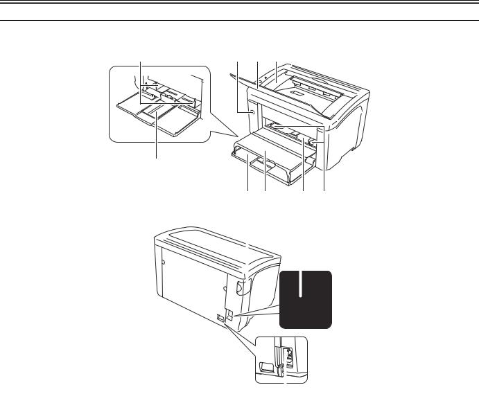
1.3 Name of Parts
1.3.1 External View
[9] |
[8]
[1][2] [3]
[7] |
[6] |
[5] |
[4] |
[10] |
[11] |
|
|
|
|
|
|
|
|
|
|
|
|
|
|
|
|
|
|
|
|
|
|
|
[12] |
|
|
||
|
|
|
|
|||
|
F-1-1 |
|||||
[1] Power switch |
[2] Delivery auxiliary tray |
|||||
[3] Delivery tray |
[4] Manual feed tray paper guide |
|||||
[5] Manual feed tray |
[6] Tray cover |
|||||
[7] Pickup tray |
[8] Rear paper guide |
|||||
[9] Pickup tray Paper guide |
[10] USB cover |
|||||
[11] USB connector |
[12] Power receptacle |
|||||
1-3

Chapter 1
1.3.2 Cross Section
[1] |
[2] |
[3] |
[4] |
[5] |
[6]
[13] |
|
[12] |
|
[11] |
|
[10] |
|
[9] |
|
[8] |
[1] Fixing unit
[3] Fixing sleeve unit [5] Laser scanner unit [7] Pickup tray
[9] Pickup roller [11] Feed roller [13] Toner cartridge
[7]
F-1-2
[2]Pressure roller
[4]Delivery roller
[6]Manual feed tray
[8]Photosensitive drum
[10]separation pad
[12]Transfer roller
1-4

Chapter 1
1.4 Using the Machine
1.4.1 Control Panel
[1]
[2]

F-1-3
[1]Power lamp (green)
Lighting:
Indicates that the power of the host machine is turned on. Not lighting:
Indicates that the power of the host machine is not turned on.
[2]Paper lamp/paper key (red)
<Lamp>
Flashing:
Indicates that there is no paper in the pickup source and print cannot be executed, or papers cannot be fed correctly. Not lighting:
Indicates that the machine can make prints.
<Key>
Pressing this key after executing pickup of paper or jam removal restarts printing.
1.5 Safety
1.5.1 Safety of Laser Light
Laser light can be extremely hazardous to the human body.
The machines laser scanning system is contained in a protective housing and external covers to prevent escape of laser light outside the machine. In other words, the user is free of laser-related hazards as long as the machine is being used for its intended purposes.
The following warnings are given to comply with Safety Principles (EN60950).
Laserstrahlen können für den menschlichen Körper gefährlich sein. Aus diesem Grund ist das optische Lasersystem mit einem Schutzgehäuse und einer Außenabdeckung dicht verschlossen und hat eine Struktur, die keine Laserstrahlen nach außen dringen lässt. Unter der Voraussetzung, dass der Benutzer dieses Gerät normal bedient, ist ein Austritt von Laserstrahlen daher ausgeschlossen.
1.5.2 CDRH Regulations
The Center for Devices and Radiological Health of the US Food and Drug Administration put into effect regulations concerning laser products on August 2, 1976. These regulations apply to products produced on and after August 1, 1976, and prohibit the sale of laser products without certification. The following is a label used to certify compliance with the CDRH regulations, and all laser products to be sold in the US must bear this label.
F-1-4
1-5

Chapter 1
1.5.3 Safety of Toner
The machines toner is a non-toxic material made up of plastic, iron, and small amounts of dye.
Do not throw toner into fire. Doing so can lead to explosion.
Toner on Clothing or Skin
1.Remove toner from clothing or skin, and wash with water.
2.Do not use warm or hot water, which will cause the toner to turn jelly-like and fuse permanently with the fibers of clothing.
3.Toner tends to react readily with vinyl. Do not bring it in contact.
4.Storage of copy/print output
Do not use the polyvinyl case.
If printed side contacts with the surface of case, toner melts and the paper may be adhered with a case.
1.5.4 Handling the Laser Unit
The laser scanner unit emits invisible laser beam. DO NOT disassemble the unit as the laser beam can possibly damage your eyes. The unit cannot be adjusted in the field. The following label is attached to the cover of the unit:
F-1-5
1.5.5 Points to Note at Disassembly/Assembly Work
Be sure to ensure the following notes when performing disassembly/assembly work.
1.Be sure to disconnect the power plug for safety when performing disassembly/assembly work.
2.As for assembly procedure, perform the reverse procedure of disassembly unless otherwise instructed.
3.Avoid making mistakes in the type of screws (length/diameter) and usage locations for assembly.
4.Screws w/washer are used as mounting screws for grounding wires and varistors with the aim of checking electric continuity. Be sure to use this screw for assembly.
5.Basically, do not activate the machine with their parts being removed.
6.Do not remove paintlock screws at the time of disassembly.
1-6

Chapter 2 TECHNICAL REFERENCE

Contents
Contents
2.1 Functional Configuration ............................................................................................................................................... |
2-1 |
2.1.1 Outline.......................................................................................................................................................................................... |
2-1 |
2.2 Basic Sequence .............................................................................................................................................................. |
2-1 |
2.2.1 Basic Sequence of Operation ....................................................................................................................................................... |
2-1 |
2.2.2 Power-On Sequence..................................................................................................................................................................... |
2-2 |
2.3 LASER EXPOSURE SYSTEM..................................................................................................................................... |
2-3 |
2.3.1 Overview/Configuration .............................................................................................................................................................. |
2-3 |
2.3.1.1 Overview ......................................................................................................................................................................................................... |
2-3 |
2.3.2 Controlling the Laser Activation Timing..................................................................................................................................... |
2-4 |
2.3.2.1 Laser ON/OFF Control ................................................................................................................................................................................... |
2-4 |
2.3.2.2 Horizontal Sync Control ................................................................................................................................................................................. |
2-4 |
2.3.3 Laser Control ............................................................................................................................................................................... |
2-5 |
2.3.3.1 Auto Power Control (APC)............................................................................................................................................................................. |
2-5 |
2.3.4 Laser Scanner Motor Control....................................................................................................................................................... |
2-5 |
2.3.4.1 Overview ......................................................................................................................................................................................................... |
2-5 |
2.3.4.2 Scanner Motor Fault Detection ....................................................................................................................................................................... |
2-6 |
2.4 IMAGE FORMATION SYSTEM ................................................................................................................................. |
2-7 |
2.4.1 Overview/Configuration .............................................................................................................................................................. |
2-7 |
2.4.1.1 Overview ......................................................................................................................................................................................................... |
2-7 |
2.4.1.2 Print Process.................................................................................................................................................................................................... |
2-8 |
2.4.1.3 Static Latent Image Formation Block ............................................................................................................................................................. |
2-9 |
2.4.1.4 Development Block....................................................................................................................................................................................... |
2-10 |
2.4.1.5 Transfer Block............................................................................................................................................................................................... |
2-11 |
2.4.1.6 Fixing Block.................................................................................................................................................................................................. |
2-12 |
2.4.1.7 Drum Cleaning Block ................................................................................................................................................................................... |
2-12 |
2.4.2 High-Voltage Control ................................................................................................................................................................ |
2-13 |
2.4.2.1 Overview ....................................................................................................................................................................................................... |
2-13 |
2.4.2.2 Generating Primary Charging Bias ............................................................................................................................................................... |
2-13 |
2.4.2.3 Generating Developing Bias ......................................................................................................................................................................... |
2-13 |
2.4.2.4 Generating Transfer Bias .............................................................................................................................................................................. |
2-13 |
2.4.3 Toner Cartridge.......................................................................................................................................................................... |
2-14 |
2.4.3.1 Toner Level Detection................................................................................................................................................................................... |
2-14 |
2.4.3.2 Toner Cartridge Absence/Presence Detection .............................................................................................................................................. |
2-14 |
2.5 PICKUP AND FEEDING SYSTEM........................................................................................................................... |
2-15 |
2.5.1 Overview/Configuration ............................................................................................................................................................ |
2-15 |
2.5.1.1 Overview ....................................................................................................................................................................................................... |
2-15 |
2.5.2 Detecting Jams ........................................................................................................................................................................... |
2-16 |
2.5.2.1 Jam Detection Outline................................................................................................................................................................................... |
2-16 |
2.5.2.1.1 Overview ............................................................................................................................................................................................... |
2-16 |
2.5.2.2 Delay Jams .................................................................................................................................................................................................... |
2-17 |
2.5.2.2.1 Delivery Delay Jam............................................................................................................................................................................... |
2-17 |
2.5.2.3 Stationary Jams ............................................................................................................................................................................................. |
2-17 |
2.5.2.3.1 Pickup Stationary Jam........................................................................................................................................................................... |
2-17 |
2.5.2.3.2 Delivery Stationary Jam........................................................................................................................................................................ |
2-17 |
2.5.2.4 Other Jams..................................................................................................................................................................................................... |
2-17 |
2.5.2.4.1 Fixing Take-up Jam............................................................................................................................................................................... |
2-17 |
2.5.2.4.2 Remaining Jam at Start-up .................................................................................................................................................................... |
2-17 |
2.6 EXTERNAL AND CONTROLS SYSTEM ................................................................................................................ |
2-18 |
2.6.1 Power Supply ............................................................................................................................................................................. |
2-18 |
2.6.1.1 Power Supply ................................................................................................................................................................................................ |
2-18 |
2.6.1.1.1 Low voltage power circuit..................................................................................................................................................................... |
2-18 |
2.6.1.2 Protective Functions...................................................................................................................................................................................... |
2-19 |
2.6.1.2.1 Power protective function ..................................................................................................................................................................... |
2-19 |

Contents
2.6.1.2.2 Safety function...................................................................................................................................................................................... |
2-19 |
2.7 ENGINE CONTROL SYSTEM ................................................................................................................................. |
2-20 |
2.7.1 Main Controller.......................................................................................................................................................................... |
2-20 |
2.7.1.1 General description ....................................................................................................................................................................................... |
2-20 |
2.7.2 Engine Controller....................................................................................................................................................................... |
2-21 |
2.7.2.1 General description ....................................................................................................................................................................................... |
2-21 |
2.8 FIXING UNIT/DELIVERY SYSTEM ....................................................................................................................... |
2-22 |
2.8.1 Overview/Configuration ............................................................................................................................................................ |
2-22 |
2.8.1.1 Overview....................................................................................................................................................................................................... |
2-22 |
2.8.1.2 Main Parts of Fixing Unit ............................................................................................................................................................................. |
2-22 |
2.8.2 Various Control Mechanisms .................................................................................................................................................... |
2-23 |
2.8.2.1 Fixing Temperature Control ......................................................................................................................................................................... |
2-23 |
2.8.2.1.1 Fixing Temperature Control ................................................................................................................................................................. |
2-23 |
2.8.2.2 Protective Functions ..................................................................................................................................................................................... |
2-24 |
2.8.2.2.1 Protective Function of Fixing Unit ....................................................................................................................................................... |
2-24 |
2.8.2.2.2 Error detection ...................................................................................................................................................................................... |
2-24 |
2.8.3 Other Functions.......................................................................................................................................................................... |
2-25 |
2.8.3.1 Throughput Down Control............................................................................................................................................................................ |
2-25 |
Chapter 2
2.1 Functional Configuration
2.1.1 Outline
The machine may be broadly divided into the following 6 functional blocks: engine control system, laser exposure system, image formation system, pickup/transport/delivery system, fixing system, and externals/auxiliary control system.
Laser exposure system
Image formation system
Pickup/transport/delivery system
Engine control system
Fixing system
Externals and control system
External device
F-2-1
2.2 Basic Sequence
2.2.1 Basic Sequence of Operation
The engine controller controls the operation sequence. The following table provides an outline of machine operation occurring from when the power switch is turned on to when printing ends and motors stop, indicating the purposes of intervals and engine operation. For details of various loads, see the timing chart.
T-2-1
|
Interval |
Purpose |
Remarks |
WAIT |
From power-ON until initial drive for main |
To clear potential from the drum surface and to |
Detect whether the Toner cartridge is installed or |
(Wait) |
motor is completed. |
clean the transfer roller. |
not. |
|
|
Also to bring the heater temperature up to the |
|
|
|
targeted temperature. |
|
|
|
|
|
STBY |
From the end of the WAIT period or the LSTR |
To keep the printer ready to print. |
|
(Standby) |
period until the print command is sent from the |
|
|
|
main controller. Or, from the end of the LSTR |
|
|
|
period until power switch is turned OFF. |
|
|
|
|
|
|
INTR |
From the input of the print command from the |
To stabilize the photosensitive drum sensitivity |
|
(initial |
main controller until the pick-up solenoid is |
in preparation for printing. Also to clean the |
|
rotation) |
turned ON. |
transfer roller. |
|
|
|
|
|
From the end of the INTR period until the top of |
To form image on the photosensitive drum based |
|
|
(print) |
page sensor detects the trailing edge of paper. |
on the VIDEO (/VD01, /VD02, VD01, VD02) |
|
|
|
signals input from the main controller, and to |
|
|
|
transfer the toner image onto paper. |
|
LSTR |
From the end of PRINT period until the Main |
To deliver the last paper completely out of the |
Return to the INTR period as soon as another |
(last rotation) |
motor stops. |
printer. |
print command is sent from the main controller. |
|
|
|
|
2-1
Chapter 2
2.2.2 Power-On Sequence
The sequences from the power-ON to the STBY period are described below.
1)Power-ON
2)CPU initialization
3)Video interface communication start
4)Residual paper check
Detecting paper presence by each sensor signaling.
5)Initial drive for main motor
6)Initial drive for fixing heater
Controlling fixing temperature targeting for 120 deg C.
7)Initial drive of the scanner motor.
8)High-voltage control
Detect cartridge presence after primary charging AC bias is applied. Cleaning transfer roller.
9) Failure/Abnormality check
Detecting fixing unit failure and door open during above periods.
2-2
Chapter 2
2.3 LASER EXPOSURE SYSTEM
2.3.1 Overview/Configuration
2.3.1.1 Overview
The laser exposure system forms static latent images on the photosensitive drum according to the VIDEO signals sent from the main controller, and is comprised of the laser driver and scanner motor, etc. There are controlled by the engine controller. The following is the outline.
Photosensitive drum
BD sensor
Cylindrical lens
Laser unit
Collimator
lens
BD INPUT signal |
VIDEO signal |
LASER CONTROL signal |
SCANNER MOTOR SPEED CONTROL signal
Focus lens
Scanner motor unit Four-faced mirror
Engine Controller
Main controller
F-2-2
The operational sequence of the laser scanner unit is described below.
1)When the Main controller sends print instruction command, the Engine controller rotates the Four-faced mirror, causing the Scanner motor to rotate.
2)When the Scanner motor starts to rotate, the Engine controller emits the laser forcibly using the Laser control signal, causing the Engine controller to start rotation control for the Scanner motor.
3)The Engine controller controls to keep a constant speed of rotation of the Scanner motor using the Scanner motor speed control signal.
4)After the rotation speed of the Scanner motor reaches its target, the Main controller sends VIDEO signals to the Laser driver PCB.
5)The Laser driver emits laser diode according to these signals.
6)The laser beam passes through the collimator lens and the cylindrical lens and enters the Four-faced mirror rotating at a constant speed.
7)The laser beam reflected by the Four-faced mirror is focused on the Photosensitive drum via the image-forming lens at the front of the Four-faced mirror.
8)When the Four-faced mirror rotates at a constant speed, the laser beam on the Photosensitive drum is scanned on the Photosensitive drum at a constant speed.
9)When the Photosensitive drum rotates at a constant speed and the laser beam is scanned on the Photosensitive drum at a constant speed, latent images are formed on the Photosensitive drum.
2-3

Chapter 2
2.3.2 Controlling the Laser Activation Timing
2.3.2.1 Laser ON/OFF Control
In this control, the laser driver turns on/off the 2 laser diodes (LD1, LD2) according to the laser control signal sent from the engine controller. The following is the circuit diagram of the laser control.
Engine controller PCB |
Laser driver PCB |
|
|
|
|
LD1 PD LD2 |
|
|
IC101 |
+5V |
|
|
|
|
|
CPU |
|
|
|
|
|
|
|
|
|
|
|
|
|
|
J102 |
|
J11 |
|
|
|
|
-13 |
|
-1 |
VCC |
|
|
|
|
|
|
|
|
|
|
-2 |
VDO1 |
-12 |
LD1 |
LD2 |
|
|
-4 |
/VDO1 |
-10 |
switching |
switching |
|
|
|
|
|
circuit |
circuit |
|
|
-8 |
VDO2 |
-6 |
|
|
|
|
-10 |
/VDO2 |
-4 |
|
|
|
|
|
|
|
Comparator |
Comparator |
|
|
|
|
|
Standard voltage |
|
|
IC102 |
-11 |
PDOUT |
-3 |
|
|
|
ASIC |
|
|
|
|||
|
|
|
C16 |
Sample |
Sample |
C18 |
|
|
|
|
hold circuit |
hold circuit |
|
|
-5 |
CNT0 |
-9 |
|
|
|
|
-6 |
CNT1 |
-8 |
|
Logic circuit |
|
|
-7 |
CNT2 |
-7 |
|
|
|
|
|
|
|
|||
|
-3/9/12 |
-2/5/11 |
GND |
Laser driver IC |
|
|
|
|
|
|
|
||
|
J116-2 |
/BDI |
J31-2 |
|
BD PCB |
|
|
|
|
|
|
|
|
|
|
|
|
F-2-3 |
|
|
The engine controller sends the laser control signals (CNT0, CNT1, CNT2) for changing the operation mode of the laser to the logic circuit in the laser driver IC, as well as the video signals (VDO1, /VDO1, VDO2, /VDO2) for image formation.
The laser driver IC executes laser control according to the combination of the CNT0, CNT1, CNT2 signals. The following is the combination of the laser control signal (CNT0, CNT1, CNT2).
|
|
|
|
T-2-2 |
|
|
|
|
|
Operation mode |
CNT0 |
CNT1 |
CNT2 |
Details |
|
|
|
|
|
Standby |
L |
L |
L |
Laser control OFF |
|
|
|
|
|
H |
H |
H |
Can emit the laser according to the video signal |
|
|
|
|
|
|
LD1 forced ON |
L |
H |
L |
LD1 forcibly turned ON |
|
|
|
|
|
LD2 forced ON |
H |
L |
L |
LD2 forcibly turned ON |
|
|
|
|
|
LD forced OFF |
H |
H |
L |
LD1, LD2 forcibly turned OFF |
|
|
|
|
|
2.3.2.2 Horizontal Sync Control
This is the control to adjust the writing position in the image horizontal direction. The following is the details of control procedure.
1)The engine controller controls the laser control signal during unblanking (*) to emit the laser diode (LD) forcibly.
2)The BD PCB exists on the scanning route of the laser beam, which is sent to the BD PCB.
3)The BD PCB detects this laser beam, creates BD input signal (/BDI) and sends it to the engine controller.
4)The engine controller creates horizontal sync signals (/BD) based on /BDI signal and sends the /BD signal to the main controller.
5)When /BD signal is input, the main controller outputs the video signal (VD0, /VD0) to the engine controller to adjust the writing position in image horizontal direction.
*: Unblanking period
The period during which the laser diode is emitted in non-image area.
2-4

Chapter 2
2.3.3 Laser Control
2.3.3.1 Auto Power Control (APC)
This is the control to emit a constant level of laser diode.
There are two types of APC; initial APC (note 1), and line space APC (note 2). The laser driver executes the same procedure for both controls. The following is the details of the control procedure.
1)When the laser control signal enters LD1 forced ON mode (CNT0, CNT1, CNT2), the laser driver emits LD1 forcibly.
2)The emission level of LD1 is detected with photo diode (PD), converted from current output to voltage, and compared with the standard voltage (voltage equivalent to the target laser level) with the comparator.
3)The laser driver controls the laser current to achieve the voltage of LD1 target level.
4)When the laser control signal enters LD forced OFF mode, the LD1 is forcibly turned off. The laser driver saves the adjusted laser intensity of the capacitor (C16).
5)When the adjustment of LD1 laser intensity is completed, the laser control signal enters LD2 forced ON mode; the laser driver emits LD2 forcibly.
The laser driver adjusts the LD2 laser intensity as in the case of LD1 and saves the adjusted laser intensity to the capacitor (C18).
1. Initial APC
APC that is executed during initial rotation. APC adjusts laser intensity and detects faults in the laser.
2. Line space APC
APC that is executed during printing. Laser intensity for one line is adjusted before writing one line.
2.3.4 Laser Scanner Motor Control
2.3.4.1 Overview
This is the control to rotate the scanner motor at a constant speed to emit the laser beam on the correct position on the photosensitive drum. The following is the control circuit of the scanner motor.
Engine controller
CPU |
ASIC |
|
+24VA |
|
Frequency |
|
comparator |
|
Reference |
|
clock |
|
Oscillator |
X300 |
|
Motor driver PCB
/BDI
ACC
DEC
F-2-4
Laser scanner unit
BD PCB |
|
|
Scanner motor |
+24VA |
|
|
Scanner driver IC |
Integration |
Drive |
circuit |
circuit |
|
|
|
M |
The engine controller creates standard clock based on oscillation frequency of the oscillator (X300); the cycles of the standard clock is compared with that of BD input signal (/BDI) with a frequency comparator and the rotations of the scanner motor is monitored.
The engine controller sends the scanner motor acceleration signal (ACC) and scanner motor deceleration signal (DEC) to the scanner motor driver according to the detected rotation speed to control the rotation speed.
2-5

Chapter 2
2.3.4.2 Scanner Motor Fault Detection
This is the detection of faults in the laser scanner unit.
When the laser unit scanner unit falls into either of the following status, the engine controller judges it as a fault in the laser scanner unit system and notices the status of fault to the main controller.
The operations of the host machine are stopped.
1. Fault in BD input
At startup of the scanner, /BDI signal cannot be detected within 0.1 sec from the completion of forced acceleration of the scanner motor.
2. Fault in startup
During activating the scanner motor at startup of the scanner, the motor rotation exceeds the specified range (98.3 to 102.1%).
3. Fault in control
After startup of the scanner completes correctly, /BDI signal exceeds the specified value of cycle 10 consecutive times.
2-6

Chapter 2
2.4 IMAGE FORMATION SYSTEM
2.4.1 Overview/Configuration
2.4.1.1 Overview
The image formation system is the core of this equipment; it forms toner images on papers. The image formation system is comprised of the following components.
The engine controller controls the laser scanner unit and high-voltage power supply circuit and forms images based on the video signals on papers. The following are the details of print process for this equipment and the functions of image formation.
Fixing unit
Pressure roller
Fixing Film
Cartridge
Photosensitive drum
Laser beam |
Laser/scanner unit |
Transfer roller
To primary charging roller
To developing cylinder
TR |
PRI |
DEV |
Engine controller |
|
|
|
|
|
High-voltage power supply |
CPU |
|
VIDEO signal
Main controller
F-2-5
2-7

Chapter 2
2.4.1.2 Print Process
This explains the basic process of the operations that a printer executes for image formation. The print process of this equipment is divided largely into 5 blocks, 7 steps.
Toner images are formed on papers by executing the steps of each block in order. The following are the blocks of print process and the steps.
1.Static latent image formation block Step 1: Primary charging
Step2: Laser beam exposure
2.Development block
Step 3: Development
3.Transfer block Step 4: Transfer
Step 5: Separation
4.Fixing block
Step 6: Fixing
5. Drum cleaning block Step 7: Drum cleaning
Electrostatic latent image formation block
Paper path |
|
2. Laser beam exposure |
|
|
Rotational direction of the |
|
|
|
|
drum |
|
|
|
|
|
|
1. Primary charging |
|
|
|
|
|
3. Development |
Development |
|
Drum cleaning |
|
|
block |
|
7. Drum cleaning |
|
||
Delivery |
block |
|
||
|
|
|
||
|
6. Fixing |
|
5. Separation 4. Transfer |
Pick-up |
|
Fixing block |
Transfer block |
|
|
|
|
|
F-2-6 |
|
2-8
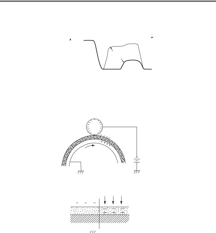
Chapter 2
2.4.1.3 Static Latent Image Formation Block
This block is comprised of two steps and forms static latent images on the photosensitive drum.
When the final step of this block completes, negative charge remains at dark areas on the drum surface where laser beam has not been exposed, and negative charge is eliminated from bright areas on the drum surface with laser beam exposed. The images on the drum with negative charge are called static latent images because human eyes cannot detect them.
|
|
0 |
|
|
|
Time (t) |
|
|
||
|
|
|
|
|
|
|||||
|
|
|
|
|
|
|
|
|
|
|
|
|
|
|
|
|
|
|
|
||
|
|
|
|
|
|
|
|
|||
|
|
|
|
|
|
|
|
|
|
|
Surface |
|
|
|
|
|
|
|
|
||
|
|
Exposed area |
|
|
|
|
||||
|
|
|
|
|
|
|
|
|||
potential |
|
|
Unexposed area |
|
||||||
(V) |
|
|
|
|
|
|
|
|
||
|
|
|
|
|
|
Transfer |
|
|
||
|
|
|
Primary |
Laser |
Primary |
|||||
|
|
|
charging |
beam |
(step 4) |
charging |
||||
|
|
|
(step 1) |
exposure |
|
(step 1) |
||||
|
|
|
|
|
(step 2) |
|
|
|
|
|
|
|
|
|
|
F-2-7 |
|
|
|
|
|
Step 1: Primary charging
For preparation of latent image formation, the surface of photosensitive drum is charged with even negative potential. In this primary charging, the charge is applied from the primary charging roller directly to the photosensitive drum.
DC bias is applied to the primary charging roller to maintain an even potential on the surface of the photosensitive drum.
Primary charging roller
Photosensitive drum
DC bias
F-2-8
Step 2: Laser beam exposure
In this step, static latent images are formed on the photosensitive drum with laser beam.
When laser beams are scanned on the photosensitive drum negatively charged, bright areas lose their charges, eliminating negative potential on the surface of the photosensitive drum; on those portions, static latent images are formed.
Laser beam
|
|
|
|
|
|
|
|
|
|
|
|
|
|
|
|
|
|
|
|
|
|
|
|
|
|
|
|
|
|
|
|
|
|
|
|
|
|
|
|
|
|
Unexposed |
|
|
|
Exposed |
|||||||||
|
|
area |
|
|
|
|
area |
||||||
|
|
|
|
|
|
||||||||
|
|
|
|
|
|
|
|
|
|
|
|
|
F-2-9 |
2-9

Chapter 2
2.4.1.4 Development Block
This block is comprised of one step; it puts toners to the static latent images on the surface of the photosensitive drum and visualizes the images using toner projection development. The toner projection development makes the toner jump on the surface of the photosensitive drum and develops the images.
The toner (developer) used for this equipment is a one-component toner that comprises magnetic body and resin, etc.
Step 3: Development
Toner is affixed to static latent images on the surface of the photosensitive drum.
The toner is charged negatively by friction between the developing cylinder and the surface of the developing blade.
An area on the photosensitive drum exposed with laser beam has higher potential than the developing cylinder; the potential difference between the drum surface and the cylinder enables the toner to jump on the drum surface and makes them visible images.
AC bias superimposed with the development DC negative bias is applied to the developing cylinder.
Blade |
|
|
Developing cylinder |
Exposed area |
AC bias |
Unexposed area |
|
Unexposed area |
Exposed area |
|
|
|
DC bias |
Photosensitive drum
F-2-10
2-10
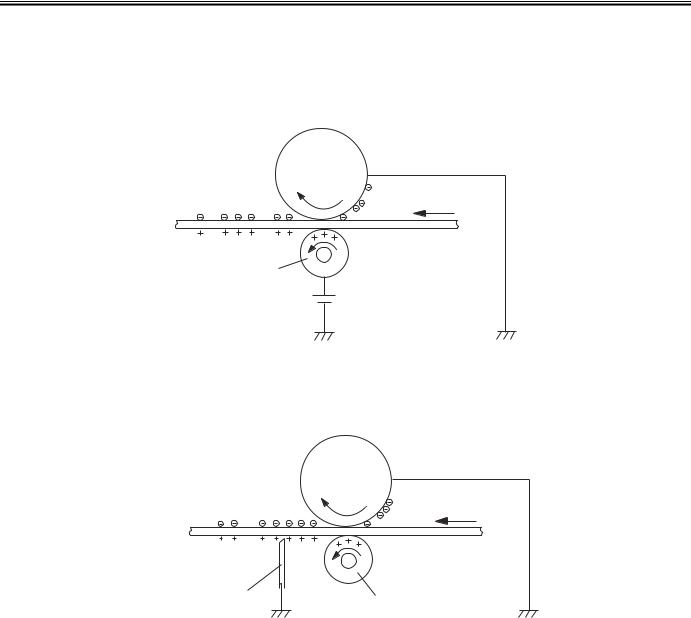
Chapter 2
2.4.1.5 Transfer Block
This block is comprised of two steps; it transfers toner images on the surface of the photosensitive drum to papers.
Step 4: Transfer
In this step, toner images on the photosensitive drum are transferred to papers.
This equipment applies DC positive bias to the transfer roller facing the photosensitive drum and charges papers positively. This enables toner negatively charged on the surface of the photosensitive drum to be transferred to papers.
Photosensitive
drum
Media
Transfer roller
DC bias
F-2-11
Step 5: Separation
In this step, DC negative bias is applied to the static eliminator according to the elasticity of papers to separate the papers from the photosensitive drum. The static eliminator is used to stabilize the paper feed system (prevention of toner stray that appears as polka-dots on print images in a low-temperature, low-humidity environment), and neutralizes the electric charge at the back of papers.
Photosensitive
drum
Media
Static charge eliminator |
Transfer roller |
|
F-2-12
2-11
Loading...