


 Loading...
REVISION 0
FAX-L1000 |
H12-1613 230V EC |
FAX-L1000 |
H12-1614 230V UK |
FAX-L1000 |
H12-1615 230V GER |
FAX-L1000 |
H12-1617 230V FRN |
FAX-L1000 |
H12-1618 230V AUS |
FAX-L1000 |
H12-1619 230V AE |
OPTION MEMORY VII (4MB) |
H11-4721 |
VERIFICATION STAMP UNIT1 |
H12-3162 |
YELLOW INK TO REFILL |
H12-3372 |
FOR VERIFICATION STAMP |
|
PAPER FEED UNIT PF-52 |
R73-5006 |
ENVELOPE FEEDER EF-52 |
R73-5005 |
DUPLEX UNIT DU-52 |
R73-5004 |
FAX-L1000 ISDN KIT |
H11-5553 |
FAX-L1000 Printer Kit |
H11-5513 |
RAM DIMM MODULE |
|
FAX-L1000 PostScript Kit |
H11-5533 |
FAX-L1000 Network |
H11-5543 |
Printer Upgrade kit |
|
FEB. 2000 |
HY8-10AN-000 |
COPYRIGHT © 2000 CANON INC. |
CANON FAX-L1000 FEB. 2000 PRINTED IN JAPAN (IMPRIME AU JAPON) |
Application
This manual has been issued by Canon Inc. for qualified persons to learn technical theory, installation, maintenance, and repair of products. This manual covers all localities where the products are sold. For this reason, there may be information in this manual that does not apply to your locality.
Corrections
This manual may contain technical inaccuracies or typographical errors due to improvements or changes in products. When changes occur in applicable products or in the content of this manual, Canon will release technical information as the need arises. In the event of major changes in the contents of this manual over a long or short period, Canon will issue a new editions of this manual.
The following paragraph does not apply to any countries where such provisions are inconsistent with local
law.
Trademarks
The product names and company names described in this manual are the registered trademarks of the individual companies.
Copyright
This manual is copyrighted with all rights reserved. Under the copyright laws, this manual may not be copied, reproduced or translated into another language, in whole or in part, without the written consent of Canon Inc..
Copyright © 2000 by Canon Inc.
CANON INC.
Office Imaging Products Technical Support Dept. 3
5-1 Hakusan 7-Chome, Toride-city, Ibaraki 302-8501, Japan
DTP System
This manual was produced on an Apple Macintosh® ‚ personal computer, final pages were printed on AGFA SelectSet Avantra 25.
All graphics were produced with Macromedia® FreeHand® 8.0J.
All documents and all page layouts were created with Adobe PageMaker® 6.5J.
I. MEANINGS OF MARKS
The marks used in this manual have the following meanings.
Mark Meaning
Indicates a general caution or warning, or otherwise to communicate the presence of a hazard.
Warns of the possibility of an electric shock.
Informs you of fire-related cautions.
Warns against disassembly of parts.
Informs you that the plug must be removed from the power outlet before starting an operation.
Gives useful information to understand descriptions.
NOTE
Indicates sections to be read to obtain more detailed information.
REFERENCE
I

II. ABOUT THIS MANUAL
This manual consists of the following five chapters, each providing appropriate information needed to service the product.
Chapter 1: Safety and Precautions
Provides cautions and warnings needed when servicing the product while ensuring safety, and explains the protective functions built into the product.
Be sure to go through the descriptions.
Chapter 2: Operating Instructions
Shows how to operate the product correctly, while explaining how to use service data and switches needed for service work.
Chapter 3: Technical Reference
Offers an outline of the product and explains its mechanisms and new features so as to provide a technical understanding of the product.
Chapter 4: Maintenance and Service
Contains information needed to ensure the performance of the product, including adjustments to make during assembly as well as troubleshooting.
Chapter 5: Appendix
Contains information needed for installation, including descriptions related to options.
|
• For more details of user operations and user reports, see the separate volume |
|
of USER’S GUIDE. |
REFERENCE |
• Procedures for assembly/disassembly are not given in this manual. See the |
|
illustrations in the separate volume of PARTS CATALOG.
• Detailed description of each SSSW/parameter is not given in this manual except the new SSSWs/parameters added to this fax.
As necessary, see G3 Facsimile SERVICE DATA HANDBOOK (Rev. 0).
• Detailed description of each error code is not given in this manual except the new error codes added to this fax. As necessary, see G3 Facsimile Error
Code List (Rev. 1) .
II

III. REVISION HISTORY
REVISION |
CONTENT |
|
|
0 |
Original |
|
|
III

IV. TABLE OF CONTENTS
|
|
Chapter 1: Safety and Precautions |
||
Page |
|
|
|
|
1 |
- 1 |
1. DANGER TO PERSONNEL |
||
1 |
- 1 |
1.1 |
Electric Shock |
|
1 |
- 2 |
1.1.1 AC line (AC 230V household current) |
||
1 |
- 2 |
1.1.2 |
Telephone line |
|
1 |
- 2 |
1.1.3 Printer high voltage terminal |
||
1 |
- 3 |
1.2 |
High Temperature Parts |
|
1 |
- 4 |
1.3 |
Fire |
|
1 |
- 6 |
1.4 |
Moving and Rotating Parts |
|
1 |
- 8 |
1.5 |
Laser Beams |
|
1 |
- 10 |
2. DANGER TO EQUIPMENT |
||
1 |
- 10 |
2.1 |
Handling the FAX |
|
1 |
- 12 |
2.2 |
Storage and Handling of FX6 Toner Cartridge |
|
1 |
- 12 |
2.2.1 Before unsealing the box |
||
1 |
- 13 |
2.2.2 |
Storing unsealed parts |
|
1 |
- 13 |
2.2.3 |
Storage environment |
|
1 |
- 13 |
2.2.4 |
Effective life |
|
1 |
- 13 |
2.2.5 |
Handling |
|
1 |
- 15 |
2.3 |
Precautions when Servicing |
|
1 |
- 15 |
2.3.1 Damage due to electrostatic discharge |
||
1 |
- 16 |
2.3.2 |
Lubrication points |
|
1 |
- 16 |
2.3.3 |
Scanner section |
|
1 |
- 17 |
2.3.4 |
Printer section |
|
1 |
- 18 |
2.3.5 |
Paper load section |
|
1 |
- 19 |
2.3.6 |
Control boards |
|
1 |
- 20 |
2.3.7 |
Replacing ROM |
|
1 |
- 21 |
3. PRECAUTIONS FOR DATA PROTECTION |
||
1 |
- 21 |
3.1 |
Battery-backed up Data |
|
1 |
- 22 |
3.2 |
Backed up by Rechargeable Battery |
|
1 |
- 22 |
3.2.1 Data backed up by rechargeable battery |
||
1 |
- 23 |
3.2.2 Reception image data transfer |
||
1 |
- 24 |
3.3 |
Backed up by Lithium Battery |
|
1 |
- 24 |
3.3.1 Data backed up by the lithium battery |
||
1 |
- 26 |
3.3.2 Printing the lithium battery backup data list |
||
1 |
- 28 |
3.4 |
Data clear/initialization using Service Operation |
|
1 |
- 29 |
3.5 |
Master Password |
|
1 |
- 30 |
3.6 |
What to do when a Problem Occurs (All clear) |
|
1 |
- 31 |
4. PROTECTIVE FUNCTIONS |
||
1 |
- 31 |
4.1 |
Reception Image Data Transfer Function |
|
1 |
- 31 |
4.2 |
Data Battery Backup Function |
|
1 |
- 32 |
4.3 |
Built-in Safety Measures |
|
1 |
- 32 |
4.3.1 |
Overcurrent protection |
|
1 |
- 32 |
4.3.2 |
Lightning protection |
|
1 |
- 33 |
4.3.3 |
Power leakage protection |
|
1 |
- 34 |
5. QUALIFICATION REQUIRED FOR INSTALLATION WORK |
||
IV
|
|
Chapter 2: Operating Instructions |
||
2 |
- 1 |
1. NAMES OF PARTS AND THEIR FUNCTIONS |
||
2 |
- 1 |
1.1 |
Main Unit Overview |
|
2 |
- 4 |
1.2 |
Operation Panel |
|
2 |
- 7 |
2. BASIC OPERATION |
||
2 |
- 7 |
2.1 |
Copying |
|
2 |
- 8 |
2.2 |
Telephone (Only possible where a handset or telephone are |
|
|
|
|
connected) |
|
2 |
- 9 |
2.3 |
Transmission |
|
2 |
- 10 |
2.4 |
Reception |
|
2 - 11 |
3. SERVICE OPERATION FUNCTIONS |
|||
2 - 11 |
3.1 |
Report Output Function |
||
2 - 11 |
3.1.1 User report output functions |
|||
2 |
- 13 |
3.1.2 Service report output functions |
||
2 |
- 26 |
3.2 |
User Data Flowchart |
|
2 |
- 39 |
3.3 |
Service Switches |
|
2 |
- 39 |
3.3.1 |
Hardware switches |
|
2 |
- 41 |
3.3.2 |
Service data setting |
|
2 |
- 42 |
3.3.3 Service data registration/setting method |
||
2 |
- 43 |
3.3.4 |
Service data flowchart |
|
2 |
- 49 |
3.3.5 Explanation of SSSW (Service Soft Switch Settings) |
||
2 |
- 50 |
3.3.6 |
New SSSWs/parameters added to this model |
|
2 |
- 66 |
3.4 |
Test Functions |
|
2 |
- 66 |
3.4.1 |
Test mode overview |
|
2 |
- 67 |
3.4.2 |
Test mode flowchart |
|
2 |
- 69 |
3.4.3 |
D-RAM tests |
|
2 |
- 70 |
3.4.4 |
Print test |
|
2 |
- 71 |
3.4.5 Modem and NCU tests |
||
2 |
- 75 |
3.4.6 |
AGING test |
|
2 |
- 76 |
3.4.7 |
Faculty tests |
|
2 |
- 83 |
3.4.8 |
ISDN test |
|
|
|
Chapter 3: Technical Reference |
|
3 |
- 1 |
1. SPECIFICATIONS |
|
3 |
- 1 |
1.1 Overview |
|
3 |
- 1 |
1.1.1 |
Facsimile overview |
3 |
- 2 |
1.1.2 |
Option overview |
3 |
- 3 |
1.2 Configuration and Structure |
|
3 |
- 3 |
1.2.1 |
Product names |
3 |
- 3 |
1.2.2 |
External view |
3 |
- 4 |
1.2.3 |
Configuration |
3 |
- 5 |
1.3 Specifications and Functions |
|
3 |
- 5 |
1.3.1 |
Basic specifications |
3 |
- 6 |
1.3.2 |
Communications specifications |
3 |
- 8 |
1.3.3 |
Scanner section specifications |
3 - 11 |
1.3.4 |
Printer section specifications |
|
3 |
- 14 |
1.3.5 |
Functions |
3 |
- 18 |
2. THEORY OF OPERATIONS |
|
3 |
- 18 |
2.1 Product Overview |
|
3 |
- 18 |
2.1.1 |
Fax main unit |
V
3 |
- 18 |
2.1.2 |
Option overview |
|
3 |
- 19 |
2.1.3 |
Consumables |
|
3 |
- 21 |
2.2 |
Mechanical Overview |
|
3 |
- 21 |
2.2.1 |
Unit layout diagrams |
|
3 |
- 21 |
2.2.2 |
Document and recording paper flow |
|
3 |
- 23 |
2.2.3 |
Drive system layout |
|
3 |
- 25 |
2.2.4 |
Electrical system layout |
|
3 |
- 30 |
2.3 |
Scanner Section |
|
3 |
- 30 |
2.3.1 |
Document feed section |
|
3 |
- 35 |
2.3.2 |
Optical section |
|
3 |
- 38 |
2.4 |
Paper Load Section |
|
3 |
- 44 |
2.5 |
Printer Section |
|
3 |
- 45 |
2.5.1 |
Paper feed/eject section |
|
3 |
- 48 |
2.5.2 |
LASER/Scanner section |
|
3 |
- 50 |
2.5.3 |
Toner cartridge |
|
3 |
- 56 |
2.5.4 |
Transfer/Separation section |
|
3 |
- 57 |
2.5.5 |
Fixing section |
|
3 |
- 60 |
2.6 |
Circuit Overview |
|
3 |
- 60 |
2.6.1 |
SCNT board function block diagram |
|
3 |
- 61 |
2.6.2 |
Functions |
|
3 |
- 64 |
2.6.3 |
ECNT board function block diagra |
|
3 |
- 65 |
2.6.4 |
Functions |
|
3 |
- 67 |
2.6.5 SCNT board component block diagram |
||
3 |
- 71 |
2.6.6 ECNT board component block diagram |
||
3 |
- 73 |
2.6.7 |
Flow of image signals |
|
3 |
- 77 |
3. NEW FUNCTION |
||
3 |
- 77 |
3.1 |
High-speed Transmission |
|
3 |
- 77 |
3.1.1 |
V.8/V.34 protocol |
|
3 |
- 91 |
3.2 |
JBIG Image Compression Encoding Method |
|
3 |
- 91 |
3.2.1 |
Outline of the JBIG Image Compression Encoding Method |
|
3 |
- 92 |
3.2.2 |
Single Progression Sequential Bi-level Image Compression Method |
|
3 |
- 93 |
3.2.3 |
Encoding Method |
|
3 |
- 100 |
3.2.4 |
Construction of image data with JBIG Image Compression |
|
|
|
|
|
Encoding |
3 |
- 101 |
3.2.5 |
Explanation of Bi-level Image Header section (BIH) |
|
3 |
- 102 |
3.2.6 |
Explanation and parameters for each symbol used in BIH |
|
3 |
- 103 |
3.2.7 |
Explanation of Bi-level Image Data (BID) section |
|
3 |
- 103 |
3.2.8 |
Explanation and parameters for each symbol used in BID |
|
3 |
- 105 |
3.3 |
Energy Save Standby (ESS) |
|
|
|
Chapter 4: Maintenance and Service |
||
4 |
- 1 |
1. MAINTENANCE |
||
4 |
- 1 |
1.1 |
Maintenance Items |
|
4 |
- 1 |
1.1.1 |
Consumables |
|
4 |
- 3 |
1.1.2 |
Cleaning |
|
4 |
- 5 |
1.1.3 |
Periodic inspections |
|
4 |
- 5 |
1.1.4 |
Periodic replacement parts |
|
4 |
- 6 |
1.2 |
Tools |
|
4 |
- 6 |
1.2.1 |
General tools |
|
4 |
- 6 |
1.2.2 |
Special tools |
|
VI
4 - 7 2. CONSUMABLES REPLACEMENT
4 - 7 2.1 Toner Cartridge
4 - 7 2.2 Recording Paper
4 - 8 2.3 Stamp Ink
4 - 11 3. CLEANING
4 - 11 3.1 Main Unit
4 - 11 3.2 Document Pick-up Roller
4 - 11 3.3 Separation Roller (Upper)
4 - 11 3.4 Separation Roller (Lower)
4 - 11 3.5 Scanning Glass (Contact Sensor)
4 - 11 3.6 White Sheet
4 - 11 3.7 Document Feed Roller 1
4 - 11 3.8 Document Feed Roller 2
4 - 11 3.9 Document Eject Roller
4 - 13 3.10 Transfer Guide
4 - 16 3.11 Transfer Charging Roller
4 - 18 3.12 Cassette Pick-Up Roller/Feed Roller/Separation Roller 4 - 20 3.13 Multi-Purpose Tray Pick-Up Roller/Separation Pad
4 - 22 3.14 Feed Roller
4 - 27 3.15 Pre-Transfer Roller and Registration Arm
4 - 29 3.16 Paper Feed Belt and Paper Feed Guide 4 - 31 3.17 Fixing Unit Entrance Guide
4 - 32 3.18 Fixing Film
4 - 35 3.19 Face-Up Deflector, Fixing Delivery Roller and Lower Paper
Delivery Guide
4 - 35 4. ADJUSTMENT
4 - 35 4.1 Parts Replacement
4 - 35 4.2 Points to Grease
4 - 35 4.3 Adjustment items
4 - 36 4.4 Leading Edge Margin Adjustment
4 - 38 5. TROUBLESHOOTING
4 - 38 5.1 Troubleshooting
4 - 38 5.1.1 Repairs
4 - 38 5.1.2 Precautions for troubleshooting
4 - 39 5.2 Error Shown on the Display
4 - 39 5.2.1 User error message
4 - 45 5.2.2 Error codes
4 - 64 5.3 Errors not Shown on the Display 4 - 80 6. WIRING DIAGRAM
4 - 80 6.1 Wiring Diagram
4 - 83 6.2 Signal Description
Chapter 5: Appendix
5 - 1 1. INSTALLATION
5 - 2 1.1 Setting up the Fax
5 - 6 1.2 Unpacking
5 - 10 1.3 Removing the Shipping Material
5 - 14 1.4 Assembling the Fax
5 - 41 1.5 Checking Operations
5 - 42 1.6 Moving the Fax Unit
VII
5 |
- 43 |
2. SERVICE TOOLS |
|
5 |
- 43 |
2.1 Printer Driver Tester |
|
5 |
- 43 |
2.1.1 |
Outline |
5 |
- 44 |
2.1.2 |
Explanation of LEDs and Switches |
5 |
- 45 |
2.1.3. Operation |
|
5 |
- 51 |
3. OPTION |
|
5 |
- 51 |
3.1 Option Memory VII (4M-BYTE) |
|
5 |
- 51 |
3.1.1 |
Safety and precautions |
5 |
- 51 |
3.1.2 |
Service operations |
5 |
- 57 |
3.1.3 |
Technical information |
5 |
- 58 |
3.1.4 |
Maintenance and service |
5 |
- 61 |
3.2 Verification Stamp Unit |
|
5 |
- 61 |
3.2.1 |
Service operations |
5 |
- 65 |
3.2.2 |
Maintenance and service |
5 |
- 66 |
3.3 Paper Feed Unit PF-52 |
|
5 |
- 66 |
3.3.1 |
Safety and precautions |
5 |
- 67 |
3.3.2 |
Service operations |
5 |
- 70 |
3.3.3 |
Technical information |
5 |
- 72 |
3.3.4 |
Operations |
5 |
- 75 |
3.3.5 |
Maintenance and service |
5 |
- 77 |
3.3.6 |
Recording Paper Size Priority |
5 |
- 81 |
3.4 Envelope Feeder EF-52 |
|
5 |
- 81 |
3.4.1 |
Service operations |
5 |
- 82 |
3.4.2 |
Technical information |
5 |
- 83 |
3.4.3 |
Operation |
5 |
- 85 |
3.4.4 |
Maintenance and service |
5 |
- 88 |
3.4.5 |
Installation Position Adjustment of Separation Guide of Envelope |
|
|
|
Feeder (adjustment of gap between separation guide and lower |
|
|
|
separation roller) |
5 |
- 89 |
3.4.6 |
Installation Position Adjustment of Envelope Multiple Feed Sensor |
5 |
- 91 |
3.5 Duplex Unit DU-52 |
|
5 |
- 91 |
3.5.1 |
Service operations |
5 |
- 92 |
3.5.2 |
Technical information |
5 |
- 93 |
3.5.3 |
Operation |
5 |
- 98 |
3.5.4 |
Maintenance and service |
5 |
- 103 |
3.6 FAX-L1000 ISDN Kit |
|
5 |
- 103 |
3.6.1 |
Safety and precautions |
5 |
- 103 |
3.6.2 |
Service operations |
5 - 112 |
3.6.3 |
Technical information |
|
5 |
- 157 |
3.6.4 G4 board components |
|
5 |
- 159 |
3.6.5 |
Flow of Image Signals |
5 |
- 163 |
3.6.6 |
ISDN Protocol Messages |
5 |
- 171 |
3.6.7 |
Maintenance and service |
5 |
- 202 |
3.7 FAX-L1000 Network Printer Upgrade kit |
|
5 |
- 202 |
3.7.1 |
Safety and precautions |
5 |
- 202 |
3.7.2 |
Service operations |
5 |
- 203 |
3.7.3 |
Technical information |
5 |
- 205 |
3.7.4 |
Maintenance and Service |
5 |
- 209 |
3.8 FAX-L1000 PostScript kit |
|
5 |
- 209 |
3.8.1 |
Safety and precautions |
VIII
5 - 209 |
3.8.2 |
Service operations |
5 - 214 |
3.8.3 |
Technical Information |
5 - 214 |
3.8.4 |
Maintenance and service |
5 - 215 |
3.9 RAM DIMM Module |
|
5 - 215 |
3.9.1 |
Safety and precautions |
5 - 215 |
3.9.2 |
Service operations |
5 - 217 |
3.9.3 |
Technical informations |
5 - 218 |
3.9.4 |
Maintenance and service |
5 - 219 |
3.10 FAX-L1000 Printer kit |
|
5 - 219 |
3.10.1 |
Safety and precautions |
5 - 219 |
3.10.2 |
Service operations |
5 - 223 |
3.10.3 |
Technical informations |
5 - 235 |
3.10.4 |
Maintenance and service |
IX

V. ILLUSTRATION INDEX
|
|
Chapter 1: Safety and Precautions |
|||
Page |
|
|
|
|
|
1 |
- 2 |
Figure |
1 - 1 |
Printer High Voltage Terminal |
|
1 |
- 3 |
Figure |
1 - 2 |
High Temperature Parts |
|
1 |
- 7 |
Figure |
1 |
- 3 |
Moving and Rotating Parts |
1 |
- 8 |
Figure |
1 |
- 4 LASER beam warning label |
|
1 |
- 9 |
Figure |
1 |
- 5 |
Laser Shutter |
1 |
- 10 |
Figure |
1 |
- 6 |
Precautions 1 |
1 - 11 |
Figure |
1 |
- 7 |
Precautions 2 |
|
1 |
- 13 |
Figure |
1 |
- 8 |
Proper Way to Shake Cartridge |
1 |
- 14 |
Figure |
1 |
- 9 |
Cautions for Handling |
1 |
- 17 |
Figure |
1 |
- 10 |
Printer Section |
1 |
- 18 |
Figure |
1 |
- 11 |
Pickup Roller Initial Position |
1 |
- 21 |
Figure |
1 |
- 12 |
Lithium / Rechargeable Battery and Jumper Plugs |
1 |
- 23 |
Figure |
1 - 13 Reception Image Data Transfer Method |
||
1 |
- 30 |
Figure |
1 |
- 14 |
All Clear |
1 |
- 12 |
Table |
1 - 1 |
Environmental conditions |
|
|
|
Chapter 2: Operating Instructions |
|||
2 |
- 1 |
Figure |
2 - 1 |
Front View |
|
2 |
- 2 |
Figure |
2 |
- 2 |
Rear View |
2 |
- 4 |
Figure |
2 |
- 3 |
Operation Panel 1 |
2 |
- 5 |
Figure |
2 |
- 4 |
Operation Panel 2 |
2 |
- 6 |
Figure |
2 |
- 5 |
Operation Panel 3 |
2 |
- 7 |
Figure |
2 |
- 6 |
Display for document set |
2 |
- 8 |
Figure |
2 |
- 7 Document Guides Adjustment |
|
2 |
- 8 |
Figure |
2 |
- 8 |
Document Load Limit |
2 |
- 12 |
Figure |
2 |
- 9 |
Memory Clear List |
2 |
- 14 |
Figure |
2 |
- 10 |
System Data List (1/7) |
2 |
- 15 |
Figure |
2 |
- 11 |
System Data List (2/7) |
2 |
- 16 |
Figure |
2 |
- 12 |
System Data List (3/7) |
2 |
- 17 |
Figure |
2 |
- 13 |
System Data List (4/7) |
2 |
- 18 |
Figure |
2 |
- 14 |
System Data List (5/7) |
2 |
- 19 |
Figure |
2 |
- 15 |
System Data List (6/7) |
2 |
- 20 |
Figure |
2 |
- 16 |
System Data List (7/7) |
2 |
- 21 |
Figure |
2 |
- 17 |
System Dump List (1/2) |
2 |
- 23 |
Figure |
2 |
- 18 |
System Dump List (2/2) |
2 |
- 24 |
Figure |
2 |
- 19 |
Service Error Activity Report |
2 |
- 26 |
Figure |
2 |
- 20 |
User Menu Settings (1/13) |
2 |
- 27 |
Figure |
2 |
- 21 |
User Menu Settings (2/13) |
2 |
- 28 |
Figure |
2 |
- 22 |
User Menu Settings (3/13) |
2 |
- 29 |
Figure |
2 |
- 23 |
User Menu Settings (4/13) |
2 |
- 30 |
Figure |
2 |
- 24 |
User Menu Settings (5/13) |
2 |
- 31 |
Figure |
2 |
- 25 |
User Menu Settings (6/13) |
2 |
- 32 |
Figure |
2 |
- 26 |
User Menu Settings (7/13) |
2 |
- 33 |
Figure |
2 |
- 27 |
User Menu Settings (8/13) |
2 |
- 34 |
Figure |
2 |
- 28 |
User Menu Settings (9/13) |
X
2 |
- 35 |
Figure |
2 |
- 29 |
User Menu Settings (10/13) |
2 |
- 36 |
Figure |
2 |
- 30 |
User Menu Settings (11/13) |
2 |
- 37 |
Figure |
2 |
- 31 |
User Menu Settings (12/13) |
2 |
- 38 |
Figure |
2 |
- 32 |
User Menu Settings (13/13) |
2 |
- 40 |
Figure |
2 |
- 33 |
Slide Switch Location on NCU Board |
2 |
- 40 |
Figure |
2 |
- 34 |
Slide Switch Setting |
2 |
- 42 |
Figure |
2 |
- 35 |
Service Data Setting Method |
2 |
- 43 |
Figure |
2 |
- 36 |
Service Data (1/6) |
2 |
- 44 |
Figure |
2 |
- 37 |
Service Data (2/6) |
2 |
- 45 |
Figure |
2 |
- 38 |
Service Data (3/6) |
2 |
- 46 |
Figure |
2 |
- 39 |
Service Data (4/6) |
2 |
- 47 |
Figure |
2 |
- 40 |
Service Data (5/6) |
2 |
- 48 |
Figure |
2 |
- 41 |
Service Data (6/6) |
2 |
- 49 |
Figure |
2 |
- 42 |
Bit Switch Display |
2 |
- 49 |
Figure |
2 |
- 43 |
How to Read Bit Switch Tables |
2 |
- 67 |
Figure |
2 |
- 44 Test Mode (1/2) |
|
2 |
- 68 |
Figure |
2 |
- 45 Test Mode (2/2) |
|
2 |
- 69 |
Figure |
2 |
- 46 |
D-RAM Test |
2 |
- 70 |
Figure |
2 |
- 47 |
Print Pattern Check |
2 |
- 73 |
Figure |
2 |
- 48 Tonal and DTMF Signal Reception Tests |
|
2 |
- 77 |
Figure |
2 |
- 49 |
Sensor Tests |
2 |
- 78 |
Figure |
2 |
- 50 Toner Sensor |
|
2 |
- 79 |
Figure |
2 |
- 51 |
Stamp Test |
2 |
- 82 |
Figure |
2 |
- 52 |
Operation Panel |
|
|
Chapter 3: Technical Reference |
|||
3 |
- 3 |
Figure |
3 |
- 1 |
External View |
3 |
- 10 |
Figure |
3 |
- 2 Scanning Range |
|
3 |
- 13 |
Figure |
3 |
- 3 |
Printing Range |
3 |
- 20 |
Figure |
3 |
- 4 |
Product Overview |
3 |
- 22 |
Figure |
3 |
- 5 |
Paper Path |
3 |
- 24 |
Figure |
3 |
- 6 |
Drive System Layout |
3 |
- 26 |
Figure |
3 |
- 7 |
Electrical System Layout |
3 |
- 29 |
Figure |
3 |
- 8 Arrangement of Sensors |
|
3 |
- 31 |
Figure |
3 |
- 9 Document Feed Section |
|
3 |
- 33 |
Figure |
3 |
- 10 |
Stopper Movement |
3 |
- 37 |
Figure |
3 |
- 11 |
Contact Sensor |
3 |
- 40 |
Figure |
3 |
- 12 |
Cassette Paper Loading |
3 |
- 43 |
Figure |
3 |
- 13 |
Paper Size Detection Configuration (Paper feeder) |
3 |
- 43 |
Figure |
3 |
- 14 |
Paper Size Detection Configuration (Option paper feed |
|
|
|
|
|
unit PF-52) |
3 |
- 44 |
Figure |
3 |
- 15 |
Printer Section |
3 |
- 46 |
Figure |
3 |
- 16 |
Paper Feed/Eject Section |
3 |
- 48 |
Figure |
3 |
- 17 |
LASER/Scanner Section |
3 |
- 50 |
Figure |
3 |
- 18 Toner Cartridge |
|
3 |
- 51 |
Figure |
3 |
- 19 |
Surface Potential |
3 |
- 51 |
Figure |
3 |
- 20 |
Primary Charging |
3 |
- 52 |
Figure |
3 |
- 21 Laser Beam Exposure |
|
3 |
- 52 |
Figure |
3 |
- 22 |
Developing |
3 |
- 53 |
Figure |
3 |
- 23 |
Developing Cylinder/Drum Surface Potential |
XI
3 |
- 54 |
Figure |
3 |
- 24 |
Drum Cleaning |
3 |
- 55 |
Figure |
3 |
- 25 |
High Voltage Terminals |
3 |
- 56 |
Figure |
3 - 26 |
Transfer |
|
3 |
- 56 |
Figure |
3 |
- 27 |
Separation |
3 |
- 57 |
Figure |
3 |
- 28 |
Fixing section |
3 |
- 60 |
Figure |
3 |
- 29 |
Function Block Diagram (1) |
3 |
- 64 |
Figure |
3 |
- 30 |
Function Block Diagram (2) |
3 |
- 67 |
Figure |
3 |
- 31 |
Component Block Diagram (1) |
3 |
- 71 |
Figure |
3 |
- 32 |
Component Block Diagram (2) |
3 |
- 74 |
Figure |
3 - 33 |
Transmission |
|
3 |
- 76 |
Figure |
3 |
- 34 |
Reception |
3 |
- 79 |
Figure |
3 |
- 35 |
Typical Protocol |
3 |
- 86 |
Figure |
3 |
- 36 |
Late Start |
3 |
- 87 |
Figure |
3 |
- 37 |
Between-page Sequence |
3 |
- 88 |
Figure |
3 |
- 38 |
Mode Change |
3 |
- 89 |
Figure |
3 |
- 39 |
Image Transmission Speed Change from the Receiver |
3 |
- 90 |
Figure |
3 |
- 40 |
Image Transmission Speed Change from the |
|
|
|
|
|
Transmitter |
3 |
- 91 |
Figure |
3 |
- 41 |
Images |
3 |
- 93 |
Figure |
3 |
- 42 |
Encoder and Flow of JBIG Encoding |
3 |
- 94 |
Figure |
3 |
- 43 |
Model Templates |
3 |
- 95 |
Figure |
3 - 44 |
Positions of Pixels in Model Template |
|
3 |
- 96 |
Figure |
3 |
- 45 |
Study Table Study Example 1 |
3 |
- 96 |
Figure |
3 |
- 46 |
Study Table Study Example 2 |
3 |
- 98 |
Figure |
3 - 47 |
Arithmetic Encoding Conceptual Diagram |
|
3 |
- 99 |
Figure |
3 |
- 48 When Predictions are Continually Accurate |
|
3 |
- 100 |
Figure |
3 |
- 49 |
Construction of JBIG Image Data |
3 |
- 100 |
Figure |
3 |
- 50 |
BIE Construction Diagram |
3 |
- 101 |
Figure |
3 |
- 51 |
BIH Construction Diagram |
3 |
- 103 |
Figure |
3 |
- 52 |
BID Construction Diagram |
3 |
- 105 |
Figure |
3 |
- 53 |
System Block Diagram |
3 |
- 95 |
Table |
3 |
- 1 |
Study Table (Initial values) |
3 |
- 95 |
Table |
3 |
- 2 |
Probability Estimation Table |
|
|
Chapter 4: Maintenance and Service |
|||
4 |
- 8 |
Figure |
4 |
- 1 |
Refilling the Stamp Ink 1 |
4 |
- 9 |
Figure |
4 |
- 2 |
Refilling the Stamp Ink 2 |
4 |
- 9 |
Figure |
4 |
- 3 |
Refilling the Stamp Ink 3 |
4 |
- 12 |
Figure |
4 |
- 4 |
Cleaning Location 1 |
4 |
- 12 |
Figure |
4 |
- 5 |
Cleaning Location 2 |
4 |
- 13 |
Figure |
4 |
- 6 |
Preparation for Cleaning 1 |
4 |
- 13 |
Figure |
4 |
- 7 |
Preparation for Cleaning 2 |
4 |
- 14 |
Figure |
4 |
- 8 |
Cleaning Location 1 |
4 |
- 14 |
Figure |
4 |
- 9 |
Cleaning Location 2 |
4 |
- 15 |
Figure |
4 |
- 10 |
Cleaning Location 3 |
4 |
- 16 |
Figure |
4 - 11 |
Preparation for Cleaning |
|
4 |
- 17 |
Figure |
4 |
- 12 |
Cleaning Location |
4 |
- 18 |
Figure |
4 |
- 13 |
Preparation for Cleaning 1 |
4 |
- 18 |
Figure |
4 |
- 14 |
Preparation for Cleaning 2 |
4 |
- 19 |
Figure |
4 |
- 15 |
Cleaning Location 1 |
XII
4 - 19 |
Figure |
4 |
- 16 |
Cleaning Location 2 |
4 - 20 |
Figure |
4 |
- 17 |
Preparation for Cleaning 1 |
4 - 20 |
Figure |
4 |
- 18 |
Preparation for Cleaning 2 |
4 - 21 |
Figure |
4 |
- 19 |
Cleaning Location 1 |
4 - 21 |
Figure |
4 |
- 20 |
Cleaning Location 2 |
4 - 22 |
Figure |
4 |
- 21 |
Preparation for Cleaning 1 |
4 - 22 |
Figure |
4 |
- 22 |
Preparation for Cleaning 2 |
4 - 23 |
Figure |
4 |
- 23 |
Preparation for Cleaning 3 |
4 - 23 |
Figure |
4 |
- 24 |
Preparation for Cleaning 4 |
4 - 24 |
Figure |
4 |
- 25 |
Preparation for Cleaning 5 |
4 - 24 |
Figure |
4 |
- 26 |
Preparation for Cleaning 6 |
4 - 25 |
Figure |
4 |
- 27 |
Preparation for Cleaning 7 |
4 - 25 |
Figure |
4 |
- 28 |
Preparation for Cleaning 8 |
4 - 26 |
Figure |
4 |
- 29 |
Cleaning Location |
4 - 27 |
Figure |
4 |
- 30 |
Preparation for Cleaning 1 |
4 - 27 |
Figure |
4 |
- 31 |
Preparation for Cleaning 2 |
4 - 28 |
Figure |
4 |
- 32 |
Cleaning Location |
4 - 29 |
Figure |
4 |
- 33 |
Preparation for Cleaning |
4 - 29 |
Figure |
4 |
- 34 |
Cleaning Location 1 |
4 - 30 |
Figure |
4 |
- 35 |
Cleaning Location 2 |
4 - 31 |
Figure |
4 |
- 36 |
Preparation for Cleaning |
4 - 31 |
Figure |
4 |
- 37 |
Cleaning Location |
4 - 32 |
Figure |
4 |
- 38 |
Preparation for Cleaning 1 |
4 - 32 |
Figure |
4 |
- 39 |
Preparation for Cleaning 2 |
4 - 33 |
Figure |
4 |
- 40 |
Preparation for Cleaning 3 |
4 - 33 |
Figure |
4 |
- 41 |
Cleaning Location |
4 - 34 |
Figure |
4 |
- 42 |
Preparation for Cleaning |
4 - 34 |
Figure |
4 |
- 43 |
Cleaning Location |
4 - 37 |
Figure |
4 |
- 44 |
Leading Edge Margin Adjustment |
4 - 45 |
Figure |
4 |
- 45 |
Service Error Code Display |
4 - 67 |
Figure |
4 |
- 46 |
Faulty Print Samples |
4 - 73 |
Figure |
4 |
- 47 |
Fixing Nip Width |
4 - 80 |
Figure |
4 |
- 48 |
Wiring Diagram (1) |
4 - 81 |
Figure |
4 |
- 49 |
Wiring Diagram (2) |
4 - 82 |
Figure |
4 |
- 50 |
Wiring Diagram (3) |
|
Chapter 5: Appendix |
|||
5 - 40 |
Figure |
5 |
- 1 All Clear |
|
5 - 41 |
Figure |
5 |
- 2 |
Copy Operation |
5 - 43 |
Figure |
5 |
- 3 |
Printer Driver Tester |
5 - 44 |
Figure |
5 |
- 4 LEDs and Switches |
|
5 - 45 |
Figure |
5 |
- 5 |
Connect Printer Driver Tester |
5 - 51 |
Figure |
5 |
- 6 |
External View |
5 - 52 |
Figure |
5 |
- 7 |
Preparations for Installation 1 |
5 - 52 |
Figure |
5 |
- 8 |
Preparations for Installation 2 |
5 - 53 |
Figure |
5 |
- 9 |
DRAM Boards Installation (1) |
5 - 54 |
Figure |
5 |
- 10 |
DRAM Boards Installation (2) |
5 - 55 |
Figure |
5 |
- 11 |
Flowchart of D-RAM test 1 |
5 - 55 |
Figure |
5 |
- 12 |
D-RAM Board Installation Check |
5 - 57 |
Figure |
5 |
- 13 DRAM Board (4MB) |
|
XIII
5 |
- 61 |
Figure |
5 - 14 |
External View |
||
5 |
- 61 |
Figure |
5 - 15 |
Attachment to the Main Unit 1 |
||
5 |
- 62 |
Figure |
5 - 16 |
Attachment to the Main Unit 2 |
||
5 |
- 62 |
Figure |
5 - 17 |
Attachment to the Main Unit 3 |
||
5 |
- 63 |
Figure |
5 - 18 |
Attachment to the Main Unit 4 |
||
5 |
- 63 |
Figure |
5 - 19 |
Attachment to the Main Unit 5 |
||
5 |
- 64 |
Figure |
5 - 20 Flowchart of Changing SSSW |
|||
5 |
- 66 |
Figure |
5 - 21 |
Moving and Rotating Parts |
||
5 |
- 67 |
Figure |
5 - 22 |
External View |
||
5 |
- 69 |
Figure |
5 - 23 |
Pickup Roller Initial Position |
||
5 |
- 70 |
Figure |
5 - 24 |
External View |
||
5 |
- 72 |
Figure |
5 - 25 |
Cross-Sectional Diagram |
||
5 |
- 73 |
Figure |
5 - 26 |
Arrangement of Switches |
||
5 |
- 74 |
Figure |
5 - 27 |
Electrical Circuit Section |
||
5 |
- 78 |
Figure |
5 - 28 |
Reading the Recording Paper Size Table |
||
5 |
- 81 |
Figure |
5 - 29 |
External View |
||
5 |
- 82 |
Figure |
5 - 30 |
External View |
||
5 |
- 83 |
Figure |
5 - 31 |
Envelope Feeder |
||
5 |
- 83 |
Figure |
5 - 32 |
Cross-Sectional Diagram |
||
5 |
- 84 |
Figure |
5 - 33 |
Arrangement of Sensors |
||
5 |
- 84 |
Figure |
5 - 34 |
Electrical Circuit Section |
||
5 |
- 88 |
Figure |
5 - 35 |
Adjustment of Separation Guide |
||
5 |
- 90 |
Figure |
5 - 36 |
Adjustment of Envelope Multiple Feed Sensor |
||
5 |
- 91 |
Figure |
5 - 37 |
External View |
||
5 |
- 92 |
Figure |
5 - 38 |
External View |
||
5 |
- 95 |
Figure |
5 - 39 |
Duplexing Unit |
||
5 |
- 95 |
Figure |
5 - 40 |
Cross-Sectional Diagram |
||
5 |
- 96 |
Figure |
5 - 41 |
Arrangement of Sensors |
||
5 |
- 97 |
Figure |
5 - 42 |
Electrical Circuit Section |
||
5 |
- 103 |
Figure |
5 - 43 |
External View |
||
5 |
- 104 |
Figure |
5 - 44 |
Preparations for Installation 1 |
||
5 |
- 105 |
Figure |
5 - 45 |
Preparation for Installation 2 |
||
5 |
- 105 |
Figure |
5 - 46 |
Preparation for Installation 3A |
||
5 |
- 106 |
Figure |
5 - 47 |
Preparation for Installation 3B |
||
5 |
- 106 |
Figure |
5 - 48 |
Preparation for Installation 4 |
||
5 |
- 107 |
Figure |
5 - 49 |
FAX-L1000 ISDN Kit Installation |
||
5 |
- 108 |
Figure |
5 - 50 |
FAX-L1000 Printer Kit (Option) Installation |
||
5 |
- 109 |
Figure |
5 - 51 ROM Replacement 1 |
|||
5 |
- 109 |
Figure |
5 - 52 ROM Replacement 2 |
|||
5 - 110 |
Figure |
5 - 53 |
All Clear Operation |
|||
5 - 111 |
Figure |
5 - 54 |
ROM Version Check |
|||
5 - 112 |
Figure |
5 - 55 |
External View |
|||
5 |
- 124 |
Figure |
5 - 56 |
G4 |
/ G3 |
Fallback Procedure (1) |
5 |
- 125 |
Figure |
5 - 57 |
G4 |
/ G3 |
Fallback Procedure (2) |
5 |
- 138 |
Figure |
5 - 58 |
System Data List (1/10) |
||
5 |
- 139 |
Figure |
5 - 59 |
System Data List (2/10) |
||
5 |
- 140 |
Figure |
5 - 60 |
System Data List (3/10) |
||
5 |
- 141 |
Figure |
5 - 61 |
System Data List (4/10) |
||
5 |
- 142 |
Figure |
5 - 62 |
System Data List (5/10) |
||
5 |
- 143 |
Figure |
5 - 63 |
System Data List (6/10) |
||
XIV
5 |
- 144 |
Figure |
5 |
- 64 |
System Data List (7/10) |
5 |
- 145 |
Figure |
5 |
- 65 |
System Data List (8/10) |
5 |
- 146 |
Figure |
5 |
- 66 |
System Data List (9/10) |
5 |
- 147 |
Figure |
5 |
- 67 |
System Data List (10/10) |
5 |
- 148 |
Figure |
5 |
- 68 |
System Dump List (1/3) |
5 |
- 149 |
Figure |
5 |
- 69 |
System Dump List (2/3) |
5 |
- 150 |
Figure |
5 |
- 70 |
System Dump List (3/3) |
5 |
- 151 |
Figure |
5 |
- 71 |
Dch Log Report |
5 |
- 155 |
Figure |
5 - 72 Bch Log Report |
||
5 |
- 157 |
Figure |
5 |
- 73 |
Component block diagram |
5 |
- 159 |
Figure |
5 - 74 Transmission Image Signal Flow |
||
5 |
- 161 |
Figure |
5 |
- 75 |
Reception Image Signal Flow |
5 |
- 167 |
Figure |
5 |
- 76 |
D-Channel Protocol Flow |
5 |
- 169 |
Figure |
5 |
- 77 |
B-Channel Protocol Flow (G4) |
5 |
- 170 |
Figure |
5 |
- 78 |
B-Channel Protocol Flow (G3) |
5 |
- 202 |
Figure |
5 |
- 79 |
External View |
5 |
- 204 |
Figure |
5 |
- 80 |
Status LEDs |
5 |
- 206 |
Figure |
5 |
- 81 |
Connector Locations |
5 |
- 209 |
Figure |
5 |
- 82 |
External View |
5 |
- 215 |
Figure |
5 |
- 83 |
External View |
5 |
- 219 |
Figure |
5 |
- 84 |
External View |
5 |
- 220 |
Figure |
5 |
- 85 |
Preparations for Installation 1 |
5 |
- 220 |
Figure |
5 |
- 86 |
Preparations for Installation 2 |
5 |
- 221 |
Figure |
5 |
- 87 |
FAX-L1000 Printer Kit Installation |
5 |
- 223 |
Figure |
5 |
- 88 |
External View |
5 |
- 228 |
Figure |
5 - 89 |
Options |
|
5 |
- 229 |
Figure |
5 - 90 |
Flow of Print Data 1 |
|
5 |
- 230 |
Figure |
5 - 91 |
Flow of Print Data 2 |
|
5 |
- 231 |
Figure |
5 - 92 PDL Menu Flow |
||
5 |
- 233 |
Figure |
5 |
- 93 |
Components |
5 |
- 234 |
Figure |
5 |
- 94 |
Block Diagram |
5 |
- 236 |
Figure |
5 |
- 95 Test Print |
|
5 |
- 237 |
Figure |
5 |
- 96 |
Cleaning Page |
5 |
- 47 |
Table |
5 |
- 1 |
Printer Operation Setting |
5 |
- 48 |
Table |
5 |
- 2 |
Printer Condition (1) |
5 |
- 49 |
Table |
5 |
- 3 |
Printer Condition (2) |
XV
This page intentionally left blank

Chapter 1
Safety and
Precautions
FAX-L1000 Chapter 1: Safety and Precautions
1.DANGER TO PERSONNEL
1.1Electric Shock
Precautions
Before disassembling the fax, carry out the following to prevent electric shock:
(1)Disconnect the power cord from the outlet.
(2)Disconnect the modular jack cord (telephone line) from the fax.
Precautions when servicing the fax with the power on
When you must service the fax with the power cord plugged in, you must not ground your body with grounding wrist straps.
This is to prevent electricity passing to your body.
1-1

FAX-L1000 Chapter 1: Safety and Precautions
1.1.1 AC line (AC 230V household current)
Power supply unit (primary side)
The AC 230V is supplied to the primary side of the power supply unit when the power cord is plugged in.
1.1.2 Telephone line
NCU board (primary side)
When connected to the telephone line, a line voltage of approx. DC 48V is supplied to the fax from the telephone line.
And when the ringing signal is received, approx. AC 90Vrms is supplied.
1.1.3 Printer high voltage terminal
When the printer cover sensor is pressed with the printer cover closed, voltage of approx. AC 1600V p-p maximum is supplied to the printer high voltage terminal. When you press the printer cover sensor, be careful not to touch the high voltage terminal.
High voltage terminal
Printer cover
Printer cover sensor
Figure 1-1 Printer High Voltage Terminal
1-2
FAX-L1000 Chapter 1: Safety and Precautions
1.2 High Temperature Parts
Precautions
To prevent burns while disassembling the fax, disconnect the power cord at least 10 minutes before starting disassembly, to allow high temperature parts to cool down.
How to treat burns
Heat of about 122°F (50°C) or more causes burns. Also, the longer the contact, the more severe the burn.
When treating a burn, the first minute after receiving the burn is the most important. Cool the burn immediately with cold running water. In the case of a serious burn, seek medical attention immediately.
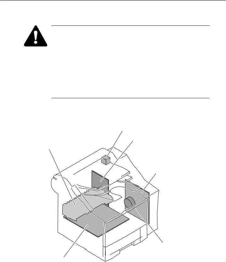
The temperatures of the parts shown below become more than 50°C during operation. Be Careful not to burn yourself on any of these parts during servicing.
Read motor
Power supply unit (heatsink)
Fixing ass'y
SCNT board (heatsink)
Main motor
ECNT board (heatsink)
Figure 1-2 High Temperature Parts
1-3

FAX-L1000 Chapter 1: Safety and Precautions
1.3 Fire
Danger
Do not throw the lithium battery or the toner cartridge into fire.
Lithium battery
The lithium battery contain lithium, organic solvents and other combustible substances. If the lithium battery is thrown into fires, it may rupture and burn fiercely.
Toner
The toner in the toner cartridge contains flammable substances.
The danger of fire exists with toner scattered around in a tightly-closed room.
Follow local applicable laws and regulations when disposing of the lithium battery or the toner cartridge.
1-4

FAX-L1000 Chapter 1: Safety and Precautions
This page intentionally left blank
1-5

FAX-L1000 Chapter 1: Safety and Precautions
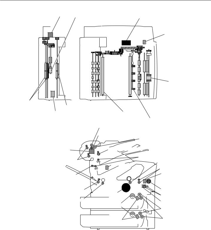
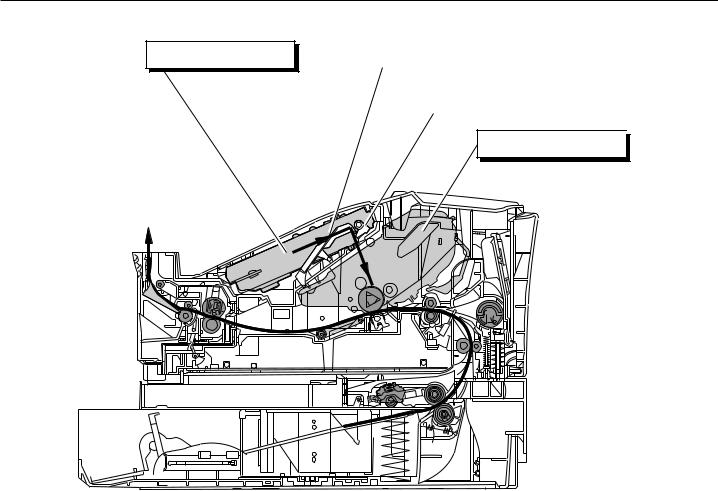
1.4 Moving and Rotating Parts
Precautions
To prevent accidents involving moving or rotating parts during servicing, that disconnect the power cord before starting disassembly.
When you must service the fax with the power cord plugged in, you must not wear bracelets, necklaces, neckties, or other objects. Also, take care to prevent hair and other articles of clothing from becoming entangled.
The fax is provided with a protection function which stops moving and rotating parts in the printer, when the printer cover is opened during operation. However, if these sensors have to be moved when carrying out servicing with the power cord plugged in, moving and rotating parts will operate even with these covers open.
Since this fax does not have a sensor to detect when the right cover or left cover is removed, even if you open the front cover or rear cover while this fax
is operating, the gears and rollers continue to move.
NOTE
1-6
FAX-L1000 Chapter 1: Safety and Precautions
Read motor |
Separation roller (Upper) |
Main motor |
Multi-purpose tray pickup solenoid
Multi-purpose tray |
pickup roller |
Document feed roller
Document eject roller |
|
||
DC motor |
Pressure roller |
|
|
|
|
Cassette pickup roller |
|
|
Separation roller (Upper) |
|
|
|
Separation roller (Lower) |
Pick-up roller |
|
|
|
||
Read motor |
Document eject roller |
||
Document feed roller |
|
Face-down delivery roller |
|
|
Transfer charging roller |
||
|
Solenoid |
||
|
Pre-transfer roller |
||
|
|
||
Paper feed roller |
|
Multi-purpose tray |
|
|
pickup solenoid |
||
|
|
Multi-porpose tray |
|
Fixing eject roller |
|
pickup roller |
|
Main motor |
Feed roller |
||
|
|||
Pressure roller |
|
Feed roller clutch |
|
|
Cassette pickup roller |
||
|
|
||
|
|
Cassette feed roller |
|
|
|
Cassette separation |
|
|
Cassette pickup solenoid |
roller |
|
Figure 1-3 Moving and Rotating Parts
1-7
FAX-L1000 Chapter 1: Safety and Precautions
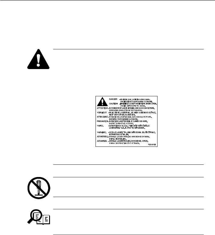
1.5 Laser Beams
This fax is a Class 1 Laser Product as defined in the EN60825 (IEC825) Radiation Safety of laser products, equipment classification, requirements and user’s guide. This means that this product uses lasers that do not radiate dangerous laser beam and conforms to the regulations because the laser beam does not affect the user during operations.
Warning
If the LASER light gets in your eyes, it will damage the retina. Figure 1-4 is a LASER beam warning label which is placed on the LASER/scanner unit. Always remain within the contents of this manual when servicing, and do not carry out any other maintenance. Within the range of service work in this manual, you will not be exposed to dangerous LASER light.
Figure 1-4 LASER beam warning label
Disassembly Prohibited
Never disassemble or alter the printer section laser/scanner unit. There is no servicing that requires you to disassemble the laser/scanner unit.
Safety Mechanism
This fax is designed with a structure such that the laser shutter only opens
when the toner cartridge has been inserted into this fax. This keeps the laser
NOTE
from operating other than during normal operations.
1-8
FAX-L1000 Chapter 1: Safety and Precautions
Laser/Scanner unit
Laser light
Laser shutter
FX6 toner cartridge 

Figure 1-5 Laser Shutter
1-9
FAX-L1000 Chapter 1: Safety and Precautions
2.DANGER TO EQUIPMENT
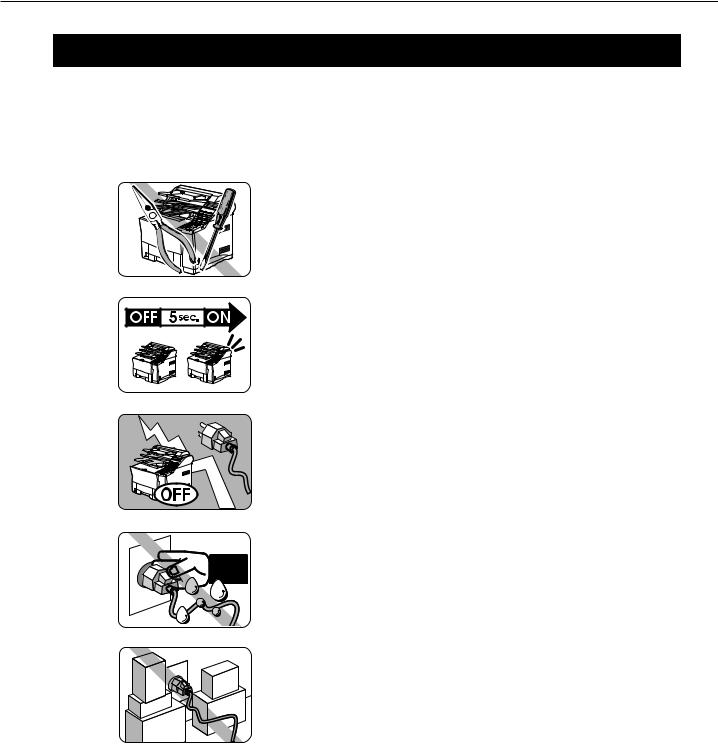
2.1Handling the FAX
General Precautions
TO AVOID SERIOUS INJURY, NEVER DISASSEMBLE
THE FAX. EXPOSED POWER POINTS INSIDE THE FAX CAN CAUSE ELECTRICAL SHOCK IF YOU TOUCH THEM.
After you unplug the fax unit, always wait at least 5 seconds before you plug it in again. Always unplug before you move the fax.
During electrical storms, disconnect the plug from the power outlet. The fax can hold documents in the memory for up to 12 hours.
Before you attach or remove the plug from the power outlet, make sure your hands are dry.
Do not stack boxes or furniture around the power outlet.
Keep the area open so you can reach the outlet quickly. If you notice anything unusual (smoke, strange odors, noises) around the fax, turn the fax off immediately and unplug it. Call for service.
Figure 1-6 Precautions 1
1-10
Loading...