


 Loading...
LBP7750C/5460 Series
Service Manual
Product Description
Technical Reference
Disassembly and Assembly
Maintenance and Inspection
Troubleshooting
Appendix
1 |
2 |
3 |
4 |
5 |
Application
This manual has been issued by Canon Inc. for qualified persons to learn technical theory, installation, maintenance, and repair of products. This manual covers all localities where the products are sold. For this reason, there may be information in this manual that does not apply to your locality.
Corrections
This manual may contain technical inaccuracies or typographical errors due to improvements or changes in products. When changes occur in applicable products or in the contents of this manual, Canon will release technical information as the need arises. In the event of major changes in the contents of this manual over a long or short period, Canon will issue a new edition of this manual.
The following paragraph does not apply to any countries where such provisions are inconsistent with local law.
Trademarks
The product names and company names used in this manual are the registered trademarks of the individual companies.
Copyright
This manual is copyrighted with all rights reserved. Under the copyright laws, this manual may not be copied, reproduced or translated into another language, in whole or in part, without the written consent of Canon Inc.
(C) CANON INC. 2009
Caution
Use of this manual should be strictly supervised to avoid disclosure of confidential information.

Explanation of Symbols
The following symbols are used throughout this Service Manual.
Symbols Explanation
Used to show permission.
Used to show prohibition.
The following rules apply throughout this Service Manual:
1.Each chapter contains sections explaining the purpose of specific functions and the relationship between electrical and mechanical systems with reference to the timing of operation.
In the diagrams,  represents the path of mechanical drive; where a signal name accompanies the symbol, the arrow
  indicates the direction of the electric signal.
The expression "turn on the power" means flipping on the power switch, closing the front door, and closing the delivery unit door, which results in supplying the machine with power.
2.In the digital circuits, '1' is used to indicate that the voltage level of a given signal is "High", while '0' is used to indicate "Low". (The voltage value, however, differs from circuit to circuit.) In addition, the asterisk (*) as in "DRMD*" indicates that the DRMD signal goes on when '0'.
In practically all cases, the internal mechanisms of a microprocessor cannot be checked in the field. Therefore, the operations of the microprocessors used in the machines
are not discussed: they are explained in terms of from sensors to the input of the DC controller PCB and from the output of the DC controller PCB to the loads.
The descriptions in this Service Manual are subject to change without notice for product improvement or other purposes, and major changes will be communicated in the form of
Service Information bulletins.
All service persons are expected to have a good understanding of the contents of this Service Manual and all relevant Service Information bulletins and be able to identify and isolate faults in the machine.
Contents
Operation Sequence---------------------------------------------------------- |
2-3 |
Overview------------------------------------------------------------------------------ |
2-3 |
Laser Exposure System------------------------------------------------------ |
2-4 |
1 Product Description
Characteristics------------------------------------------------------------------ |
1-2 |
System Configuration--------------------------------------------------------- |
1-2 |
System Configuration-------------------------------------------------------------- |
1-2 |
Product Specifications-------------------------------------------------------- |
1-3 |
Host Machine Specifications----------------------------------------------------- |
1-3 |
Detailed Specification--------------------------------------------------------- |
1-5 |
Printing Speed----------------------------------------------------------------------- |
1-5 |
Paper Type -------------------------------------------------------------------------- |
1-5 |
Paper Size---------------------------------------------------------------------------- |
1-6 |
Parts Name---------------------------------------------------------------------- |
1-7 |
External View------------------------------------------------------------------------ |
1-7 |
Cross Section View---------------------------------------------------------------- |
1-8 |
Operation------------------------------------------------------------------------ |
1-9 |
Control Panel------------------------------------------------------------------------ |
1-9 |
Job Menu---------------------------------------------------------------------------- |
1-11 |
Setup Menu------------------------------------------------------------------------- |
1-11 |
Utility Menu-------------------------------------------------------------------------- |
1-16 |
Reset Menu------------------------------------------------------------------------- |
1-17 |
Select Feeder Menu-------------------------------------------------------------- |
1-17 |
Safety Precautions---------------------------------------------------------- |
1-18 |
Overview------------------------------------------------------------------------------ |
2-4 |
Detecting a Failure in the Optical Assembly--------------------------------- |
2-4 |
Safety---------------------------------------------------------------------------------- |
2-4 |
Image Formation System---------------------------------------------------- |
2-5 |
Overview------------------------------------------------------------------------------ |
2-5 |
Image Formation Process-------------------------------------------------------- |
2-5 |
Controls------------------------------------------------------------------------------- |
2-9 |
Cartridge----------------------------------------------------------------------------- |
2-12 |
ITB Unit------------------------------------------------------------------------------ |
2-14 |
Fixing System----------------------------------------------------------------- |
2-17 |
Overview----------------------------------------------------------------------------- |
2-17 |
Various Controls------------------------------------------------------------------- |
2-17 |
Pickup Feeding System---------------------------------------------------- |
2-21 |
Overview----------------------------------------------------------------------------- |
2-21 |
Pickup Feeding Assembly------------------------------------------------------- |
2-22 |
Fixing/Delivery Assembly-------------------------------------------------------- |
2-28 |
Duplex Assembly------------------------------------------------------------------ |
2-29 |
Jam Detection---------------------------------------------------------------------- |
2-30 |
Controller System------------------------------------------------------------ |
2-32 |
Overview----------------------------------------------------------------------------- |
2-32 |
DC Controller PCB---------------------------------------------------------------- |
2-32 |
Low-voltage Power Supply------------------------------------------------------ |
2-35 |
Embedded RDS-------------------------------------------------------------- |
2-37 |
Laser Safety------------------------------------------------------------------------ |
1-18 |
Overview----------------------------------------------------------------------------- |
2-37 |
CDRH Regulation----------------------------------------------------------------- |
1-18 |
Settings Procedures-------------------------------------------------------------- |
2-37 |
Toner Safety------------------------------------------------------------------------ |
1-18 |
FAQ----------------------------------------------------------------------------------- |
2-40 |
How to Handle the Laser Scanner Unit-------------------------------------- |
1-18 |
Troubleshooting Guide----------------------------------------------------------- |
2-41 |
Points to Note when Replacing/Discarding a Lithium Battery---------- |
1-19 |
Service Cautions------------------------------------------------------------------- |
2-43 |
Points to Note when Performing Disassembly/Assembly--------------- |
1-19 |
3 Disassembly and Assembly |
|
2 Technical Reference |
|
|
|
|
Introduction---------------------------------------------------------------------- |
3-2 |
|
Basic Configuration----------------------------------------------------------- |
2-2 |
Points to Note During Disassembly and Assembly------------------------ |
3-2 |
Functional Configuration---------------------------------------------------------- |
2-2 |
Lay Out Drawing-------------------------------------------------------------------- |
3-3 |
External-related Issues------------------------------------------------------- |
3-9 |
Removing Left Cover-------------------------------------------------------------- |
3-9 |
Removing Rear Cover------------------------------------------------------------- |
3-9 |
Removing Right Rear Cover---------------------------------------------------- |
3-10 |
Removing the Control Panel Unit Right Cover----------------------------- |
3-10 |
Removing the Control Panel Unit Left Cover------------------------------- |
3-11 |
Removing Upper Front Cover Unit-------------------------------------------- |
3-11 |
Removing Control Panel Unit--------------------------------------------------- |
3-13 |
Removing Upper Rear Cover--------------------------------------------------- |
3-14 |
Removing the Front Cover Unit------------------------------------------------ |
3-14 |
Removing Front Right Cover--------------------------------------------------- |
3-15 |
Removing the Right Cover Unit------------------------------------------------ |
3-16 |
Main Units--------------------------------------------------------------------- |
3-17 |
Removing Secondary Transfer Unit------------------------------------------- |
3-17 |
Removing ITB Unit---------------------------------------------------------------- |
3-17 |
Removing Fixing Assembly----------------------------------------------------- |
3-18 |
Removing Waste Toner Container-------------------------------------------- |
3-19 |
Removing Waste Toner Full Sensor Unit------------------------------------ |
3-19 |
Removing Waste Toner Feed Motor Unit------------------------------------ |
3-20 |
Removing Registration Unit----------------------------------------------------- |
3-21 |
Removing Color Displacement/Density Sensor Unit--------------------- |
3-23 |
Removing Lifter Drive Unit------------------------------------------------------ |
3-24 |
Removing Laser Scanner Unit------------------------------------------------- |
3-25 |
Removing Cassette Pickup Drive Unit--------------------------------------- |
3-29 |
Removing Cassette Pickup Unit----------------------------------------------- |
3-31 |
Removing the Main Drive Unit------------------------------------------------- |
3-32 |
Removing the Fixing Drive Unit------------------------------------------------ |
3-35 |
Removing the Delivery Unit----------------------------------------------------- |
3-36 |
Removing the Duplex Drive Unit----------------------------------------------- |
3-38 |
Removing the Duplex Feed Roller Unit-------------------------------------- |
3-39 |
Removing the Multi-purpose Tray Pickup Unit----------------------------- |
3-40 |
Main Parts--------------------------------------------------------------------- |
3-43 |
Removing the Cassette Pickup Roller---------------------------------------- |
3-43 |
Removing the Cassette Separation Roller Assembly-------------------- |
3-44 |
Removing the Power Fan------------------------------------------------------- |
3-44 |
Removing the Fan Unit----------------------------------------------------------- |
3-46 |
|
Removing the Developing Disengagement Motor------------------------- |
3-47 |
|
Removing the Secondary Transfer Outer Roller Unit--------------------- |
3-48 |
|
Removing the Pickup Motor---------------------------------------------------- |
3-49 |
|
Removing the Drum Motor 1---------------------------------------------------- |
3-50 |
|
Removing the Drum Motor 2---------------------------------------------------- |
3-50 |
|
Removing the Drum Motor 3---------------------------------------------------- |
3-51 |
|
Removing the Fixing Motor----------------------------------------------------- |
3-51 |
|
Removing the Delivery Fan----------------------------------------------------- |
3-52 |
|
Removing the Cartridge Fan---------------------------------------------------- |
3-53 |
|
Removing the Multi-purpose Tray Pickup Roller--------------------------- |
3-54 |
|
Removing the Multi-purpose Tray Separation Pad------------------------ |
3-55 |
|
Removing the Controller Fan--------------------------------------------------- |
3-56 |
|
PCB-related Issures--------------------------------------------------------- |
3-58 |
|
Removing the ICB PCB---------------------------------------------------------- |
3-58 |
|
Removing the Main Controller PCB------------------------------------------- |
3-58 |
|
Removing the Low Voltage Power Unit-------------------------------------- |
3-60 |
|
Removing the DC Controller PCB--------------------------------------------- |
3-62 |
|
Removing the Lower High Voltage Power Supply PCB------------------ |
3-63 |
|
Removing the Upper High Voltage Power Supply PCB------------------ |
3-65 |
|
Removing the Environment Sensor------------------------------------------- |
3-66 |
4 |
Maintenance and Inspection |
|
|
Periodically Replaced Parts------------------------------------------------- |
4-2 |
|
Periodically Replaced Parts------------------------------------------------------ |
4-2 |
|
Consumable Parts------------------------------------------------------------- |
4-2 |
|
Consumable Parts Replaced by Users--------------------------------------- |
4-2 |
|
Consumable Parts Replaced by Service Engineers----------------------- |
4-2 |
|
Periodical Service------------------------------------------------------------- |
4-2 |
|
Periodical Service------------------------------------------------------------------ |
4-2 |
|
Cleaning-------------------------------------------------------------------------- |
4-3 |
|
Cleaning Item------------------------------------------------------------------------ |
4-3 |
5 |
Troubleshooting |
|
|
Corrective Actions------------------------------------------------------------- |
5-2 |
|
Image Failure------------------------------------------------------------------------ |
5-2 |
|
Standard/Adjustment--------------------------------------------------------- |
5-9 |
Test Print------------------------------------------------------------------------------ |
5-9 |
Adjustment of the Image Formation System--------------------------------- |
5-9 |
Adjustment of the Fixing Assembly------------------------------------------- |
5-10 |
Adjustment of Electrical Parts-------------------------------------------------- |
5-11 |
Outline of Electrical Components---------------------------------------- |
5-12 |
Sensor-------------------------------------------------------------------------------- |
5-12 |
Motor---------------------------------------------------------------------------------- |
5-13 |
Clutch/Solenoid-------------------------------------------------------------------- |
5-13 |
Fan------------------------------------------------------------------------------------ |
5-14 |
LED/Heater/Thermistor/Switch------------------------------------------------- |
5-14 |
PCB----------------------------------------------------------------------------------- |
5-15 |
Connector Layout Drawing------------------------------------------------ |
5-17 |
Connector List---------------------------------------------------------------------- |
5-17 |
Service Tools------------------------------------------------------------------ |
5-20 |
Standard Tools--------------------------------------------------------------------- |
5-20 |
List of Solvents/Greases--------------------------------------------------------- |
5-20 |
Error Code--------------------------------------------------------------------- |
5-21 |
Error Code Details----------------------------------------------------------------- |
5-21 |
Jam Code---------------------------------------------------------------------------- |
5-24 |
Alarm Code------------------------------------------------------------------------- |
5-25 |
Version Up--------------------------------------------------------------------- |
5-26 |
Overview----------------------------------------------------------------------------- |
5-26 |
Preparation-------------------------------------------------------------------------- |
5-26 |
Downloading the System Software------------------------------------------- |
5-27 |
Service Mode----------------------------------------------------------------- |
5-30 |
Service Mode List----------------------------------------------------------------- |
5-30 |
Special Administrator Mode----------------------------------------------- |
5-34 |
6 Appendix
General Timing Chart--------------------------------------------------------- |
6-2 |
General Circuit Diagram----------------------------------------------------- |
6-3 |
General Circuit Diagram (1/2)--------------------------------------------------- |
6-3 |
General Circuit Diagram (2/2)--------------------------------------------------- |
6-4 |
Signal Input/Output List------------------------------------------------------ |
6-5 |

1 |
Product Description |
■Characteristics |
■System Configuration ■Product Specifications ■Detailed Specification
■Parts Name ■Operation ■Safety Precautions
1 Product Description

1 Product Description > System Configuration > System Configuration
Characteristics
● High-Speed Color Printer
This machine is a high-speed color printer, realizing a speed of approximately 30 pages per minute in full-color printing with A4 vertical paper.
● Introducing Intermediate Transfer Method (ITB)
This machine introduced an intermediate transfer method, in which 4-color toner images are transferred into an intermediate transfer belt (ITB) and then simultaneously transferred into a printing sheet. This method enabled to realize stable color printing in various types of paper without receiving impact of paper at the time of primary transfer.
● Automatic Duplex Printing
This machine supports automatic duplex printing as standard function.
1-2
System Configuration
System Configuration
[2] |
[1] |
[3]
[4]
[5] |
F-1-1 |
|
Option |
Description |
[1] |
Paper Feeder |
1 extra cassette can be installed. |
|
PF-723 |
|
[2] |
Hard Disk Kit |
Hard disk with 40GB |
|
HD-14 |
|
[3] |
Extended RAM |
3 types are provided; 128MB, 256MB, and 512MB |
|
RD-128/256/512MW |
|
[4] |
Control ROM |
Emulation modes and fonts are contained. |
|
CR-HIX |
|
[5] |
Intelligent Controller |
Installation of the MEAP-Lite application, which is |
|
NB-J2 |
created with Java language, enables customization of |
|
|
printer function. SMS is mounted so that application |
|
|
can be controlled by a browser. |
[6] |
Self-contained Wireless Print Server |
This enables wireless LAN communication and |
|
NB-W2 |
security supported. |
|
|
|
T-1-1
1-2
1 Product Description > System Configuration > System Configuration

1 Product Description > Product Specifications > Host Machine Specifications
Product Specifications
Item |
Function / Method |
Installation of the host machine |
Desktop page printer |
Photoreceptor |
OPC drum |
Charging method |
Roller charging |
|
|
Exposure method |
Laser exposure |
|
|
Developing method |
Contact development |
Transfer method |
Intermediate transfer (ITB) |
Transfer (primary transfer) method |
Transfer belt |
|
|
Transfer (secondary transfer) method |
Transfer roller |
|
|
Separation method |
Curvature separation |
Feeding method |
Cassette / manual feeding |
Cassette feeding method |
Simple retard method |
Manual tray feeding method |
Pad separation method |
|
|
Drum cleaning method |
Blade |
Transfer cleaning method |
Blade |
Fixing method |
On-demand fixing |
Delivery method |
Face-down |
|
|
Contrast adjustment function |
Automatic |
|
|
Toner level detection |
Enabled (Optical detection) |
Toner type |
Nonmagnetic 1-component toner |
Toner supply method |
Replacement of the cartridge |
|
|
Warm-up time |
Less than approx. 60 sec. when the power is turned on |
|
(Room temperature: 20 degree C) |
Print quality guaranteed range |
Excluding 5.0mm from leading edge, trailing edge and |
|
right and left edge (10mm for envelope) |
Image gradation |
16 levels |
Print resolution |
600dpi x 600dpi |
First print time |
Black and white printing: 10.2 seconds or less |
|
Color printing: 10.4 seconds or less |
|
|
1-3
Item |
|
Function / Method |
Paper size for the cassette |
Standard sizes: |
|
|
A4, B5, A5, Letter, Executive, 16K |
|
|
Custom paper sizes: |
|
|
• |
Portrait orientation (when the short edges of the |
|
|
paper are parallel to the front side of the printer): |
|
|
Short edges 8.27 to 8.50 in.(210.0 to 215.9 mm); |
|
• |
Long edges 8.27 to 8.50 in.(210.0 to 215.9 mm) |
|
Landscape orientation (when the long edges of the |
|
|
|
paper are parallel to the front side of the printer): |
|
|
Short edges 5.85 to 8.50 in.(148.0 to 215.9 mm); |
|
|
Long edges 8.27 to 11.69 in. (210.0 to 297.0 mm) |
Paper size for the multi-purpose tray |
Standard sizes: |
|
|
A4, B5, A5, Legal, Letter, Executive, Statement, |
|
|
Foolscap, 16K, Envelope DL, Envelope No.10, |
|
|
Envelope ISO-C5, Envelope ISO-B5, Envelope |
|
|
Monarch |
|
|
Custom paper sizes: |
|
|
• |
Portrait orientation (when the short edges of the |
|
|
paper are parallel to the front side of the printer): |
|
|
Short edges 8.27 to 8.50 in.(210.0 to 215.9 mm); |
|
• |
Long edges 8.27 to 8.50 in. (210.0 to 215.9 mm) |
|
Landscape orientation (when the long edges of the |
|
|
|
paper are parallel to the front side of the printer): |
|
|
Short edges 3.87 to 8.50 in.(98.4 to 215.9 mm); |
|
|
Long edges 5.83 to 14.00 in. (148.0 to 355.6 mm) |
Paper type for the cassette |
Plain paper*1 (60 - 105g/m2), Thick paper (106 - 163g/ |
|
|
m2), Colored paper, Coated paper |
|
|
*1: Recycled paper can be used as plain paper. |
|
Paper type for the multi-purpose tray |
Plain paper*2 (60 - 105g/m2), Thick paper (106 - 163g/ |
|
|
m2), Label, Coated paper (100 - 220g/m2), Postcard, |
|
|
Envelope, OHP film (only for monochrome printing) |
|
|
Paper weight: 60 - 216g/m2 (Excl. coated paper) |
|
|
: 105 - 220g/m2 (Coated paper) |
|
|
*2: Recycled paper can be used as plain paper. |
|
Paper type for duplex printing |
Plain paper*3 (60 - 105g/m2), Thick paper (106 - 163g/ |
|
|
m2), Colored paper, Coated paper (120 - 220g/m2) |
|
|
*3: Recycled paper can be used as plain paper. |
|
Capacity of the cassette |
Cassette 1: Approx.250 sheets (80g/m2 paper) |
|
|
Cassette 2 (Option): Approx.500 sheets (80g/m2 paper) |
|
Capacity of the multi-purpose tray |
Cassette 1: Approx.100 sheets (80g/m2 paper) |
|
Duplex method |
Through-pass method |
|
Stack capacity of the delivery tray |
Approx.200 sheets (Plan paper, 80g/m2) |
|
Memory capacity |
256MB (Max. 768MB) |
|
|
|
|
HD capacity |
40GB (When an option is installed) |
|
|
|
1-3 |
1 Product Description > Product Specifications > Host Machine Specifications

|
1 |
Product Description > Product Specifications > Host Machine Specifications |
|||
|
|
|
|
1-4 |
|
|
|
|
|
|
|
|
|
Item |
|
Function / Method |
|
|
Automatic gradation correction |
Enabled |
|
||
|
Temperature range in the use environment |
10 - 30 degree C |
|
||
|
Humidity range in the use environment |
10 - 80%RH |
|
||
|
Operation noise |
Lwad (declared A-weighted sound power level |
|
||
|
|
|
(1B=10dB)) |
|
|
|
|
|
• |
During standby: 5B or less |
|
|
|
|
• |
During operation: 7B or less |
|
|
|
|
Sound pressure level (bysatander position) |
|
|
|
|
|
• |
During standby: 50dB or less |
|
|
|
|
• |
During operation: 53dB(A) or less |
|
|
Rated power voltage |
100V ± 10%, 110-127V ± 10%, 220-240V ± 10% |
|
||
|
|
|
(50/60Hz ± 2Hz) |
|
|
|
Maximum power consumption |
Less than 1305W |
|
||
|
Power consumption |
At standby: Approx. 47W |
|
||
|
|
|
Average during operation: Approx. 573W |
|
|
|
|
|
|
|
|
|
|
|
Average during deep sleep mode: Approx. 1.8W |
|
|
|
Dimension |
517 (W) x 530 (D) x 374 (H) mm |
|
||
|
Weight |
Approx. 31.0kg (Excl. cartridge) |
|
||
|
|
|
|
T-1-2 |
|
1-4
1 Product Description > Product Specifications > Host Machine Specifications
1 Product Description > Detailed Specification > Paper Type
Detailed Specification
Printing Speed
Printing speed of the LBP7750C/5460 machine is shown below. The machine provides the
|
|
Cassette 1 pickup |
Multi-purpose tray |
Cassette 2 pickup |
||||
|
|
|
|
|
|
(option) |
||
|
|
1-sided |
2-sided |
1-sided |
2-sided |
1-sided |
2-sided |
|
|
A4 vertical |
30.0 |
27.6 |
26.9 |
7.5 |
30.0 |
13.8 |
|
Plain paper |
A5 vertical |
31.0 |
- |
28.1 |
- |
31.0 |
- |
|
B5 vertical |
31.0 |
28.9 |
28.1 |
7.7 |
31.0 |
14.4 |
||
(60 to 105 g/m2) |
||||||||
LGL |
- |
- |
23.4 |
6.9 |
25.8 |
7.0 |
||
|
||||||||
|
LTR vertical |
31.0 |
28.9 |
28.1 |
7.7 |
31.0 |
14.4 |
|
|
EXE vertical |
31.0 |
28.9 |
28.1 |
7.7 |
31.0 |
14.4 |
|
|
A4 vertical |
15.0 |
13.7 |
15.0 |
3.7 |
15.0 |
6.8 |
|
Heavy paper |
A5 vertical |
15.8 |
- |
15.7 |
- |
15.8 |
- |
|
B5 vertical |
15.8 |
14.4 |
15.7 |
3.8 |
15.8 |
7.2 |
||
(106 to 120 g/m2) |
||||||||
Rough paper |
LGL |
- |
- |
12.8 |
3.4 |
12.8 |
3.5 |
|
(75 to 90 g/m2) |
|
|
|
|
|
|
|
|
LTR vertical |
15.8 |
14.4 |
15.7 |
3.8 |
15.8 |
7.2 |
||
|
||||||||
|
EXE vertical |
15.8 |
14.4 |
15.7 |
3.8 |
15.8 |
7.2 |
|
|
A4 vertical |
- |
- |
9.5 |
2.5 |
- |
- |
|
|
A5 vertical |
- |
- |
10.0 |
- |
- |
- |
|
Heavy paper |
B5 vertical |
- |
- |
10.0 |
2.5 |
- |
- |
|
(121 to 216 g/m2) |
LGL |
- |
- |
8.2 |
2.3 |
- |
- |
|
|
LTR vertical |
- |
- |
10.0 |
2.5 |
- |
- |
|
|
EXE vertical |
- |
- |
10.0 |
2.5 |
- |
- |
|
Label paper |
|
- |
- |
15.0 |
- |
- |
- |
|
Transparency film |
|
- |
- |
4.0 |
- |
- |
- |
|
Envelope |
|
- |
- |
15.7 |
- |
- |
- |
|
Postcard |
|
- |
- |
10.0 |
- |
10.0 |
- |
|
|
|
|
|
|
|
|
|
|
*1: 2 pages = 1 sheet (2 sided front and back page) |
|
|
|
T-1-3 |
||||
1-5
Paper Type
|
|
|
|
Setup Menu |
|
Paper Source |
|
|||
|
|
Paper Type |
|
[Cassette N (N = 1, 2) |
Multi-purpose |
Cassette 1 |
Cassette 2 |
|||
|
|
|
|
Type] |
|
tray |
|
(Optional) |
||
|
|
|
|
|
|
|
||||
|
|
16.0 to 19.8 lb Bond |
[Plain Paper L] |
*2 |
● |
|
● |
● |
||
Plain |
|
(60 to 74 g/m2) |
|
|
|
|||||
*1 |
|
|
[Plain Paper] |
|
|
|
|
|
||
paper |
18.6 to 27.9 lb Bond |
|
|
|
|
|
||||
|
(Default) |
*2*3 |
|
● |
|
● |
● |
|||
|
|
2 |
|
|
|
|
||||
|
|
(70 to 105 g/m |
) |
[Rough Paper]*6 |
|
|
|
|
||
|
|
26.6 lb Bond to 44.4 |
[Heavy Paper 1]*3*4 |
|
|
|
|
|||
|
|
lb Cover (100 to 120 |
● |
|
● |
● |
||||
|
|
g/m2) |
|
|
|
|
|
|
|
|
Heavy |
30.6 lb Bond to 60.3 |
[Heavy Paper 2]*4 |
|
|
|
|
||||
Paper |
lb Cover (115 to 163 |
○ |
|
○ |
○ |
|||||
|
|
g/m2) |
|
|
|
|
|
|
|
|
|
|
60.4 to 65.1 lb Cover |
[Heavy Paper 2] |
○ |
|
- |
○ |
|||
|
|
(164 to 176 g/m2) |
|
|||||||
Transparency |
|
[Transparencies] |
○ |
|
- |
- |
||||
(black-and-white printing only) |
|
|||||||||
Label |
|
|
|
[Label] |
|
|
○ |
|
- |
- |
Envelope |
|
[Envelope] |
|
○ |
|
- |
- |
|||
*1 Recycled paper can be used as plain paper.
*2 If you want to print paper of 18.6 to 19.8 lb Bond (70 to 74 g/m2), you can specify either of
[Plain Paper] or [Plain Paper L].*5
*3 If you want to print paper of 26.6 to 27.9 lb Bond (100 to 105 g/m2), you can specify either of [Plain Paper] or [Heavy Paper1].*5
*4 If you want to print paper of 30.6 lb Bond to 44.4 lb Cover (115 to 120 g/m2), you can specify either of [Heavy Paper 1] or [Heavy Paper 2].*5
*5 If either setting causes the following problems etc., specify the other setting to print.
•Output paper curls.
•Residual images apperar on non-printed areas.
•The toner does not fix onto paper well, and the printing comes out faint.
*6 Specify [Rough Paper] for this item when a paper jam occurs or when you want to improve the fixation on printing coarse paper (19.9 to 23.9 lb Bond(75 to 90 g/m2)) with [Plain Paper] selected.
1-5
1 Product Description > Detailed Specification > Paper Type

1 Product Description > Detailed Specification > Paper Size
Paper Size
This printer supports the following paper sizes.
|
Paper Size |
|
|
Paper Source |
|
|
||
|
Multi-purpose |
|
|
Cassette 2 |
||||
|
(short edge x long edge) |
Cassette 1 |
||||||
|
tray |
|
(Optional) |
|||||
|
|
|
||||||
A4 (8.27 in. x 11.69 in. (210.0 mm x 297.0 mm)) |
● |
|
● |
● |
||||
B5 (7.17 in. x 10.12 in. (182.0 mm x 257.0 mm)) |
● |
|
● |
● |
||||
A5 (5.83 in. x 8.27 in. (148.0 mm x 210.0 mm)) |
○ |
|
○ |
○ |
||||
|
|
|
|
|
|
|||
Legal (8.50 in. x 14.00 in. (215.9 mm x 355.6 mm)) |
● |
|
- |
● |
||||
|
|
|
|
|
|
|||
Letter (8.50 in. x 11.00 in. (215.9 mm x 279.4 mm)) |
● |
|
● |
● |
||||
Executive (7.25 in. x 10.50 in. (184.2 mm x 266.7 mm)) |
● |
|
● |
● |
||||
Statement (5.50 in. x 8.50 in. (139.7 mm x 215.9 mm)) |
○ |
|
- |
- |
||||
|
|
|
|
|
|
|||
Foolscap (8.50 in. x 13.00 in. (215.9 mm x 330.2 mm)) |
● |
|
- |
● |
||||
|
|
|
|
|
|
|||
16K (7.68 in. x 10.63 in. (195.0 mm x 270.0 mm)) |
● |
|
● |
● |
||||
Custom paper size |
○ |
*5 |
|
○ |
*6 |
○ |
*6 |
|
Portrait*1 *3 |
|
|
|
|
||||
Custom paper size |
● |
*7 |
|
● |
*8 |
● |
*9 |
|
Landscape*2 *4 |
|
|
|
|
||||
|
Envelope Monarch |
○ |
|
- |
- |
|||
|
(3.87 in. x 7.50 in. (98.4 mm x 190.5 mm)) |
|
||||||
|
|
|
|
|
|
|
|
|
|
Envelope No.10 |
○ |
|
- |
- |
|||
|
(4.12 in. x 9.50 in. (104.7 mm x 241.3 mm)) |
|
||||||
|
|
|
|
|
|
|
|
|
Envelope |
Envelope DL |
○ |
|
- |
- |
|||
(4.33 in. x 8.66 in. (110.0 mm x 220.0 mm)) |
|
|||||||
|
Envelope ISO-C5 |
○ |
|
- |
- |
|||
|
(6.38 in. x 9.02 in. (162.0 mm x 229.0 mm)) |
|
||||||
|
|
|
|
|
|
|
|
|
|
Envelope ISO-B5 |
○ |
|
- |
- |
|||
|
(6.93 in. x 9.84 in. (176.0 mm x 250.0 mm)) |
|
||||||
|
|
|
|
|
|
|
|
|
|
|
|
|
|
|
|
|
|
|
|
|
|
|
|
|
|
T-1-5 |
*1 Portrait: The short edges of the paper are parallel to the front side of the printer. *2 Landscape: The long edges of the paper are parallel to the front side of the printer. *3 Can be loaded only when the UFR II printer driver is used.
*4 Automatic 2-sided printing can be performed on the custom size paper whose short edges are 7.17 to 8.50 in. (182.0 to 215.9 mm) and long edges are 10.12 to 11.69 in. (257.0 to 297.0 mm).
1-6
*5 The custom size paper whose short edges are 5.83 to 8.50 in. (148.0 to 215.9 mm) and long edges are 5.83 to 8.50 in. (148.0 to 215.9 mm) can be loaded.
*6 The custom size paper whose short edges are 8.27 to 8.50 in. (210.0 to 215.9 mm) and long edges are 8.27 to 8.50 in. (210.0 to 215.9 mm) can be loaded.
*7 The custom size paper whose short edges are 3.87 to 8.50 in. (98.4 to 215.9 mm) and long edges are 5.83 to 14.00 in. (148.0 to 355.6 mm) can be loaded.
*8 The custom size paper whose short edges are 5.83 to 8.50 in. (148.0 to 215.9 mm) and long edges are 8.27 to 11.69 in. (210.0 to 297.0 mm) can be loaded.
*9 The custom size paper whose short edges are 5.83 to 8.50 in. (148.5 to 215.9 mm) and long edges are 8.27 to 14.00 in. (210.0 to 355.6 mm) can be loaded.
1-6
1 Product Description > Detailed Specification > Paper Size

1 Product Description > Parts Name > External View > Back View of the Printer
Caution :
Be sure not to cover the vent with a wall or an article. If it is covered, the inside of the printer becomes hot, which may cause a fire.
External View
■
[4] [5]
[1]
[6]
1-7
■ Back View of the Printer
[1] |
[10] |
|
|
||
[2] |
|
|
[3] |
|
|
[4] |
|
|
[5] |
|
|
[6] |
[8] |
|
[7] |
||
|
[8] |
[9] |
[11]
[12]
|
|
|
[7] |
|
[2] |
|
[8] |
|
[3] |
|
[9] |
|
|
|
|
|
|
|
F-1-2 |
[1] |
Power switch |
[6] |
Right cover |
[2] |
Front cover |
[7] |
Vent |
[3] |
Cassette |
[8] |
Multi-purpose tray |
[4] |
Control Panel |
[9] |
Grip |
[5]Delivery tray
F-1-3
[1] |
Slot cover |
[8] |
Grip |
[2] |
USB connector |
[9] |
Rated voltage label |
[3] |
LAN connector |
[10] |
Vent |
[4] |
LNK/ACT lamp (green) |
[11] |
Grounding wire terminal |
[5] |
10/100 lamp (green) |
[12] |
Power cord slot |
[6]Hard disk slot
[7]Extended board slot
1-7
1 Product Description > Parts Name > External View > Back View of the Printer

1 Product Description > Parts Name > Cross Section View
■ Inside of the Printer
[2] [3] [4] [5]
[6] |
[7] |
[1] |
[8] |
|
F-1-4
[1]Waste toner container
[2]Y (Yellow) toner cartridge
[3]M (Magenta) toner cartridge
[4]C (Cyan) toner cartridge
[5]K (Black) toner cartridge
[6]Fixing assembly
[7]ITB (Intermediate Transfer Belt) unit
[8]Secondary transfer external roller
1-8
Cross Section View
|
|
[1] [2] |
[3] [4] [5] [6] [7] [8] |
|
|
|
[9] |
|
|
|
[10] |
|
|
|
[11] |
|
|
|
[12] |
|
|
|
[13] |
|
|
|
[14] |
|
|
|
[15] |
|
|
|
[16] |
[25] |
[24] |
[23] |
[22][21][20][19][18] [17] |
|
|
|
F-1-5 |
[1]ITB unit
[2]Primary transfer roller
[3]Delivery roller 2
[4]Duplex reverse roller
[5]Duplex flapper
[6]Delivery roller 1
[7]Pressure roller
[8]Fixing assembly
[9]Fixing sleeve unit
[10]Duplex feed roller
[11]Secondary transfer outer roller
[12]ITB drive roller
[13]Color displacement/density sensor
[14]OHT sensor
[15]Registration shutter
[16]Multi-purpose tray pickup roller
[17]Multi-purpose tray separation pad
[18]Duplex re-pickup roller
[19]Registration roller
[20]Feed roller
[21]Cassette separation roller
[22]Cassette pickup roller
[23]Photosensitive drum
[24]Toner cartridge
[25]Laser scanner unit
1-8
1 Product Description > Parts Name > Cross Section View

1 Product Description > Operation > Control Panel > Lamp |
|
|
|
|
|
||||
Operation |
|
|
|
|
■ |
|
|
|
|
|
|
|
|
|
|
No. |
Name |
|
Condition |
Control Panel |
|
|
|
[1] |
Online |
Lighting |
The printer is in the on-line condition (Print data can be |
||
|
|
|
|
|
|
|
(Green) |
|
received from the computer in this condition). |
The control panel consists of lamps and displays showing the printer condition and operation |
|
|
When the printer is placed in the sleep mode, the on-line lamp |
||||||
keys. |
|
|
|
|
|
|
|
|
lights off even if the printer is in the on-line condition. |
|
|
|
|
|
[4] |
Pickup origination |
Lighting |
The pickup assembly is selected. |
|
|
|
|
|
|
|
||||
|
|
|
|
|
|
|
display (Green) |
Flashing |
No paper is set and printing cannot be performed. |
|
|
|
|
|
|
|
|
||
[1] |
[2] |
[4] |
[5] |
[11] |
[13] |
[16] |
|
|
The pickup cassette is not installed. |
|
|
|
|
|
|
|
|
|
(When the multi-purpose tray is used, the lamp lights up even |
|
|
|
|
|
|
|
|
|
when no paper is set.) |
|
|
Job |
|
[6] |
Printable |
Lighting |
Printing can be performed. |
Cancel Job |
|
|
|
|
|
|
|
Online |
|
Utility |
Settings |
Power |
|
Flashing |
Preparation for printing or calibration is performed. |
|
|
|
|
||||
Feeder Selection |
|
|
|
[7] |
Message |
Lighting |
A trouble occurred and printing cannot be performed. |
|
|
Back |
|
||||
|
|
|
Main Power |
(Orange) |
|
(When the printer is placed in the sleep mode in the off- |
|
Ready Message |
|
|
|
|
|||
Job |
Reset |
|
|
|
|
line condition, the message lamp lights up even if no trouble |
|
|
|
|
|
|
|
|
occurs.) |
[8] HDD (Green)
[3] |
[6] |
[7] |
[8] |
[9] |
[10] |
[12] |
[14] |
[15] |
[17] |
[9] |
Job |
Lighting Data is being received. |
|
|
|
|
|
|
|
|
|
|
|
(Green) |
Data remains in the printer memory. |
|
|
|
F-1-6 |
|
Flashing Data processing is being performed. |
|
[1] |
Online indicator / key |
[10] |
Utility key |
|
||
[17] Main power |
Lighting The power is turned on. |
|||||
[2] |
Job confirmation / cancel key |
[11] |
Job key |
|||
(Green) |
|
|||||
[3] |
Pickup selection key |
[12] |
Return key |
|
||
|
T-1-6 |
|||||
[4] |
Pickup origination display lamp |
[13] |
OK key |
|
||
|
|
|||||
[5] |
Control panel display |
[14] |
Reset key |
|
|
|
[6] |
Printable lamp |
[15] |
Setup key |
|
|
|
[7] |
Message lamp |
[16] |
Control panel power switch (Sub power) |
|
|
|
[8] |
HDD lamp |
[17] |
Main power lamp (Green) |
|
|
[9]Job lamp
1-9
1 Product Description > Operation > Control Panel > Lamp

1 Product Description > Operation > Control Panel > Control Panel Key
■ Control Panel Key
No. |
Name |
|
Function |
[1] |
On-line |
The on-line and off-line conditions are switched. When the key lights up, |
|
|
|
the printer is placed in the on-line condition. When the key lights off, the |
|
|
|
printer is in the off-line condition. |
|
[2] |
Job |
On-line |
When this key is pressed in the condition where |
|
confirmation/cancel |
Off-line |
the job lamp lights up or flashes (data processing |
|
|
|
being performed/data being received), a list of |
|
|
|
jobs is displayed. You can select a job from the |
|
|
|
list and cancel it. |
|
|
Displaying the menu |
Not available |
[3] |
Pickup selection |
On-line |
The pickup selection menu is displayed. The |
|
|
|
setting of whether printing is performed from the |
|
|
Off-line |
|
|
|
pickup cassette or the multi-purpose tray, or that |
|
|
|
|
|
|
|
|
of the paper size is made. |
|
|
Displaying the menu |
Not available |
[10] |
Utility |
On-line |
The utility menu is displayed. Internal information |
|
|
|
such as current setting of the printer, etc., is |
|
|
|
printed. |
|
|
Off-line |
Not available |
|
|
Displaying the menu |
The printer returns to the previous level. |
|
|
|
|
[11] |
Job |
On-line |
The job menu is displayed. Operation of jobs |
|
|
|
saved in Secure Print or Box and various list of |
|
|
|
operation history are printed. |
|
|
Off-line |
Not available |
|
|
|
|
|
|
Displaying the menu |
An upper item in the same level is selected. |
|
|
|
When a numeric value is selected, the value |
|
|
|
increases. When the key is kept pressed, the |
|
|
|
speed of increasing the value becomes faster for |
|
|
|
some items. |
[12] |
Return |
On-line |
Not available |
|
|
|
|
|
|
Off-line |
|
|
|
|
|
|
|
Displaying the menu |
The printer returns to the previous level. |
[13] |
OK |
On-line |
Not available |
|
|
Off-line |
|
|
|
|
|
|
|
Displaying the menu |
The selected item is executed. Or, the printer |
|
|
|
goes to the next level. |
1-10
No. |
|
Name |
|
Function |
[14] |
Reset |
|
On-line |
The reset menu is displayed. Printer reset |
|
|
|
|
operation, discharging of printing data, and |
|
|
|
Off-line |
|
|
|
|
shutdown operation are performed. |
|
|
|
|
|
|
|
|
|
|
|
|
|
|
Displaying the menu |
The lower item in the same level is selected. |
|
|
|
|
When a numeric value is selected, the value |
|
|
|
|
decreases. When the key is kept pressed, the |
|
|
|
|
speed of decreasing the value becomes faster for |
|
|
|
|
some items. |
[15] |
Setup |
|
On-line |
The setup menu is displayed. The printing |
|
|
|
Off-line |
environment such as layout adjustment or |
|
|
|
enlargement/reduction can be set. |
|
|
|
|
|
|
|
|
|
Displaying the menu |
The selected item is executed. Or, the printer |
|
|
|
|
goes to the next level. |
[16] |
Power |
|
When "Sleep Mode" is set to other items than "Not used", the printer is |
|
|
|
|
placed in the sleep mode. |
|
|
|
|
|
T-1-7 |
1-10
1 Product Description > Operation > Control Panel > Control Panel Key

1 Product Description > Operation > Setup Menu > Control Menu Options
■
|
Setting |
Setting Value |
Job Menu |
Encrypted Print*1 |
- |
|
Secured Print*1 |
- |
|
Stored Job List*1 |
- |
|
Stored Job Print*1 |
- |
|
Job Print Log List |
- |
|
Stored Job Print Log*1 |
- |
|
Report Print Log |
- |
|
E-mail Print Log |
- |
|
|
|
T-1-8
• Items and setting values with "*1" may not be displayed depending on the model, presence/ absence of options, or contents of other setting items.
1-11
■
|
Setting |
|
Setting Value |
|
Power Save Mode |
[On]*, [Deep Sleep], [Off], [Panel Off] |
|||
Power Save in Error |
[On]*, [Off] |
|||
Power Save Time |
|
|
||
|
When not using a hard disk |
[1 minute]*, [5 minutes], [10 minutes], [15 minutes], |
||
|
[30 minutes], [60 minutes], [180 minutes] |
|||
|
|
|||
When using a hard disk |
[5 minutes]*, [10 minutes], [15 minutes], [30 minutes], |
|||
|
||||
|
[60 minutes], [180 minutes] |
|||
|
|
|||
|
|
|
|
|
Timer Settings |
|
|
||
|
|
|
||
|
Wake Up Timer |
[Off]*, [On] |
||
|
|
• |
When [AM/PM] is selected in [12/24 Hour Clock]: |
|
|
Wake Up Time |
• |
00:00:00 AM/PM to 11:59:59 AM/PM |
|
|
When [24 Hour] is selected in [12/24 Hour Clock]: |
|||
|
|
|||
|
|
|
00:00:00 to 23:59:59 |
|
|
Power Save Timer |
[Off]*, [On] |
||
|
|
• |
When [AM/PM] is selected in [12/24 Hour Clock]: |
|
Power Save Time |
• |
00:00:00 AM/PM to 11:59:59 AM/PM |
||
|
When [24 Hour] is selected in [12/24 Hour Clock]: |
|||
|
|
|||
|
|
|
00:00:00 to 23:59:59 |
|
|
|
|
||
|
Calibration Timer |
[Off]*, [On] |
||
|
|
• |
When [AM/PM] is selected in [12/24 Hour Clock]: |
|
|
Calibration Time |
• |
00:00:00 AM/PM to 11:59:59 AM/PM |
|
|
When [24 Hour] is selected in [12/24 Hour Clock]: |
|||
|
|
|||
|
|
|
00:00:00 to 23:59:59 |
|
Warning Step |
|
|
||
|
Check Toner |
[Continue Printing]*, [Stop Printing] |
||
Auto Error Skip |
[Off]*, [On] |
|||
Panel Language |
[English]*, [Español], [Français], [Italiano], [Deutsch] |
|||
Alarm |
|
[On]*, [Off] |
||
Show Warnings |
|
|
||
|
|
|
||
|
Check Toner |
[On]*, [Off] |
||
|
Check Waste Tnr Ctn |
[On]*, [Off] |
||
Cassette Empty |
[On]*, [Off] |
|||
|
||||
|
E-mail Trans. Error |
[On]*, [Off] |
||
1-11
1 Product Description > Operation > Setup Menu > Control Menu Options

1 Product Description > Operation > Setup Menu > Paper Source Menu Options
|
Setting |
|
Setting Value |
|
Date and Time |
|
|
||
|
|
|
||
|
Date Settings |
01/01/2001 to 31/12/2089 |
||
|
12/24 Hour Clock |
[AM/PM]*, [24 Hour] |
||
|
|
• |
When [AM/PM] is selected in [12/24 Hour Clock]: |
|
|
Time Settings |
• |
00:00:00 AM/PM to 11:59:59 AM/PM |
|
|
When [24 Hour] is selected in [12/24 Hour Clock]: |
|||
|
|
|||
|
|
|
00:00:00 to 23:59:59 |
|
|
|
|
||
|
[DST Settings]: [Off]*, [On] |
|||
|
|
|||
|
|
[Start Date and Time]: |
||
|
Daylight Saving Time |
<Month>, <Week>, <Day>, <Time Settings> |
||
|
|
[End Date and Time]: |
||
|
|
<Month>, <Week>, <Day>, <Time Settings> |
||
|
Time Zone |
GMT-12 to GMT+12 |
||
Hard Disk*1 |
[On]*, [Off] |
|||
Interrupt Print*1 |
[On]*, [Off] |
|||
Securing Time*1 |
[1 hour]*, [2 hours], [3 hours], [6 hours], [12 hours], |
|||
|
|
[24 hours] |
||
Secured Type*1 |
[Image]*, [PDL]*1 |
|||
RIP Once*1 |
[On]*, [Off] |
|||
Assure Job Log*1 |
[Off]*, [On] |
|||
PDL Select (PnP)*1 |
[UFR II]*, [PCL5C], [PCL6], [PS3]*1 |
|||
Adjust Screen |
|
|
||
|
Contrast |
-3 to 0* to +3 |
||
Backlight Brightness |
[Level 3]*, [Off], [Level 1], [Level 2] |
|||
|
||||
Animated Instruction |
[On]*, [Off] |
|||
Show Toner Gauge |
[On]*, [Off] |
|||
T-1-9
• Items and setting values with "*1" may not be displayed depending on the model, presence/ absence of options, or contents of other setting items.
• Setting values with "*" are factory setting values.
1-12
■ Paper Source Menu Options
|
Setting |
Setting Value |
MP Tray Paper Size |
[LTR]*, [LGL], [EXEC], [Mixed Sizes], [Custom Size], [Custom Size R], |
|
|
|
[ENV. ISOC5], [ENV. No.10], [ENV. C.G. No.8], |
|
|
[ENV. DL], [ENV. ISO-B5], [STMT], [FLSC], [16K], [A5], [B5], [A4] |
MP Tray Priority |
[Off]*, [On] |
|
Cassette 1 Size |
[LTR]*, [EXEC], [Mixed Sizes], [Custom Size], [Custom Size R], [16K], |
|
|
|
[A5], [B5],[A4] |
Cassette 2 Size*1 |
[Auto]*, [Custom Size], [Custom Size R], [16K], [Mixed Sizes] |
|
Standard Paper Size |
[LTR]*, [LGL], [EXEC], [ENV. ISO-C5], [ENV. No.10], [ENV. C.G. No.8], |
|
|
|
[ENV. DL], [ENV. ISO-B5], [STMT], [FLSC], [16K], [A5], [B5], [A4] |
Invalid Paper Tray |
[Off]*, [On] |
|
Auto Selection |
|
|
|
Multi-purpose Tray |
[On]*, [Off] |
|
Cassette 1 |
[On]*, [Off] |
|
Cassette 2*1 |
[On]*, [Off] |
Standard Paper Type |
[Plain Paper]*, [Plain Paper L], [Heavy Paper 1], [Heavy Paper 2], |
|
|
|
[Transparencies], [Envelope], [Coated Paper 1], [Coated Paper 2], |
|
|
[Coated Paper 3], [Label], [Rough Paper] |
MP Tray Paper Type |
[Mixed Types]*, [Plain Paper], [Plain Paper L], [Heavy Paper 1], |
|
|
|
[Heavy Paper 2], [Transparencies], [Envelope], [Coated Paper 1], |
|
|
[Coated Paper 2], [Coated Paper 3], [Label], [Rough Paper] |
Cassette 1 Type |
[Mixed Types]*, [Plain Paper], [Plain Paper L], [Heavy Paper 1], |
|
|
|
[Heavy Paper 2], [Coated Paper 1], [Coated Paper 2], [Rough Paper] |
|
|
|
Cassette 2 Type*1 |
[Mixed Types]*, [Plain Paper], [Plain Paper L], [Heavy Paper 1], |
|
|
|
[Heavy Paper 2], [Transparencies], [Coated Paper 1], [Coated Paper 2], |
|
|
[Coated Paper 3], [Label], [Rough Paper] |
Manual 2-Sided |
[1st Side]*, [2nd Side] |
|
2-Sided Printing |
[Off]*, [On] |
|
T-1-10
• Items and setting values with "*1" may not be displayed depending on the model, presence/ absence of options, or contents of other setting items.
• Setting values with "*" are factory setting values.
1-12
1 Product Description > Operation > Setup Menu > Paper Source Menu Options

1 Product Description > Operation > Setup Menu > Standard Network Menu Options
■ Standard Network Menu Options
|
Setting |
Setting Value |
|
TCP/IP Settings |
|
|
|
|
IP v.4 Settings |
IP Mode |
[Manual]*, [Auto] |
|
|
Protocol*1 |
Use DHCP: [Off]*, [On] |
|
|
|
Use BOOTP: [Off]*, [On] |
|
|
|
Use RARP: [Off]*, [On] |
|
|
IP Address Settings*1 |
IP Address: 0.0.0.0 |
|
|
|
Subnet Mask: 0.0.0.0 |
|
|
|
Gateway Address: 0.0.0.0 |
|
|
|
|
|
|
IP Address Range |
Reject Receive/Print: [Off]*, [On] |
|
|
|
Reject Address Set.*1: Reject IP address 1 to 8 |
|
|
|
Permit Receive/Print: [Off]*, [On] |
|
|
|
Permit Address Set.*1: Permit IP address 1 to 8 |
|
|
|
Reject Set/Browse: [Off]*, [On] |
|
|
|
Reject Address Set.*1: Reject IP address 1 to 8 |
|
|
|
Permit Set/Browse: [Off]*, [On] |
|
|
|
Permit Address Set.*1: Permit IP address 1 to 8 |
|
|
DNS |
Primary Address: 0.0.0.0 |
|
|
|
|
|
|
|
Secondary Address: 0.0.0.0 |
|
IP v.6 Settings |
|
IPv6: [Off]*, [On] |
|
WINS Resolution |
|
[Off]*, [On] |
|
ARP/PING |
|
[On]*, [Off] |
|
FTP |
FTP Print |
[Off]*, [On] |
|
|
FTP Settings |
[Off]*, [On] |
|
LPD Print |
|
[On]*, [Off] |
|
RAW Print |
|
[On]*, [Off] |
|
IPP Print |
|
[On]*, [Off] |
|
WSD |
WSD Print |
[On]*, [Off] |
|
|
WSD Browsing*1 |
[On]*, [Off] |
|
|
Multicast Discovery |
[On]*, [Off] |
|
HTTP |
|
[On]*, [Off] |
1-13
|
Setting |
Setting Value |
||
|
Proxy Settings*1 |
|
Proxy |
[Off]*, [On] |
|
|
|
Server Address |
- |
|
|
|
Port Number |
0 to 80* to 99999 |
|
|
|
Same Domain |
Do Not Use Proxy*, Use Proxy |
|
|
|
Proxy Authentication |
[Off]*, [On] |
|
|
|
User Name |
- |
|
|
|
Password |
- |
|
SNTP |
|
[Off]*, [On] |
|
|
Response |
|
[On]*, [Off] |
|
|
|
|
|
|
|
MAC Address |
|
Permit Receive |
[Off]*, [On] |
|
Settings |
|
|
|
|
|
Permit Address |
Permit MAC Add. 1 to Permit MAC Add. 50 |
|
|
|
|
||
|
|
|
Set.*1 |
|
|
NetWare Settings |
|
[NetWare]: [Off]*, [On] |
|
|
|
|
|
[Frame Type]: [Auto Detect]*, [Ethernet II], [Ethernet |
|
|
|
|
802.2], [Ethernet 802.3], [Ethernet SNAP] |
|
|
|
|
[Print Service]: [NDS PServer]*, [NPrinter], [Bindery |
|
|
|
|
PServer], [RPrinter] |
AppleTalk |
|
[Off]*, [On] |
||
SMB |
|
|
|
|
|
|
|
|
|
|
SMB Server |
|
[Off]*, [On] |
|
|
SMB*1 |
|
[Off]*, [On] |
|
SNMP v.1 |
|
[On]*, [Off] |
||
SNMP v.3 Settings |
|
|
||
|
SNMP v.3 |
|
[Off]*, [On] |
|
|
User Settings 1 to User Settings 5*1 |
Authent. Password |
||
|
|
|
|
Encryption Password |
Spooler*1 |
|
[Off]*, [On] |
||
Start Wait Time*1 |
|
0* to 300 |
||
Remote UI Settings |
|
|
||
|
|
|
|
|
|
Remote UI |
|
[On]*, [Off] |
|
|
SSL |
|
[Off]*, [On]*1 |
|
Ethernet Driver*1 |
|
|
||
|
Auto Detect |
|
[On]*, [Off] |
|
|
Communication Mode*1 |
[Half Duplex]*, [Full Duplex] |
||
|
Ethernet Type*1 |
|
[10 Base-T]*, [100 Base-TX] |
|
1-13
1 Product Description > Operation > Setup Menu > Standard Network Menu Options

1 Product Description > Operation > Setup Menu > Quality Menu Options
|
Setting |
Setting Value |
MAC Address*1 |
(Display only) |
|
E-Mail Print Set. |
|
|
|
POP3 Interval |
0* to 90 |
|
POP3 Receive |
[Off]*, [On] |
|
SMTP Receive |
[Off]*, [On] |
Initialize Network |
- |
|
T-1-11
• Items and setting values with "*1" may not be displayed depending on the model, presence/ absence of options, or contents of other setting items.
• Setting values with "*" are factory setting values.
■ Layout Menu Options
Setting |
Setting Value |
|
|
Copies |
1* to 9999 |
Offset Y |
-1.97 to 0.0* to 1.97 (in.) |
Offset X |
-1.97 to 0.0* to 1.97 (in.) |
Binding Location |
[Long Edge]*, [Short Edge] |
Gutter |
-1.97 to 0.0* to 1.97 (in.) |
Alternative Method |
[Off]*, [On] |
T-1-12
• Items and setting values with "*1" may not be displayed depending on the model, presence/ absence of options, or contents of other setting items.
• Setting values with "*" are factory setting values.
■ Quality Menu Options
Setting |
Setting Value |
Gradation Level |
[High 1]*, [High 2] |
Toner Save |
[Off]*, [On] |
Density: Cyan |
-8 to 0* to +7 |
Density: Magenta |
-8 to 0* to +7 |
Density: Yellow |
-8 to 0* to +7 |
Density: Black |
-8 to 0* to +7 |
Color Mode |
[Auto]*, [Color], [Black and White] |
1-14
|
Setting |
|
Setting Value |
Halftones |
|
|
|
|
|
|
|
|
B & W Halftones |
Text |
[Resolution]*, [Gradation], [Color Tone], |
|
|
|
[High Resolution], [Error Diffusion] |
|
|
Graphics |
[Gradation]*, [Color Tone], [High Resolution], |
|
|
|
[Error Diffusion], [Resolution] |
|
|
Image |
[Gradation]*, [Color Tone], [High Resolution], |
|
|
|
[Error Diffusion], [Resolution] |
|
Color Halftones |
Text |
[Resolution]*, [Gradation], [Color Tone], |
|
|
|
[High Resolution], [Error Diffusion] |
|
|
Graphics |
[Color Tone]*, [High Resolution], [Error Diffusion], |
|
|
|
[Resolution], [Gradation] |
|
|
Image |
[Color Tone]*, [High Resolution], [Error Diffusion], |
|
|
|
[Resolution], [Gradation] |
Gray Compensation |
|
|
|
|
|
|
|
|
Text |
|
[On]*, [Off] |
|
Graphics |
|
[On]*, [Off] |
|
Image |
|
[On]*, [Off] |
CMS |
|
|
|
|
CMS Selection |
|
[Printer]*, [Host] |
|
CMS/Gamma |
Text |
[CMS]*, [Gamma] |
|
|
Graphics |
[CMS]*, [Gamma] |
|
|
Image |
[CMS]*, [Gamma] |
|
RGB Source Profile |
Text |
[sRGB_v1.31]*, [HDTV_gamma_1.5], |
|
|
|
[HDTV_gamma_1.8], [HDTV_gamma_2.4], |
|
|
|
[Download Profile]*1 |
|
|
Graphics |
[sRGB_v1.31*, HDTV_gamma_1.5], |
|
|
|
[HDTV_gamma_1.8], [HDTV_gamma_2.4], |
|
|
|
[Download Profile]*1 |
|
|
Image |
[sRGB_v1.31]*, [HDTV_gamma_1.5], |
|
|
|
[HDTV_gamma_1.8], [HDTV_gamma_2.4], |
|
|
|
[Download Profile]*1 |
|
Output Profile |
Text |
[Normal]*, [Photo] |
|
|
Graphics |
[Normal]*, [Photo] |
|
|
Image |
[Photo]*, [Normal] |
|
Matching Method |
Text |
[Saturation]*, [Colorimetric], [Perceptual] |
|
|
Graphics |
[Perceptual]*, [Saturation], [Colorimetric] |
|
|
Image |
[Perceptual]*, [Saturation], [Colorimetric] |
1-14
1 Product Description > Operation > Setup Menu > Quality Menu Options
1 Product Description > Operation > Setup Menu > User Maintenance Options
|
Setting |
|
Setting Value |
|
Gamma |
Text |
[1.4]*, [1.8], [2.2], [1.0] |
|
|
Graphics |
[1.4]*, [1.8], [2.2], [1.0] |
|
|
Image |
[1.4]*, [1.8], [2.2], [1.0] |
Gradation Settings |
|
|
|
|
|
|
|
|
Gradation |
|
[Off]*, [Smooth 1], [Smooth 2] |
|
Graphics*1 |
|
[On]*, [Off] |
|
Image*1 |
|
[On]*, [Off] |
Advanced Smoothing |
|
|
|
|
Advanced Smoothing |
|
[Smooth 1]*, [Smooth 2], [Off] |
|
Graphics*1 |
|
[Off]*, [On] |
|
Text*1 |
|
[On]*, [Off] |
Toner Volume Adjust |
|
[Normal]*, [Gradation [Priority], [Text Priority] |
|
Line Control |
|
[Resolution [Priority]*, [Gradation Priority] |
|
Quality Change |
|
[Continue Printing]*, [Stop Printing] |
|
T-1-13
• Items and setting values with "*1" may not be displayed depending on the model, presence/ absence of options, or contents of other setting items.
• Setting values with "*" are factory setting values.
■ Interface Menu Options
|
Setting |
Setting Value |
|
Interface Connection |
|
USB |
[On]*, [Off] |
|
|
Network |
[On]*, [Off] |
Mode Timeout |
|
|
[On]*, [Off] |
Time*1 |
|
|
5 to 15* to 300 seconds |
Extension Card*1 |
|
|
- |
Connection Recog. |
|
|
[On]*, [Off] |
Extended RX Buffer*1 |
|
|
[Off]*, [On] |
T-1-14
• Items and setting values with "*1" may not be displayed depending on the model, presence/ absence of options, or contents of other setting items.
• Setting values with "*" are factory setting values.
1-15
■ User Maintenance Options
|
Setting |
Setting Value |
Adj. Start Position |
|
|
|
Offset Y (MP Tray) |
-0.20 to 0.0* to 0.20 (in.) |
|
Offset X (MP Tray) |
-0.09 to 0.0* to 0.09 (in.) |
|
Offset Y (Cass. 1) |
-0.20 to 0.0* to 0.20 (in.) |
|
Offset X (Cass. 1) |
-0.09 to 0.0* to 0.09 (in.) |
|
Offset Y (Cass. 2)*1 |
-0.20 to 0.0* to 0.20 (in.) |
|
Offset X (Cass. 2)*1 |
-0.09 to 0.0* to 0.09 (in.) |
|
Offset Y (Duplex) |
-0.20 to 0.0* to 0.20 (in.) |
|
Offset X (Duplex) |
-0.09 to 0.0* to 0.09 (in.) |
Recovery Printing |
[On]*, [Off] |
|
Check Paper Size |
[Off]*, [On] |
|
Substitute Size |
[Off]*, [On] |
|
Special Image Mode |
[Off]*, [Level 1], [Level 2] |
|
HDD Maintenance*1 |
|
|
|
HDD Data All Erase |
[Off]*, [On] |
|
Quick Format*1 |
- |
|
Standard Format |
- |
Special Print Mode |
|
|
|
Curl Adjustment |
[Off]*, [On] |
Update Firmware |
|
|
|
|
|
USB |
- |
|
|
Standard Network |
- |
1st Calibration |
[After Jobs]*, [Immediately] |
|
Paper Feed Method |
|
|
|
|
|
|
Multi-purpose Tray |
[Speed Priority]*, [Print Side Priority] |
|
Cassette 1 |
[Speed Priority]*, [Print Side Priority] |
|
Cassette 2*1 |
[Speed Priority]*, [Print Side Priority] |
Adjust Temp.Standby |
[Off]*, [On] |
|
T-1-15
• Items and setting values with "*1" may not be displayed depending on the model, presence/ absence of options, or contents of other setting items.
• Setting values with "*" are factory setting values.
1-15
1 Product Description > Operation > Setup Menu > User Maintenance Options

1 Product Description > Operation > Utility Menu
■ Print Mode Options
|
Setting |
Setting Value |
|
|
|
Mode Selection |
[Auto Selection]*, [PCL], [PS]*1, [PDF]*1 |
|
|
|
|
Auto Switch |
|
|
|
|
|
|
PCL |
[On]*, [Off] |
|
PS*1 |
[On]*, [Off] |
|
PDF*1 |
[On]*, [Off] |
Mode Priority |
[None]*, [PCL], [PS]*1, [PDF]*1 |
|
T-1-16
•Items and setting values with "*1" may not be displayed depending on the model, presence/ absence of options, or contents of other setting items.
•Setting values with "*" are factory setting values.
|
|
1-16 |
|
|
|
|
Setting |
Setting Value |
Configuration Page |
- |
|
Network Status Print |
- |
|
Calibration |
[Color Regis. Adjust.], [Density Control], [Density Median Cont.], |
|
|
|
[Full Calibration] |
PCL Utility |
[Fonts List] |
|
PS Utility*1 |
[Status Print], [Fonts List] |
|
Cleaning |
[A4]*, [LTR] |
|
Extension Card List*1 |
- |
|
E-mail Utility |
[Receive E-mails], [Receive Log List] |
|
Printing Pos. Print |
- |
|
Page Count List |
- |
|
Serial Number |
- |
|
|
|
|
Consumables |
[Paper Information], [Cartridge], [Remaining Toner], [Waste Toner |
|
|
|
cntnr], [Waste Toner Status] |
• |
|
T-1-17 |
Items and setting values with "*1" may not be displayed depending on the model, presence/ |
||
|
absence of options, or contents of other setting items. |
|
• |
Setting values with "*" are factory setting values. |
|
1-16
1 Product Description > Operation > Utility Menu

|
1 |
Product Description > Operation > Select Feeder Menu |
|
|
|
1-17 |
|
|
|
|
|
|
|
|
|
|
|
|
|
|
|
|
|
|
|
Setting |
Setting Value |
|
|
Setting |
Setting Value |
|
|
|
|
|
|
|
|
|
Soft Reset / Hard Reset |
- |
|
|
Paper Source |
[Auto]*, [Cassette 1], [Cassette 2]*1, [Multi-purpose Tray] |
|
|
Form Feed |
- |
|
|
MP Tray Paper Size |
[LTR]*, [LGL], [EXEC], [Mixed Sizes], [Custom Size], [Custom Size R, |
|
|
|
|
|
|
|
|
ENV. ISOC5], [ENV. No.10], [ENV. C.G. No.8], [ENV. DL], [ENV. ISO-B5], |
|
Shut Down |
- |
|
|
|
||
|
|
|
|
[STMT], [FLSC], ]16K], [A5], [B5], [A4] |
|||
|
|
|
|
|
|
|
|
|
|
|
|
T-1-18 |
|
|
|
|
|
|
|
|
|
|
|
|
|
|
|
|
Cassette 1 Size |
[LTR]*, [EXEC], [Mixed Sizes], [Custom Size], [Custom Size R], [16K], |
|
|
|
|
|
|
|
||
|
|
|
|
|
|
|
[A5], [B5], [A4] |
|
|
|
|
|
|
|
|
|
|
|
|
|
|
Cassette 2 Size*1 |
[Auto]*, [Custom Size], [Custom Size R], [16K], [Mixed Sizes] |
|
|
|
|
|
|
MP Tray Paper Type |
[Mixed Types]*, [Plain Paper], [Plain Paper L], [Heavy Paper 1], [Heavy |
|
|
|
|
|
|
|
Paper 2], [Transparencies], [Envelope], [Coated Paper 1], [Coated Paper |
|
|
|
|
|
|
|
2], [Coated Paper 3], [Label], [Rough Paper] |
|
|
|
|
|
|
Cassette 1 Type |
[Mixed Types]*, [Plain Paper], [Plain Paper L], [Heavy Paper 1], [Heavy |
|
|
|
|
|
|
|
Paper 2], [Coated Paper 1], [Coated Paper 2], [Rough Paper] |
|
|
|
|
|
|
Cassette 2 Type*1 |
[Mixed Types]*, [Plain Paper], [Plain Paper L], [Heavy Paper 1], [Heavy |
|
|
|
|
|
|
|
Paper 2], [Transparencies], [Coated Paper 1], [Coated Paper 2], [Coated |
|
|
|
|
|
|
|
Paper 3], [Label], [Rough Paper] |
|
|
|
|
|
|
2-Sided Printing |
[Off]*, [On] |
T-1-19
• Items and setting values with "*1" may not be displayed depending on the model, presence/ absence of options, or contents of other setting items.
• Setting values with "*" are factory setting values.
1-17
1 Product Description > Operation > Select Feeder Menu
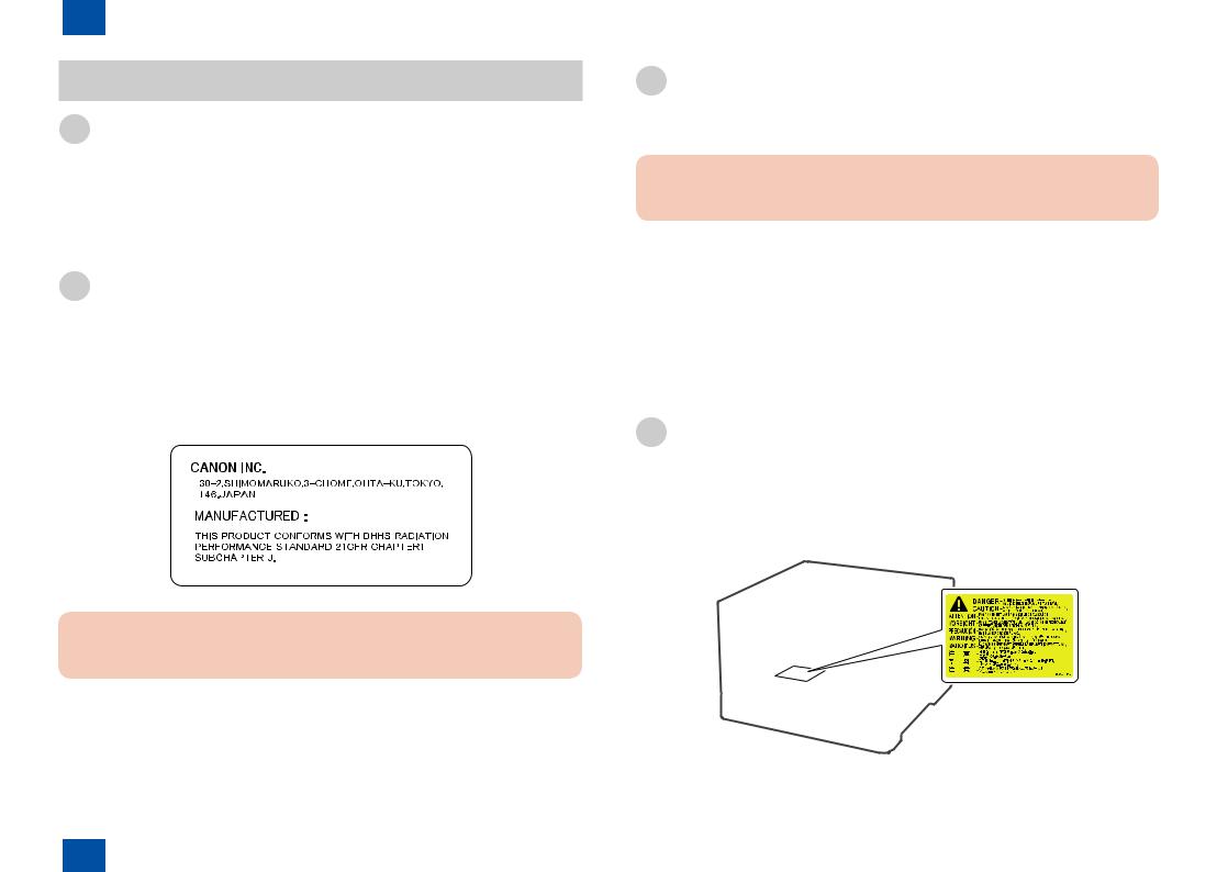
1 Product Description > Safety Precautions > How to Handle the Laser Scanner Unit
Safety Precautions
Laser Safety
Laser beam radiation sometimes causes a danger to human body. To prevent such a danger, the optical laser system used in this machine is hermetically closed by the protection housing and external cover so that a laser beam does not leak to outside. Therefore, a laser beam does not leak out of this machine as long as a user operates the machine in an ordinary manner.
CDRH Regulation
CDRH (Center for Devices and Radiological Health), which belongs to Food and Drug Administration in USA, put a regulation concerning laser products on August 2, 1976. This regulation is applied to laser products manufactured on and after August 1, 1976, and sales activities are prohibited in USA without receiving permission under the regulation.
The following figure shows the label indicating that permission has been received under the CDRH regulation, and it is obliged to attach it on all products sold in USA.
F-1-7
Caution :
A part of the description may be different depending on the type of product model.
1-18
Toner Safety
■
Caution :
Be sure not to throw toner into the fire. Doing so may cause an explosion.
■ How to Handle Adhered Toner
•When toner adhered to skin or clothes, completely remove it with dried tissue and wash with water.
•If hot water is used, toner cannot be removed because it becomes gel and penetrates into clothes permanently.
•Do not make toner come into contact with vinyl because it easily reacts with a vinyl material.
How to Handle the Laser Scanner Unit
An invisible laser beam is irradiated in the laser scanner unit.
If the laser beam enters an eye, it may cause damage to the eye. So, be sure not to disassemble the laser scanner unit. No adjustment can be made to the laser scanner unit in
this machine in the field. |
|
The label shown in the |
unit. |
F-1-8
1-18
1 Product Description > Safety Precautions > How to Handle the Laser Scanner Unit

1 Product Description > Safety Precautions > Points to Note when Performing Disassembly/Assembly
1-19
Points to Note when Replacing/Discarding a Lithium
Battery
Caution :
If the battery is replaced with an incorrect type of battery, it may cause an explosion.
Discard a used battery according to the instruction manual.
Points to Note when Performing Disassembly/Assembly
Be sure to follow the instruction shown below when performing disassembly/assembly.
1.Be sure to unplug the power plug for safety when performing disassembly/assembly.
2.If not otherwise specified, perform assembly in the procedure opposite to that of disassembly.
3.Perform assembly using correct types of screws, etc. (length/diameter) at correct positions.
4.A washer screw is used as a screw to fix a grounding wire and varistor, etc., to secure electrical conduction. Be sure to use this screw when performing assembly.
5.In principle, do not operate the machine in the condition where parts are removed.
6.Do not remove a paint-locked screw when performing disassembly.
1-19
1 Product Description > Safety Precautions > Points to Note when Performing Disassembly/Assembly

2 |
Technical Reference |
■Basic Configuration |
■Operation Sequence
■Laser Exposure System
■Image Formation System
■Fixing System
■Pickup Feeding System
■Controller System
■Embedded RDS
2 Technical Reference
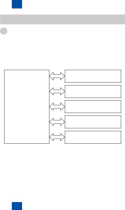
2 Technical Reference > Basic Configuration > Functional Configuration
2-2
Basic Configuration
Functional Configuration
The function of this machine is broadly classified into the following five blocks.
•Controller system
•Laser exposure system
•Image formation system
•Fixing system
•Pickup feeding system
The following figure shows the block category of the function.
|
Laser exposure system |
|
Image formation system |
Controller system |
Fixing system |
|
Pickup feeding system |
|
Controller system |
F-2-1
2-2
2 Technical Reference > Basic Configuration > Functional Configuration

2 Technical Reference > Operation Sequence > Overview
2-3
Operation Sequence
Overview
|
Interval |
|
Operation |
WAIT |
An interval from when the power |
Start up this machine so that printing can be |
|
(Wait) |
switch is turned on, the door |
performed. |
|
|
is closed, or sleep mode is |
• Heat up the fixing sleeve in the fixing |
|
|
cancelled to when the printer is |
|
assembly. |
|
ready to perform printing |
• Detect the presence of each cartridge and |
|
|
|
• |
unit. |
|
|
Move the ITB and developing assembly to |
|
|
|
• |
the home position. |
|
|
Perform ITB cleaning and secondary |
|
|
|
|
transfer outer roller cleaning |
STBY |
An interval from when WAIT or |
Maintain this machine so that printing can be |
|
(Standby) |
last rotation finishes to when |
performed. |
|
|
the print instruction command is |
• Make the machine move to the sleep status |
|
|
entered or the power switch is |
|
by the sleep instruction command. |
|
turned off |
• Start control by the calibration execution |
|
|
|
|
command. |
|
|
|
|
INTR |
An interval from when the print |
Make preparation to perform printing. |
|
(Initial rotation) |
instruction command is entered |
• Operate the high-voltage power supply. |
|
|
to when pickup is performed |
• Operate the laser scanner unit. |
|
|
|
• |
Start up the fixing assembly. |
PRNT |
An interval from when initial |
Execute printing. |
|
(Print) |
rotation finishes to when fixing of |
• Form an image on the photosensitive drum. |
|
|
the last paper finishes |
• Transfer toner into paper. |
|
|
|
• |
Fix toner on paper. |
LSTR |
An interval from when printing |
Deliver the last paper. |
|
(Last rotation) |
finishes to when each motor |
• Stop the high-voltage power supply. |
|
|
stops |
• Stop the laser scanner unit. |
|
|
|
When the print command is entered, the |
|
|
|
machine moves to the initial rotation state |
|
|
|
after last rotation finishes. |
|
|
|
|
T-2-1 |
2-3
2 Technical Reference > Operation Sequence > Overview

2 Technical Reference > Laser Exposure System > Safety
Laser Exposure System
Overview
The laser exposure system forms a latent image on the photosensitive drum according to the video signal sent from the main controller.
The laser scanner unit consists of the laser unit and the scanner motor unit. Each unit is controlled by the signal entered from the DC controller.
Two laser scanner units are used in this machine. One is a unit for Y/M, and the other is for C/Bk, which are common units.
Photosensitive drum (M)
Photosensitive drum (Y)
Laser unit
BD sensor
Yellow laser
Magenta laser
signalVideo |
controlLasersignal |
signalinputBD |
motorScanner controlspeed signal |
|
|
|
Scanner mirror |
|
|
|
Scanner motor unit |
|
|
|
DC controller |
Main controller
F-2-2
2-4
One laser scanner unit consists of the laser drive unit, which controls the laser unit, and the scanner motor unit, which controls the scanner motor. One scanner motor and scanner mirror reflect laser beams for two colors.
These parts are contained in the laser scanner unit and controlled by the DC controller. The DC controller irradiates each laser beam according to the video signal received from the main controller. The laser beam falls on the scanner mirror rotating at constant speed. The laser beam reflected from the scanner mirror is irradiated on the photosensitive drum.
Detecting a Failure in the Optical Assembly
When the laser scanner is placed in the following condition, the DC controller judges that a failure occurred in the laser scanner unit and reports it to the main controller.
•Laser failure
When the laser is turned on for a specified time at startup of the laser scanner unit, either of the two laser beams does not reach the specified laser intensity.
•Scanner motor startup failure
Even when a specified time elapses after startup of the laser scanner unit, the number of rotations of the scanner motor does not reach a specified number of times.
•Scanner motor rotation failure
When a specified BD interval cannot be detected during printing, it is judged that a BD error occurred. When the BD interval cannot recover from the fault even after a specified time elapsed after it was judged that a BD error occurred, it is considered that a scanner motor rotation failure occurred.
Safety
The laser scanner unit of this machine does not have a mechanical laser shutter.
To secure safety, two interlock switches for +5VC are mounted. When the front door or right door is opened, the interlock switch works and blocks power distribution to the laser scanner unit.
2-4
2 Technical Reference > Laser Exposure System > Safety

2 Technical Reference > Image Formation System > Image Formation Process > Overview
Image Formation System
Overview
The image formation system forms a toner image on paper.
The system consists of the following components.
•Four cartridges
•ITB unit
•Fixing assembly
•Laser scanner unit
The DC controller controls the laser scanner unit and high-voltage power supply PCB(upper/ lower), forms a toner image on the photosensitive drum based on a video signal, and transfers/fixes the image on paper via the ITB unit.
|
Photosensitive drum |
Fixing |
|
|
Cartridge |
assembly |
Laser beam
ITB unit
Laser scanner unit
|
Upper high-voltage |
|
Laser scanner unit |
power supply PCD |
|
|
||
Lower high-voltage |
DC controller |
|
power supply PCD |
||
|
||
|
F-2-3 |
2-5
Image Formation Process
■ Overview
The image formation process of this machine is broadly classified into six blocks and ten steps.
1.Static latent image formation block
Step 1: Pre-exposure Step 2: Primary charging
Step 3: Laser beam exposure
2.Development block Step 4: Development
3.Transfer block
Step 5: Primary transfer Step 6: Secondary transfer Step 7: Separation
4.Fixing block
Step 8: Fixing
5.ITB cleaning block
Step 9: ITB cleaning
6.Photosensitive drum cleaning block
Step 10: Photosensitive drum cleaning
: Block |
: Flow of paper |
Delivery |
|
|
|
|
|
|
|
: Step |
: Drum rotation direction |
|
|
8. Fixing |
|
|
Fixing |
|
|
ITB cleaning |
|
Transfer |
|
|
|
|
|
7. Separation |
|
9. ITB cleaning |
|
|
|
|
|
|
|
|
|
|
|
|
6. Secondary transfer |
|
|
5. Primary transfer |
|
|
|
|
10. Drum cleaning |
Drum cleaning |
||
|
|
|
||
|
4. Development |
|
|
|
|
Development |
1. Pre-exposure |
|
|
|
2. Primary charging |
|
Registration |
|
|
3. Laser beam exposure |
|
|
|
|
Static latent image formation |
|
|
|
|
|
Paper feed |
F-2-4 |
|
|
|
|
|
|
2-5
2 Technical Reference > Image Formation System > Image Formation Process > Overview
Loading...