


 Loading...
Service Manual
MF5700 Series
May 31 2005
Application
This manual has been issued by Canon Inc. for qualified persons to learn technical theory, installation, maintenance, and repair of products. This manual covers all localities where the products are sold. For this reason, there may be information in this manual that does not apply to your locality.
Corrections
This manual may contain technical inaccuracies or typographical errors due to improvements or changes in products. When changes occur in applicable products or in the contents of this manual, Canon will release technical information as the need arises. In the event of major changes in the contents of this manual over a long or short period, Canon will issue a new edition of this manual.
The following paragraph does not apply to any countries where such provisions are inconsistent with local law.
Trademarks
The product names and company names used in this manual are the registered trademarks of the individual companies.
Copyright
This manual is copyrighted with all rights reserved. Under the copyright laws, this manual may not be copied, reproduced or translated into another language, in whole or in part, without the written consent of Canon Inc.
COPYRIGHT © 2001 CANON INC.
Printed in Japan
Caution
Use of this manual should be strictly supervised to avoid disclosure of confidential information.
Introduction
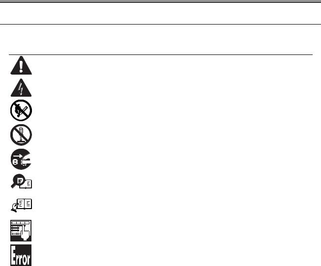
Symbols Used
This documentation uses the following symbols to indicate special information:
Symbol Description
Indicates an item of a non-specific nature, possibly classified as Note, Caution, or Warning.
Indicates an item requiring care to avoid electric shocks.
Indicates an item requiring care to avoid combustion (fire).
Indicates an item prohibiting disassembly to avoid electric shocks or problems.
Indicates an item requiring disconnection of the power plug from the electric outlet.
Indicates an item intended to provide notes assisting the understanding of the topic in question.
Memo
Indicates an item of reference assisting the understanding of the topic in question.
REF.
Provides a description of a service mode.
Provides a description of the nature of an error indication.

Introduction
The following rules apply throughout this Service Manual:
1.Each chapter contains sections explaining the purpose of specific functions and the relationship between electrical and mechanical systems with reference to the timing of operation.
In the diagrams,  represents the path of mechanical drive; where a signal name accompanies the symbol , the arrow
  indicates the
direction of the electric signal.
The expression "turn on the power" means flipping on the power switch, closing the front door, and closing the delivery unit door, which results in supplying the machine with power.
2.In the digital circuits, '1'is used to indicate that the voltage level of a given signal is "High", while '0' is used to indicate "Low".(The voltage value, however, differs from circuit to circuit.) In addition, the asterisk (*) as in "DRMD*" indicates that the DRMD signal goes on when '0'.
In practically all cases, the internal mechanisms of a microprocessor cannot be checked in the field. Therefore, the operations of the microprocessors used in the machines are not discussed: they are explained in terms of from sensors to the input of the DC controller PCB and from the output of the DC controller PCB to the loads.
The descriptions in this Service Manual are subject to change without notice for product improvement or other purposes, and major changes will be communicated in the form of Service Information bulletins.
All service persons are expected to have a good understanding of the contents of this Service Manual and all relevant Service Information bulletins and be able to identify and isolate faults in the machine."

Contents
Contents
Chapter 1 PRODUCT DESCRIPTION |
|
1.1 Product Specifications ................................................................................................................................ |
1- 1 |
1.1.1 Product Specifications ............................................................................................................................................. |
1- 1 |
1.1.2 Product Specifications ............................................................................................................................................. |
1- 2 |
1.2 Detailed Specifications ............................................................................................................................... |
1- 6 |
1.2.1 Printing Speed ......................................................................................................................................................... |
1- 6 |
1.2.2 Stack Upon Delivery ................................................................................................................................................ |
1- 6 |
1.2.3 Scanning Range (Transmission) ............................................................................................................................. |
1- 6 |
1.2.4 Printing Range (Reception) ..................................................................................................................................... |
1- 7 |
1.2.5 Printing Range (Printer)........................................................................................................................................... |
1- 8 |
1.2.6 System Requirements for Printer Driver.................................................................................................................. |
1- 9 |
1.3 Names of Parts......................................................................................................................................... |
1- 11 |
1.3.1 External View......................................................................................................................................................... |
1- 11 |
1.3.2 Operation panel ..................................................................................................................................................... |
1- 13 |
1.3.3 Operation panel ..................................................................................................................................................... |
1- 13 |
1.4 Safety ....................................................................................................................................................... |
1- 15 |
1.4.1 Safety of Laser Light.............................................................................................................................................. |
1- 15 |
1.4.2 Handling the Laser Unit ......................................................................................................................................... |
1- 15 |
1.4.3 Safety of Toner ...................................................................................................................................................... |
1- 15 |
1.4.4 Point to Note about Fire......................................................................................................................................... |
1- 15 |
1.4.5 Point to Note about Battery Replacement ............................................................................................................. |
1- 15 |
Chapter 2 TECHNICAL REFERENCE |
|
2.1 Document Feed and Exposure System...................................................................................................... |
2- 1 |
2.1.1 Overview/Configuration ........................................................................................................................................... |
2- 1 |
2.1.1.1 Overview .................................................................................................................................................................................. |
2- 1 |
2.2 Laser Exposure .......................................................................................................................................... |
2- 3 |
2.2.1 Overview/Configuration ........................................................................................................................................... |
2- 3 |
2.2.1.1 Overview .................................................................................................................................................................................. |
2- 3 |
2.3 Image Formation ........................................................................................................................................ |
2- 5 |
2.3.1 Overview/Configuration ........................................................................................................................................... |
2- 5 |
2.3.1.1 Overview .................................................................................................................................................................................. |
2- 5 |
2.4 Pickup and Feed System............................................................................................................................ |
2- 6 |
2.4.1 Overview/Configuration ........................................................................................................................................... |
2- 6 |
2.4.1.1 Overview .................................................................................................................................................................................. |
2- 6 |
2.4.2 Detection Jams........................................................................................................................................................ |
2- 7 |
2.4.2.1 Jam Detection Outline.............................................................................................................................................................. |
2- 7 |
2.4.2.2 Delay Jams .............................................................................................................................................................................. |
2- 7 |
2.4.2.3 Stationary Jams ....................................................................................................................................................................... |
2- 7 |
2.4.2.4 Other Jams .............................................................................................................................................................................. |
2- 7 |
2.5 Fixing Unit................................................................................................................................................... |
2- 9 |
2.5.1 Overview/Configuration ........................................................................................................................................... |
2- 9 |
2.5.1.1 Overview .................................................................................................................................................................................. |
2- 9 |
2.5.2 Protective Function.................................................................................................................................................. |
2- 9 |
2.5.2.1 Protective Mechanisms............................................................................................................................................................ |
2- 9 |
2.5.2.2 Detecting a Fault in the Fixing Assembly............................................................................................................................... |
2- 10 |
2.6 External and Controls ............................................................................................................................... |
2- 11 |
2.6.1 Power Supply ........................................................................................................................................................ |
2- 11 |
2.6.1.1 |
Backup Battery....................................................................................................................................................................... |
2- 11 |
2.6.1.2 |
Energy-Saving Function......................................................................................................................................................... |
2- 11 |

Contents
Chapter 3 DISASSEMBLY AND ASSEMBLY |
|
3.1 EXTERNAL AND CONTROLS SYSTEM |
................................................................................................... 3- 1 |
3.1.1 Front Cover .............................................................................................................................................................. |
3- 1 |
3.1.1.1 Removing the Cassette............................................................................................................................................................ |
3- 1 |
3.1.1.2 Removing the Reader Right Front Cover ................................................................................................................................ |
3- 1 |
3.1.1.3 Removing the Right Cover....................................................................................................................................................... |
3- 1 |
3.1.1.4 Removing the Reader Left Front Cover ................................................................................................................................... |
3- 1 |
3.1.1.5 Removing the Left Cover ......................................................................................................................................................... |
3- 1 |
3.1.1.6 Removing the Front Cover....................................................................................................................................................... |
3- 2 |
3.1.2 Rear Cover............................................................................................................................................................... |
3- 2 |
3.1.2.1 Removing the Cassette............................................................................................................................................................ |
3- 2 |
3.1.2.2 Removing the Reader Right Front Cover ................................................................................................................................ |
3- 2 |
3.1.2.3 Removing the Right Cover....................................................................................................................................................... |
3- 2 |
3.1.2.4 Removing the Reader Left Front Cover ................................................................................................................................... |
3- 2 |
3.1.2.5 Removing the Left Cover ......................................................................................................................................................... |
3- 3 |
3.1.2.6 Removing the Rear Cover ....................................................................................................................................................... |
3- 3 |
3.1.3 Top Cover ................................................................................................................................................................ |
3- 3 |
3.1.3.1 Removing the Cassette............................................................................................................................................................ |
3- 3 |
3.1.3.2 Removing the Reader Right Front Cover ................................................................................................................................ |
3- 3 |
3.1.3.3 Removing the Right Cover....................................................................................................................................................... |
3- 3 |
3.1.3.4 Removing the Reader Left Front Cover ................................................................................................................................... |
3- 4 |
3.1.3.5 Removing the Left Cover ......................................................................................................................................................... |
3- 4 |
3.1.3.6 Removing the Front Cover....................................................................................................................................................... |
3- 4 |
3.1.3.7 Removing the Rear Cover ....................................................................................................................................................... |
3- 4 |
3.1.3.8 Removing the NCU Board ....................................................................................................................................................... |
3- 5 |
3.1.3.9 Removing the NCU Case......................................................................................................................................................... |
3- 5 |
3.1.3.10 Removing the Scanner Unit ................................................................................................................................................... |
3- 5 |
3.1.3.11 Removing the Top Cover ....................................................................................................................................................... |
3- 6 |
3.1.4 Right Cover .............................................................................................................................................................. |
3- 6 |
3.1.4.1 Removing the Cassette............................................................................................................................................................ |
3- 6 |
3.1.4.2 Removing the Reader Right Front Cover................................................................................................................................. |
3- 6 |
3.1.4.3 Removing the Right Cover....................................................................................................................................................... |
3- 6 |
3.1.5 Left Cover ................................................................................................................................................................ |
3- 6 |
3.1.5.1 Removing the Cassette............................................................................................................................................................ |
3- 6 |
3.1.5.2 Removing the Reader Left Front Cover ................................................................................................................................... |
3- 6 |
3.1.5.3 Removing the Left Cover ......................................................................................................................................................... |
3- 7 |
3.1.6 Right Front Cover..................................................................................................................................................... |
3- 7 |
3.1.6.1 Removing the Cassette............................................................................................................................................................ |
3- 7 |
3.1.6.2 Removing the Reader Right Front Cover ................................................................................................................................ |
3- 7 |
3.1.6.3 Removing the Right Cover....................................................................................................................................................... |
3- 7 |
3.1.6.4 Removing the Reader Left Front Cover ................................................................................................................................... |
3- 7 |
3.1.6.5 Removing the Left Cover ......................................................................................................................................................... |
3- 8 |
3.1.6.6 Removing the Front Cover....................................................................................................................................................... |
3- 8 |
3.1.6.7 Removing the Right Front Cover ............................................................................................................................................. |
3- 8 |
3.1.7 Left Front Cover....................................................................................................................................................... |
3- 8 |
3.1.7.1 Removing the Cassette............................................................................................................................................................ |
3- 8 |
3.1.7.2 Removing the Reader Right Front Cover ................................................................................................................................ |
3- 8 |
3.1.7.3 Removing the Right Cover....................................................................................................................................................... |
3- 8 |
3.1.7.4 Removing the Reader Left Front Cover ................................................................................................................................... |
3- 9 |
3.1.7.5 Removing the Left Cover ......................................................................................................................................................... |
3- 9 |
3.1.7.6 Removing the Front Cover....................................................................................................................................................... |
3- 9 |
3.1.7.7 Removing the Left Front Cover................................................................................................................................................ |
3- 9 |
3.1.8 Operation Panel Cover .......................................................................................................................................... |
3- 10 |
3.1.8.1 Removing the LCD Cover ...................................................................................................................................................... |
3- 10 |
3.1.8.2 Removing the Operation panel Cover.................................................................................................................................... |
3- 10 |
3.1.9 Operation Panel Unit.............................................................................................................................................. |
3- 10 |
3.1.9.1 Removing the LCD Cover ...................................................................................................................................................... |
3- 10 |
3.1.9.2 Removing the Reader Left Front Cover ................................................................................................................................. |
3- 10 |
3.1.9.3 Removing the Operation Panel Unit ...................................................................................................................................... |
3- 10 |
3.1.10 SCNT Board......................................................................................................................................................... |
3- 10 |

Contents
3.1.10.1 Removing the Cassette........................................................................................................................................................ |
3- 10 |
3.1.10.2 Removing the Reader Right Front Cover ............................................................................................................................ |
3- 11 |
3.1.10.3 Removing the Right Cover ................................................................................................................................................... |
3- 11 |
3.1.10.4 Removing the Reader Left Front Cover ............................................................................................................................... |
3- 11 |
3.1.10.5 Removing the Left Cover ..................................................................................................................................................... |
3- 11 |
3.1.10.6 Removing the NCU Board.................................................................................................................................................... |
3- 11 |
3.1.10.7 Removing the NCU Case..................................................................................................................................................... |
3- 12 |
3.1.10.8 Removing the Scanner Unit ................................................................................................................................................. |
3- 12 |
3.1.10.9 Removing the Board Unit ..................................................................................................................................................... |
3- 12 |
3.1.10.10 Removing the SCNT Board (for Units with the Fax Function)............................................................................................ |
3- 13 |
3.1.10.11 Removing the SCNT Board (for Units without the Fax Function)....................................................................................... |
3- 13 |
3.1.11 DCNT Board ........................................................................................................................................................ |
3- 13 |
3.1.11.1 Removing the Cassette........................................................................................................................................................ |
3- 13 |
3.1.11.2 Removing the Reader Right Front Cover ............................................................................................................................ |
3- 13 |
3.1.11.3 Removing the Right Cover ................................................................................................................................................... |
3- 13 |
3.1.11.4 Removing the Reader Left Front Cover ............................................................................................................................... |
3- 14 |
3.1.11.5 Removing the Left Cover ..................................................................................................................................................... |
3- 14 |
3.1.11.6 Removing the NCU Board.................................................................................................................................................... |
3- 14 |
3.1.11.7 Removing the NCU Case..................................................................................................................................................... |
3- 14 |
3.1.11.8 Removing the Front Cover ................................................................................................................................................... |
3- 15 |
3.1.11.9 Removing the Left Front Cover ............................................................................................................................................ |
3- 15 |
3.1.11.10 Removing the DCNT Board................................................................................................................................................ |
3- 15 |
3.1.12 NCU Board .......................................................................................................................................................... |
3- 15 |
3.1.12.1 Removing the Cassette........................................................................................................................................................ |
3- 15 |
3.1.12.2 Removing the Reader Left Front Cover ............................................................................................................................... |
3- 15 |
3.1.12.3 Removing the Left Cover ..................................................................................................................................................... |
3- 15 |
3.1.12.4 Removing the NCU Board.................................................................................................................................................... |
3- 16 |
3.1.13 Modular Board ..................................................................................................................................................... |
3- 16 |
3.1.13.1 Removing the Cassette........................................................................................................................................................ |
3- 16 |
3.1.13.2 Removing the Reader Left Front Cover ............................................................................................................................... |
3- 16 |
3.1.13.3 Removing the Left Cover ..................................................................................................................................................... |
3- 16 |
3.1.13.4 Removing the Modular Board .............................................................................................................................................. |
3- 16 |
3.1.14 Power Supply PCB .............................................................................................................................................. |
3- 17 |
3.1.14.1 Removing the Cassette........................................................................................................................................................ |
3- 17 |
3.1.14.2 Removing the Reader Right Front Cover ............................................................................................................................ |
3- 17 |
3.1.14.3 Removing the Right Cover ................................................................................................................................................... |
3- 17 |
3.1.14.4 Removing the Reader Left Front Cover ............................................................................................................................... |
3- 17 |
3.1.14.5 Removing the Left Cover ..................................................................................................................................................... |
3- 17 |
3.1.14.6 Removing the NCU Board and Modular Board .................................................................................................................... |
3- 18 |
3.1.14.7 Removing the NCU Case..................................................................................................................................................... |
3- 18 |
3.1.14.8 Removing the Rear Cover.................................................................................................................................................... |
3- 18 |
3.1.14.9 Removing the Power Supply Shield Plate............................................................................................................................ |
3- 18 |
3.1.14.10 Removing the Power Supply Assembly ............................................................................................................................. |
3- 18 |
3.1.14.11 Removing the Power Supply Board ................................................................................................................................... |
3- 19 |
3.1.15 High-voitage Power Supply PCB ......................................................................................................................... |
3- 19 |
3.1.15.1 Removing the Cassette........................................................................................................................................................ |
3- 19 |
3.1.15.2 Removing the Reader Right Front Cover ............................................................................................................................ |
3- 19 |
3.1.15.3 Removing the Right Cover ................................................................................................................................................... |
3- 19 |
3.1.15.4 Removing the Reader Left Front Cover ............................................................................................................................... |
3- 20 |
3.1.15.5 Removing the Left Cover ..................................................................................................................................................... |
3- 20 |
3.1.15.6 Removing the NCU Board and Modular Board .................................................................................................................... |
3- 20 |
3.1.15.7 Removing the NCU Case..................................................................................................................................................... |
3- 20 |
3.1.15.8 Removing the Rear Cover.................................................................................................................................................... |
3- 21 |
3.1.15.9 Removing the Power Supply Shield plate ............................................................................................................................ |
3- 21 |
3.1.15.10 Removing the Power Supply Assembly ............................................................................................................................. |
3- 21 |
3.1.15.11 Removing the High-Voltage Power Supply Board.............................................................................................................. |
3- 21 |
3.1.16 Top Sensor .......................................................................................................................................................... |
3- 22 |
3.1.16.1 Removing the Cassette........................................................................................................................................................ |
3- 22 |
3.1.16.2 Removing the Reader Right Front Cover ............................................................................................................................ |
3- 22 |
3.1.16.3 Removing the Right Cover ................................................................................................................................................... |
3- 22 |
3.1.16.4 Removing the Reader Left Front Cover ............................................................................................................................... |
3- 22 |

Contents
3.1.16.5 Removing the Left Cover ..................................................................................................................................................... |
3- 22 |
3.1.16.6 Removing the Front Cover ................................................................................................................................................... |
3- 23 |
3.1.16.7 Removing the Rear Cover.................................................................................................................................................... |
3- 23 |
3.1.16.8 Removing the NCU Board and Modular Board .................................................................................................................... |
3- 23 |
3.1.16.9 Removing the NCU Case..................................................................................................................................................... |
3- 23 |
3.1.16.10 Removing the Scanner Unit ............................................................................................................................................... |
3- 24 |
3.1.16.11 Removing the Plate ............................................................................................................................................................ |
3- 24 |
3.1.16.12 Removing the Power Supply Shield Plate.......................................................................................................................... |
3- 24 |
3.1.16.13 Removing the Power Supply Assembly ............................................................................................................................. |
3- 24 |
3.1.16.14 Removing the Top Sensor.................................................................................................................................................. |
3- 25 |
3.1.17 Paper Delivery Sensor ......................................................................................................................................... |
3- 25 |
3.1.17.1 Removing the Cassette........................................................................................................................................................ |
3- 25 |
3.1.17.2 Removing the Reader Right Front Cover ............................................................................................................................ |
3- 25 |
3.1.17.3 Removing the Right Cover ................................................................................................................................................... |
3- 25 |
3.1.17.4 Removing the Reader Left Front Cover ............................................................................................................................... |
3- 25 |
3.1.17.5 Removing the Left Cover ..................................................................................................................................................... |
3- 25 |
3.1.17.6 Removing the Front Cover ................................................................................................................................................... |
3- 26 |
3.1.17.7 Removing the Rear Cover.................................................................................................................................................... |
3- 26 |
3.1.17.8 Removing the NCU Board and Modular Board .................................................................................................................... |
3- 26 |
3.1.17.9 Removing the NCU Case..................................................................................................................................................... |
3- 26 |
3.1.17.10 Removing the Scanner Unit ............................................................................................................................................... |
3- 27 |
3.1.17.11 Removing the Plate ............................................................................................................................................................ |
3- 27 |
3.1.17.12 Removing the Power Supply Shield Plate.......................................................................................................................... |
3- 27 |
3.1.17.13 Removing the Paper Delivery Sensor ................................................................................................................................ |
3- 27 |
3.1.18 Paper Full Sensor ................................................................................................................................................ |
3- 28 |
3.1.18.1 Removing the Cassette........................................................................................................................................................ |
3- 28 |
3.1.18.2 Removing the Reader Right Front Cover ............................................................................................................................ |
3- 28 |
3.1.18.3 Removing the Right Cover ................................................................................................................................................... |
3- 28 |
3.1.18.4 Removing the Reader Left Front Cover ............................................................................................................................... |
3- 28 |
3.1.18.5 Removing the Left Cover ..................................................................................................................................................... |
3- 28 |
3.1.18.6 Removing the Front Cover ................................................................................................................................................... |
3- 29 |
3.1.18.7 Removing the Rear Cover.................................................................................................................................................... |
3- 29 |
3.1.18.8 Removing the NCU Board.................................................................................................................................................... |
3- 29 |
3.1.18.9 Removing the NCU Case..................................................................................................................................................... |
3- 29 |
3.1.18.10 Removing the Scanner Unit ............................................................................................................................................... |
3- 30 |
3.1.18.11 Removing the Top Cover ................................................................................................................................................... |
3- 30 |
3.1.18.12 Removing the Paper Full Sensor ....................................................................................................................................... |
3- 30 |
3.1.19 Toner Sensor ....................................................................................................................................................... |
3- 30 |
3.1.19.1 Removing the Cassette........................................................................................................................................................ |
3- 30 |
3.1.19.2 Removing the Reader Right Front Cover............................................................................................................................. |
3- 30 |
3.1.19.3 Removing the Right Cover ................................................................................................................................................... |
3- 31 |
3.1.19.4 Removing the Reader Left Front Cover ............................................................................................................................... |
3- 31 |
3.1.19.5 Removing the Left Cover ..................................................................................................................................................... |
3- 31 |
3.1.19.6 Removing the Front Cover ................................................................................................................................................... |
3- 31 |
3.1.19.7 Removing the Left Front Cover ............................................................................................................................................ |
3- 32 |
3.1.19.8 Removing the Toner Sensor ................................................................................................................................................ |
3- 32 |
3.1.20 Speaker................................................................................................................................................................ |
3- 32 |
3.1.20.1 Removing the Cassette........................................................................................................................................................ |
3- 32 |
3.1.20.2 Removing the Reader Right Front Cover............................................................................................................................. |
3- 32 |
3.1.20.3 Removing the Right Cover ................................................................................................................................................... |
3- 32 |
3.1.20.4 Removing the Reader Left Front Cover ............................................................................................................................... |
3- 32 |
3.1.20.5 Removing the Left Cover ..................................................................................................................................................... |
3- 33 |
3.1.20.6 Removing the NCU Board.................................................................................................................................................... |
3- 33 |
3.1.20.7 Removing the NCU Case..................................................................................................................................................... |
3- 33 |
3.1.20.8 Removing the Scanner Unit ................................................................................................................................................. |
3- 33 |
3.1.20.9 Removing the Board Unit ..................................................................................................................................................... |
3- 34 |
3.1.20.10 Removing the ADF Unit...................................................................................................................................................... |
3- 34 |
3.1.20.11 Removing the LCD Cover .................................................................................................................................................. |
3- 34 |
3.1.20.12 Removing the Operation Panel Unit................................................................................................................................... |
3- 35 |
3.1.20.13 Removing the Scanner Cover Unit..................................................................................................................................... |
3- 35 |
3.1.20.14 Removing the Speaker....................................................................................................................................................... |
3- 35 |
|
Contents |
|
|
|
|
3.2 Document Feed/Exposure System........................................................................................................... |
3- 36 |
3.2.1 Scanner Unit.......................................................................................................................................................... |
3- 36 |
3.2.1.1 Removing the Cassette ......................................................................................................................................................... |
3- 36 |
3.2.1.2 Removing the Reader Right Front Cover............................................................................................................................... |
3- 36 |
3.2.1.3 Removing the Right Cover..................................................................................................................................................... |
3- 36 |
3.2.1.4 Removing the Reader Left Front Cover ................................................................................................................................. |
3- 36 |
3.2.1.5 Removing the Left Cover ....................................................................................................................................................... |
3- 36 |
3.2.1.6 Removing the NCU Board ..................................................................................................................................................... |
3- 37 |
3.2.1.7 Removing the NCU Case....................................................................................................................................................... |
3- 37 |
3.2.1.8 Removing the Scanner Unit ................................................................................................................................................... |
3- 37 |
3.2.2 ADF Unit ................................................................................................................................................................ |
3- 37 |
3.2.2.1 Removing the Cassette.......................................................................................................................................................... |
3- 37 |
3.2.2.2 Removing the Reader Right Front Cover............................................................................................................................... |
3- 38 |
3.2.2.3 Removing the Right Cover..................................................................................................................................................... |
3- 38 |
3.2.2.4 Removing the Reader Left Front Cover ................................................................................................................................. |
3- 38 |
3.2.2.5 Removing the Left Cover ....................................................................................................................................................... |
3- 38 |
3.2.2.6 Removing the NCU Board ..................................................................................................................................................... |
3- 38 |
3.2.2.7 Removing the NCU Case....................................................................................................................................................... |
3- 39 |
3.2.2.8 Removing the Scanner Unit ................................................................................................................................................... |
3- 39 |
3.2.2.9 Removing the Board Unit....................................................................................................................................................... |
3- 39 |
3.2.2.10 Removing the ADF Unit ....................................................................................................................................................... |
3- 40 |
3.2.3 Scanner Cover Unit ............................................................................................................................................... |
3- 40 |
3.2.3.1 Removing the Cassette.......................................................................................................................................................... |
3- 40 |
3.2.3.2 Removing the Reader Right Front Cover .............................................................................................................................. |
3- 40 |
3.2.3.3 Removing the Right Cover..................................................................................................................................................... |
3- 40 |
3.2.3.4 Removing the Reader Left Front Cover ................................................................................................................................. |
3- 40 |
3.2.3.5 Removing the Left Cover ....................................................................................................................................................... |
3- 41 |
3.2.3.6 Removing the NCU Board ..................................................................................................................................................... |
3- 41 |
3.2.3.7 Removing the NCU Case....................................................................................................................................................... |
3- 41 |
3.2.3.8 Removing the Scanner Unit ................................................................................................................................................... |
3- 41 |
3.2.3.9 Removing the Board Unit....................................................................................................................................................... |
3- 42 |
3.2.3.10 Removing the ADF Unit ....................................................................................................................................................... |
3- 42 |
3.2.3.11 Removing the LCD Cover .................................................................................................................................................... |
3- 42 |
3.2.3.12 Removing the Operation Panel Unit..................................................................................................................................... |
3- 43 |
3.2.3.13 Removing the Scanner Cover Unit....................................................................................................................................... |
3- 43 |
3.2.4 CCD Unit ............................................................................................................................................................... |
3- 43 |
3.2.4.1 Removing the Cassette.......................................................................................................................................................... |
3- 43 |
3.2.4.2 Removing the Reader Right Front Cover .............................................................................................................................. |
3- 43 |
3.2.4.3 Removing the Right Cover..................................................................................................................................................... |
3- 43 |
3.2.4.4 Removing the Reader Left Front Cover ................................................................................................................................. |
3- 43 |
3.2.4.5 Removing the Left Cover ....................................................................................................................................................... |
3- 44 |
3.2.4.6 Removing the NCU Board ..................................................................................................................................................... |
3- 44 |
3.2.4.7 Removing the NCU Case....................................................................................................................................................... |
3- 44 |
3.2.4.8 Removing the Scanner Unit ................................................................................................................................................... |
3- 44 |
3.2.4.9 Removing the Board Unit....................................................................................................................................................... |
3- 45 |
3.2.4.10 Removing the ADF Unit ....................................................................................................................................................... |
3- 45 |
3.2.4.11 Removing the LCD Cover .................................................................................................................................................... |
3- 45 |
3.2.4.12 Removing the Operation Panel Unit..................................................................................................................................... |
3- 46 |
3.2.4.13 Removing the Scanner Cover Unit....................................................................................................................................... |
3- 46 |
3.2.4.14 Removing the Flatbed Motor Unit ........................................................................................................................................ |
3- 46 |
3.2.4.15 Removing the CCD Unit....................................................................................................................................................... |
3- 46 |
3.2.5 Flatbed Motor Unit ................................................................................................................................................. |
3- 46 |
3.2.5.1 Removing the Cassette.......................................................................................................................................................... |
3- 46 |
3.2.5.2 Removing the Reader Right Front Cover .............................................................................................................................. |
3- 46 |
3.2.5.3 Removing the Right Cover..................................................................................................................................................... |
3- 47 |
3.2.5.4 Removing the Reader Left Front Cover ................................................................................................................................. |
3- 47 |
3.2.5.5 Removing the Left Cover ....................................................................................................................................................... |
3- 47 |
3.2.5.6 Removing the NCU Board ..................................................................................................................................................... |
3- 47 |
3.2.5.7 Removing the NCU Case....................................................................................................................................................... |
3- 48 |
3.2.5.8 Removing the Scanner Unit ................................................................................................................................................... |
3- 48 |
3.2.5.9 Removing the Board Unit....................................................................................................................................................... |
3- 48 |

Contents
3.2.5.10 Removing the ADF Unit ....................................................................................................................................................... |
3- 49 |
3.2.5.11 Removing the LCD Cover .................................................................................................................................................... |
3- 49 |
3.2.5.12 Removing the Operation Panel Unit..................................................................................................................................... |
3- 49 |
3.2.5.13 Removing the Scanner Cover Unit....................................................................................................................................... |
3- 49 |
3.2.5.14 Removing the Flatbed Motor Unit ........................................................................................................................................ |
3- 49 |
3.3 LASER EXPOSURE SYSTEM................................................................................................................. |
3- 51 |
3.3.1 Laser/Scanner Unit ................................................................................................................................................ |
3- 51 |
3.3.1.1 Removing the Cassette.......................................................................................................................................................... |
3- 51 |
3.3.1.2 Removing the Reader Right Front Cover .............................................................................................................................. |
3- 51 |
3.3.1.3 Removing the Right Cover..................................................................................................................................................... |
3- 51 |
3.3.1.4 Removing the Reader Left Front Cover ................................................................................................................................. |
3- 51 |
3.3.1.5 Removing the Left Cover ....................................................................................................................................................... |
3- 51 |
3.3.1.6 Removing the Front Cover..................................................................................................................................................... |
3- 52 |
3.3.1.7 Removing the Rear Cover ..................................................................................................................................................... |
3- 52 |
3.3.1.8 Removing the NCU Board ..................................................................................................................................................... |
3- 52 |
3.3.1.9 Removing the NCU Case....................................................................................................................................................... |
3- 52 |
3.3.1.10 Removing the Scanner Unit ................................................................................................................................................. |
3- 53 |
3.3.1.11 Removing the Top Cover and Left Front Cover ................................................................................................................... |
3- 53 |
3.3.1.12 Removing the Laser/Scanner Unit ....................................................................................................................................... |
3- 53 |
3.4 IMAGE FORMATION SYSTEM................................................................................................................ |
3- 54 |
3.4.1 Transfer Charging Roller........................................................................................................................................ |
3- 54 |
3.4.1.1 Removing the Transfer Charging Roller ................................................................................................................................ |
3- 54 |
3.5 PICKUP AND FEEDING SYSTEM........................................................................................................... |
3- 55 |
3.5.1 Cassette Pickup Roller........................................................................................................................................... |
3- 55 |
3.5.1.1 Removing the Cassette.......................................................................................................................................................... |
3- 55 |
3.5.1.2 Removing the Reader Right Front Cover .............................................................................................................................. |
3- 55 |
3.5.1.3 Removing the Right Cover..................................................................................................................................................... |
3- 55 |
3.5.1.4 Removing the Reader Left Front Cover ................................................................................................................................. |
3- 55 |
3.5.1.5 Removing the Left Cover ....................................................................................................................................................... |
3- 55 |
3.5.1.6 Removing the Front Cover..................................................................................................................................................... |
3- 56 |
3.5.1.7 Removing the Right Front Cover ........................................................................................................................................... |
3- 56 |
3.5.1.8 Removing the Gear Unit ........................................................................................................................................................ |
3- 56 |
3.5.1.9 Removing the Tooth-Missing Gear ........................................................................................................................................ |
3- 56 |
3.5.1.10 Removing the Cassette Pickup Roller.................................................................................................................................. |
3- 56 |
3.5.2 Cassette Pickup Solenoid ...................................................................................................................................... |
3- 57 |
3.5.2.1 Removing the Cassette.......................................................................................................................................................... |
3- 57 |
3.5.2.2 Removing the Reader Right Front Cover .............................................................................................................................. |
3- 57 |
3.5.2.3 Removing the Right Cover..................................................................................................................................................... |
3- 57 |
3.5.2.4 Removing the Reader Left Front Cover ................................................................................................................................. |
3- 57 |
3.5.2.5 Removing the Left Cover ....................................................................................................................................................... |
3- 57 |
3.5.2.6 Removing the Front Cover..................................................................................................................................................... |
3- 58 |
3.5.2.7 Removing the Rear Cover ..................................................................................................................................................... |
3- 58 |
3.5.2.8 Removing the NCU Board and Modular Board...................................................................................................................... |
3- 58 |
3.5.2.9 Removing the NCU Case....................................................................................................................................................... |
3- 58 |
3.5.2.10 Removing the Scanner Unit ................................................................................................................................................. |
3- 59 |
3.5.2.11 Removing the Plate.............................................................................................................................................................. |
3- 59 |
3.5.2.12 Removing the Power Supply Shield Plate............................................................................................................................ |
3- 59 |
3.5.2.13 Removing the Power Supply Assembly ............................................................................................................................... |
3- 59 |
3.5.2.14 Removing the Cassette Pickup Solenoid ............................................................................................................................. |
3- 60 |
3.5.3 Cassette Separation Pad ....................................................................................................................................... |
3- 60 |
3.5.3.1 Removing the Cassette.......................................................................................................................................................... |
3- 60 |
3.5.3.2 Removing the Rear of the Cassette....................................................................................................................................... |
3- 60 |
3.5.3.3 Removing the Cassette Separation Pad................................................................................................................................ |
3- 60 |
3.5.4 Paper Feed Roller.................................................................................................................................................. |
3- 60 |
3.5.4.1 Removing the Cassette.......................................................................................................................................................... |
3- 60 |
3.5.4.2 Removing the Reader Right Front Cover .............................................................................................................................. |
3- 60 |
3.5.4.3 Removing the Right Cover..................................................................................................................................................... |
3- 60 |
3.5.4.4 Removing the Reader Left Front Cover ................................................................................................................................. |
3- 61 |
3.5.4.5 Removing the Left Cover ....................................................................................................................................................... |
3- 61 |
3.5.4.6 Removing the Front Cover..................................................................................................................................................... |
3- 61 |
|
Contents |
|
|
|
|
3.5.4.7 Removing the Rear Cover ..................................................................................................................................................... |
3- 61 |
3.5.4.8 Removing the NCU Board ..................................................................................................................................................... |
3- 62 |
3.5.4.9 Removing the NCU Case....................................................................................................................................................... |
3- 62 |
3.5.4.10 Removing the Scanner Unit ................................................................................................................................................. |
3- 62 |
3.5.4.11 Removing the Top Cover ..................................................................................................................................................... |
3- 63 |
3.5.4.12 Removing the Stay............................................................................................................................................................... |
3- 63 |
3.5.4.13 Removing the Right Frame .................................................................................................................................................. |
3- 63 |
3.5.4.14 Removing the Right Front Cover.......................................................................................................................................... |
3- 63 |
3.5.4.15 Removing the Plate.............................................................................................................................................................. |
3- 63 |
3.5.4.16 Removing the Left Frame..................................................................................................................................................... |
3- 63 |
3.5.4.17 Removing the Left Frame..................................................................................................................................................... |
3- 64 |
3.5.4.18 Removing the Left Front Cover ............................................................................................................................................ |
3- 64 |
3.5.4.19 Removing the Gear Unit....................................................................................................................................................... |
3- 64 |
3.5.4.20 Removing the Tooth-Missing Gear ...................................................................................................................................... |
3- 64 |
3.5.4.21 Removing the DCNT Board ................................................................................................................................................. |
3- 64 |
3.5.4.22 Removing the Manual Stay .................................................................................................................................................. |
3- 65 |
3.5.4.23 Removing the Paper Feed Guide......................................................................................................................................... |
3- 65 |
3.5.4.24 Removing the Paper Feed Roller......................................................................................................................................... |
3- 65 |
3.5.5 Manual Pickup Solenoid ........................................................................................................................................ |
3- 65 |
3.5.5.1 Removing the Cassette.......................................................................................................................................................... |
3- 65 |
3.5.5.2 Removing the Reader Right Front Cover .............................................................................................................................. |
3- 65 |
3.5.5.3 Removing the Right Cover..................................................................................................................................................... |
3- 65 |
3.5.5.4 Removing the Reader Left Front Cover ................................................................................................................................. |
3- 66 |
3.5.5.5 Removing the Left Cover ....................................................................................................................................................... |
3- 66 |
3.5.5.6 Removing the Front Cover..................................................................................................................................................... |
3- 66 |
3.5.5.7 Removing the Rear Cover ..................................................................................................................................................... |
3- 66 |
3.5.5.8 Removing the NCU Board and Modular Board...................................................................................................................... |
3- 67 |
3.5.5.9 Removing the NCU Case....................................................................................................................................................... |
3- 67 |
3.5.5.10 Removing the Right Front Cover.......................................................................................................................................... |
3- 67 |
3.5.5.11 Removing the Gear Unit....................................................................................................................................................... |
3- 67 |
3.5.5.12 Removing the Tooth-Missing Gear ...................................................................................................................................... |
3- 67 |
3.5.5.13 Removing the Power Supply Shield Plate............................................................................................................................ |
3- 68 |
3.5.5.14 Removing the Power Supply Assembly ............................................................................................................................... |
3- 68 |
3.5.5.15 Removing the Manual Paper Feed Solenoid ....................................................................................................................... |
3- 68 |
3.5.6 Main Motor............................................................................................................................................................. |
3- 68 |
3.5.6.1 Removing the Cassette.......................................................................................................................................................... |
3- 68 |
3.5.6.2 Removing the Reader Right Front Cover .............................................................................................................................. |
3- 69 |
3.5.6.3 Removing the Right Cover..................................................................................................................................................... |
3- 69 |
3.5.6.4 Removing the Reader Left Front Cover ................................................................................................................................. |
3- 69 |
3.5.6.5 Removing the Left Cover ....................................................................................................................................................... |
3- 69 |
3.5.6.6 Removing the NCU Board and Modular Board...................................................................................................................... |
3- 69 |
3.5.6.7 Removing the NCU Case....................................................................................................................................................... |
3- 70 |
3.5.6.8 Removing the Rear Cover ..................................................................................................................................................... |
3- 70 |
3.5.6.9 Removing the Power Supply Shield Plate ............................................................................................................................. |
3- 70 |
3.5.6.10 Removing the Power Supply Assembly ............................................................................................................................... |
3- 70 |
3.5.6.11 Removing the Main Motor .................................................................................................................................................... |
3- 71 |
3.5.7 Gear Unit ............................................................................................................................................................... |
3- 71 |
3.5.7.1 Removing the Cassette.......................................................................................................................................................... |
3- 71 |
3.5.7.2 Removing the Reader Right Front Cover .............................................................................................................................. |
3- 71 |
3.5.7.3 Removing the Right Cover..................................................................................................................................................... |
3- 71 |
3.5.7.4 Removing the Reader Left Front Cover ................................................................................................................................. |
3- 71 |
3.5.7.5 Removing the Left Cover ....................................................................................................................................................... |
3- 72 |
3.5.7.6 Removing the Front Cover..................................................................................................................................................... |
3- 72 |
3.5.7.7 Removing the Right Front Cover ........................................................................................................................................... |
3- 72 |
3.5.7.8 Removing the Gear Unit ........................................................................................................................................................ |
3- 72 |
3.6 FIXING SYSTEM...................................................................................................................................... |
3- 73 |
3.6.1 Fixing Film Unit...................................................................................................................................................... |
3- 73 |
3.6.1.1 Removing the Cassette.......................................................................................................................................................... |
3- 73 |
3.6.1.2 Removing the Reader Right Front Cover .............................................................................................................................. |
3- 73 |
3.6.1.3 Removing the Right Cover..................................................................................................................................................... |
3- 73 |
3.6.1.4 Removing the Reader Left Front Cover ................................................................................................................................. |
3- 73 |

Contents
3.6.1.5 Removing the Left Cover ....................................................................................................................................................... |
3- 73 |
3.6.1.6 Removing the Front Cover..................................................................................................................................................... |
3- 74 |
3.6.1.7 Removing the Rear Cover ..................................................................................................................................................... |
3- 74 |
3.6.1.8 Removing the NCU Board ..................................................................................................................................................... |
3- 74 |
3.6.1.9 Removing the NCU Case....................................................................................................................................................... |
3- 74 |
3.6.1.10 Removing the Scanner Unit ................................................................................................................................................. |
3- 75 |
3.6.1.11 Removing the Top Cover ..................................................................................................................................................... |
3- 75 |
3.6.1.12 Removing the Stay............................................................................................................................................................... |
3- 75 |
3.6.1.13 Removing the Right Frame .................................................................................................................................................. |
3- 75 |
3.6.1.14 Removing the Plate.............................................................................................................................................................. |
3- 75 |
3.6.1.15 Removing the Left Frame..................................................................................................................................................... |
3- 76 |
3.6.1.16 Removing the Left Frame..................................................................................................................................................... |
3- 76 |
3.6.1.17 Removing the Power Supply Shield Plate............................................................................................................................ |
3- 76 |
3.6.1.18 Removing the Fixing Film Unit ............................................................................................................................................. |
3- 76 |
3.6.2 Fixing Pressure Roller............................................................................................................................................ |
3- 77 |
3.6.2.1 Removing the Cassette.......................................................................................................................................................... |
3- 77 |
3.6.2.2 Removing the Reader Right Front Cover .............................................................................................................................. |
3- 77 |
3.6.2.3 Removing the Right Cover..................................................................................................................................................... |
3- 77 |
3.6.2.4 Removing the Reader Left Front Cover ................................................................................................................................. |
3- 77 |
3.6.2.5 Removing the Left Cover ....................................................................................................................................................... |
3- 77 |
3.6.2.6 Removing the Front Cover..................................................................................................................................................... |
3- 78 |
3.6.2.7 Removing the Rear Cover ..................................................................................................................................................... |
3- 78 |
3.6.2.8 Removing the NCU Board ..................................................................................................................................................... |
3- 78 |
3.6.2.9 Removing the NCU Case....................................................................................................................................................... |
3- 78 |
3.6.2.10 Removing the Scanner Unit ................................................................................................................................................. |
3- 79 |
3.6.2.11 Removing the Top Cover ..................................................................................................................................................... |
3- 79 |
3.6.2.12 Removing the Stay............................................................................................................................................................... |
3- 79 |
3.6.2.13 Removing the Right Frame .................................................................................................................................................. |
3- 79 |
3.6.2.14 Removing the Plate.............................................................................................................................................................. |
3- 80 |
3.6.2.15 Removing the Left Frame..................................................................................................................................................... |
3- 80 |
3.6.2.16 Removing the Left Frame..................................................................................................................................................... |
3- 80 |
3.6.2.17 Removing the Power Supply Shield Plate............................................................................................................................ |
3- 80 |
3.6.2.18 Removing the Fixing Film Unit ............................................................................................................................................. |
3- 80 |
3.6.2.19 Removing the Fixing Pressure Roller................................................................................................................................... |
3- 81 |
Chapter 4 MAINTENANCE AND INSPECTION |
|
4.1 Periodically Replaced Parts ....................................................................................................................... |
4- 1 |
4.1.1 Periodic Replacement Parts .................................................................................................................................... |
4- 1 |
4.2 Consumables ............................................................................................................................................. |
4- 2 |
4.2.1 Consumable............................................................................................................................................................. |
4- 2 |
4.3 Periodical Service....................................................................................................................................... |
4- 3 |
4.3.1 Periodic Service ....................................................................................................................................................... |
4- 3 |
4.4 Cleaning ..................................................................................................................................................... |
4- 4 |
4.4.1 Items Requiring Cleaning......................................................................................................................................... |
4- 4 |
4.4.2 Cleaning Method (external covers) .......................................................................................................................... |
4- 5 |
4.4.3 Cleaning Method (scanning unit) ............................................................................................................................. |
4- 5 |
4.4.4 Cleaning Method (printer unit) ................................................................................................................................. |
4- 5 |
4.5 Lubrications ................................................................................................................................................ |
4- 7 |
4.5.1 Areas Requiring Application of Grease.................................................................................................................... |
4- 7 |
4.5.2 Delivery Idler Gear ................................................................................................................................................... |
4- 9 |
4.5.3 Fixing Drive Transmission Gear............................................................................................................................... |
4- 9 |
4.5.4 Large Gear Bushing R ............................................................................................................................................. |
4- 9 |
4.5.5 Large Gear............................................................................................................................................................. |
4- 10 |
4.5.6 Feed Gear.............................................................................................................................................................. |
4- 10 |
4.5.7 Internal Gear.......................................................................................................................................................... |
4- 11 |
4.5.8 Large Gear Deceleration Gear/Plate R.................................................................................................................. |
4- 11 |
4.5.9 Main Motor............................................................................................................................................................. |
4- 12 |
4.5.10 Drive Releasing Arm ............................................................................................................................................ |
4- 12 |
|
Contents |
|
|
|
|
4.5.11 FU Delivery Roller................................................................................................................................................ |
4- 13 |
4.5.12 Pickup Idler Gear ................................................................................................................................................. |
4- 13 |
4.5.13 Feed Deceleration Gear ...................................................................................................................................... |
4- 14 |
4.5.14 Fixing Deceleration Gear ..................................................................................................................................... |
4- 14 |
4.5.15 FD Delivery Roller................................................................................................................................................ |
4- 15 |
4.5.16 Large Gear Bushing F ......................................................................................................................................... |
4- 15 |
4.5.17 Pressure roller ..................................................................................................................................................... |
4- 16 |
4.5.18 Cassette Pickup Roller ........................................................................................................................................ |
4- 16 |
4.5.19 U-turn Roller Gear ............................................................................................................................................... |
4- 17 |
4.5.20 Roller Shaft End Face (front) ............................................................................................................................... |
4- 17 |
4.5.21 Roller Shaft End Face (rear)................................................................................................................................ |
4- 17 |
4.5.22 Separation Guide Bushing................................................................................................................................... |
4- 18 |
4.5.23 Grounding Plate................................................................................................................................................... |
4- 18 |
4.5.24 CCD Shaft............................................................................................................................................................ |
4- 18 |
4.5.25 Wheel Shaft ......................................................................................................................................................... |
4- 19 |
Chapter 5 TROUBLESHOOTING |
|
5.1 Phenomenon Table .................................................................................................................................... |
5- 1 |
5.1.1 Symptoms................................................................................................................................................................ |
5- 1 |
5.1.2 Symptoms................................................................................................................................................................ |
5- 1 |
5.2 Countermeasure......................................................................................................................................... |
5- 2 |
5.2.1 Image Faults............................................................................................................................................................ |
5- 2 |
5.2.1.1 Partially Blank/Streaked........................................................................................................................................................... |
5- 2 |
5.2.2 Malfunction .............................................................................................................................................................. |
5- 2 |
5.2.2.1 Malfunction/Faulty Detection.................................................................................................................................................... |
5- 2 |
5.2.3 Transmission/Fax-Related....................................................................................................................................... |
5- 2 |
5.2.3.1 Transmission Problem ............................................................................................................................................................. |
5- 2 |
5.2.4 Jam (Main Unit) ....................................................................................................................................................... |
5- 2 |
5.2.4.1 Jam when feeding paper from a cassette ................................................................................................................................ |
5- 2 |
5.2.4.2 The machine identifies a jam when its power is turned off and then on with paper in its manual feed section ....................... |
5- 2 |
5.3 Measurement and Adjustment.................................................................................................................... |
5- 4 |
5.3.1 Basic Adjustments ................................................................................................................................................... |
5- 4 |
5.3.1.1 Items of Adjustment ................................................................................................................................................................. |
5- 4 |
5.4 Service Tools.............................................................................................................................................. |
5- 5 |
5.4.1 Special Tools ........................................................................................................................................................... |
5- 5 |
5.5 Error Code .................................................................................................................................................. |
5- 6 |
5.5.1 Outline ..................................................................................................................................................................... |
5- 6 |
5.5.1.1 Error Code Outline ................................................................................................................................................................... |
5- 6 |
5.5.2 User Error Code ...................................................................................................................................................... |
5- 6 |
5.5.2.1 Unique Remedies User Error Codes ....................................................................................................................................... |
5- 6 |
5.5.2.2 #001 [TX] Document has jammed ........................................................................................................................................... |
5- 6 |
5.5.2.3 #003 [TX/RX] Document is too long, or page time-over .......................................................................................................... |
5- 7 |
5.5.2.4 #005 [TX/RX] Initial identification (T0/T1) time-over ................................................................................................................ |
5- 7 |
5.5.2.5 #009 [RX] Recording paper has jammed or the recording paper has run out ......................................................................... |
5- 8 |
5.5.3 Service Error Code .................................................................................................................................................. |
5- 8 |
5.5.3.1 Unique Remedies Service Error Codes ................................................................................................................................... |
5- 8 |
5.5.3.2 E000 Fixing Unit Failure........................................................................................................................................................... |
5- 8 |
5.5.3.3 E100 Laser/Scanner Unit Failure............................................................................................................................................. |
5- 8 |
5.6 Service Mode.............................................................................................................................................. |
5- 9 |
5.6.1 Outline ..................................................................................................................................................................... |
5- 9 |
5.6.1.1 Hardware Switches .................................................................................................................................................................. |
5- 9 |
5.6.1.2 Service Data Setting ................................................................................................................................................................ |
5- 9 |
5.6.1.3 Service Data Entry Method ...................................................................................................................................................... |
5- 9 |
5.6.1.4 Service Data Flowchart.......................................................................................................................................................... |
5- 10 |
5.6.2 Default Settings ..................................................................................................................................................... |
5- 15 |
5.6.2.1 SSSW Default Settings .......................................................................................................................................................... |
5- 15 |

Contents
5.6.3 Service Soft Switch Settings (SSSW) .................................................................................................................... |
5- 25 |
5.6.3.1 Outline.................................................................................................................................................................................... |
5- 25 |
5.6.3.2 SSSW-SW14 ......................................................................................................................................................................... |
5- 26 |
5.6.3.3 SSSW-SW18 ......................................................................................................................................................................... |
5- 26 |
5.6.3.4 SSSW-SW28 ......................................................................................................................................................................... |
5- 27 |
5.6.4 Data Initialization Mode (CLEAR) .......................................................................................................................... |
5- 28 |
5.6.4.1 # CLEAR ................................................................................................................................................................................ |
5- 28 |
5.6.5 Test Mode (TEST) ................................................................................................................................................. |
5- 28 |
5.6.5.1 Overview ................................................................................................................................................................................ |
5- 28 |
5.6.5.2 DRAM Test ............................................................................................................................................................................ |
5- 29 |
5.6.5.3 Print Test................................................................................................................................................................................ |
5- 30 |
5.6.5.4 Modem Test ........................................................................................................................................................................... |
5- 31 |
5.6.5.5 Faculty Test ........................................................................................................................................................................... |
5- 33 |
Chapter 6 APPENDIX |
|
6.1 Outline of Electrical Components ............................................................................................................... |
6- 1 |
6.1.1 Sensor...................................................................................................................................................................... |
6- 1 |
6.1.1.1 Arrangement of Sensors and Switches.................................................................................................................................... |
6- 1 |
6.1.2 PCBs........................................................................................................................................................................ |
6- 1 |
6.1.2.1 Arrangement of PCBs .............................................................................................................................................................. |
6- 1 |

Chapter 1 PRODUCT DESCRIPTION

Contents
Contents
1.1 Product Specifications.................................................................................................................................................... |
1-1 |
1.1.1 Product Specifications ................................................................................................................................................................. |
1-1 |
1.1.2 Product Specifications ................................................................................................................................................................. |
1-2 |
1.2 Detailed Specifications .................................................................................................................................................. |
1-6 |
1.2.1 Printing Speed.............................................................................................................................................................................. |
1-6 |
1.2.2 Stack Upon Delivery.................................................................................................................................................................... |
1-6 |
1.2.3 Scanning Range (Transmission) .................................................................................................................................................. |
1-6 |
1.2.4 Printing Range (Reception).......................................................................................................................................................... |
1-7 |
1.2.5 Printing Range (Printer)............................................................................................................................................................... |
1-8 |
1.2.6 System Requirements for Printer Driver...................................................................................................................................... |
1-9 |
1.3 Names of Parts ............................................................................................................................................................. |
1-11 |
1.3.1 External View ............................................................................................................................................................................ |
1-11 |
1.3.2 Operation panel.......................................................................................................................................................................... |
1-13 |
1.3.3 Operation panel.......................................................................................................................................................................... |
1-13 |
1.4 Safety ........................................................................................................................................................................... |
1-15 |
1.4.1 Safety of Laser Light ................................................................................................................................................................. |
1-15 |
1.4.2 Handling the Laser Unit............................................................................................................................................................. |
1-15 |
1.4.3 Safety of Toner .......................................................................................................................................................................... |
1-15 |
1.4.4 Point to Note about Fire............................................................................................................................................................. |
1-15 |
1.4.5 Point to Note about Battery Replacement.................................................................................................................................. |
1-15 |

Chapter 1
1.1 Product Specifications
1.1.1 Product Specifications
0010-1351
LaserBase MF5730
Body installation method |
Desktop |
Exposure Method |
Semi-conductor laser |
|
|
Development Method |
Toner projection |
|
|
Transfer Method |
Roller transfer |
|
|
Fixing method |
On-demand fixing |
|
|
Delivery method |
Facedown /Faceup |
|
|
Toner level detection |
None |
function |
|
|
|
Toner supply type |
Toner cartridge replacement |
|
Cartridge EP-27 |
|
|
Document type |
Sheet, 3D object (up to 2kg) |
Maximum document size |
ADF: 216mm x 1 m (Multipul pages: 216mm x 356 mm), |
|
Platen glass: 216mm x 297 mm |
|
|
Minimum document size |
ADF: 148 mm x 105 mm |
|
|
ADF capacity |
30 sheets or paper stack within 8 mm thickness including curled |
|
sheets (guaranteed). |
|
50 sheets (80 g/m2) or paper stack within 8 mm thickness |
|
including curled sheets (temperture 15 deg C to 27 deg C, |
|
humidity: 20% to 80%) (reference). |
|
|
Effective scanning width |
208 mm (A4), |
|
214 mm (LTR/LGL) |
|
|
Scanning method |
CCD scanning method |
Reproduction ratio |
1:1+/-1.0 %, 1:2.000, 1:1.294, 1:0.786, 1:0.647, 1:0.500, |
|
Zoom: 0.500 to 2.000 (unit: 1 %) |
|
|
Print area |
Print: 5 mm and more inner from paper egdes/ Copy: 3 mm |
|
(leading edge), 2 mm (right/left edge), 3 mm (trailing edge:no |
|
specification for ADF reading) and more inner from paper |
|
egdes/ Reception output: 3 mm (leading edge), 3 mm (left |
|
edge), 2 mm (right edge), 5 mm (trailing edge) and more inner |
|
from paper egdes |
|
|
Reading resolution |
ADF: 300 x 300 dpi, |
|
Platen glass: 1200 x 2400 dpi |
|
|
Copying resolution |
ADF: 600 x 400 dpi, |
|
Platen glass: 600 x 600 dpi |
|
|
Printing resolution |
600 x 600 dpi |
Print speed (A4) |
approx. 20 sheets/min |
Print speed(LTR) |
approx. 21 sheets/min |
Warm-up Time |
Approx. 240 sec. (temperature: 20 deg C, humidty: 65%; from |
|
when the machine is plugged in untill the standby display |
|
appears) |
|
: Warm-up time may differ depending on the condition and |
|
environment of the machine. |
|
|
First Print Time |
Platen glass: approx. 15 sec., |
|
ADF: approx. 17 sec. |
|
|
Cassette paper size |
A4, B5, A5, Letter, Legal, Executive, Envelope (DL, ISO-C5, |
|
COM10, MONARCH) |
|
|
Multi-purpose paper size |
A4, B5, Letter, Legal, Executive, Envelope (DL, ISO-C5, |
|
COM10, MONARCH), User-definable paper (width 76 to 216 |
|
mm, length 127 to 356 mm) |
|
|
Cassette paper type |
Plain paper (64 to 90 g/m2), Heavy paper (91 to 128 g/m2), |
|
Transparency |
|
|
Multi-purpose paper type |
Plain paper (64 to 90 g/m2), Heavy paper (91 to 163 g/m2), |
|
Transparency, Envelope (DL, ISO-C5, COM10, MONARCH) |
|
|
1-1

Chapter 1
Cassette capacity |
Plain paper (64, 75, 80 g/m2): approx. 250 sheets, Heavy paper |
|
(90, 105 g/m2): approx. 200 sheets, Heavy paper H (128 g/m2): |
|
approx. 100 sheets, Transparency: approx. 100 sheets, |
|
Envelope: approx. 20 sheets |
|
|
Multi-purpose capacity |
1 sheet |
|
|
Continuous reproduction |
99 sheets |
|
|
Energy save mode |
Yes |
|
|
Operating environment |
15 to 32.5 deg C |
(Temperature range) |
|
|
|
Operating environment |
20 to 80 %RH |
(Humidity range) |
|
|
|
Power supply rating |
AC200-240V, 50-60Hz |
Power consumption |
approx. 650 W |
(Maximum) |
|
|
|
Ozone |
max.: 0.05 ppm or less; avr: 0.02 ppm or less |
|
|
Dimensions |
486 mm x 477 mm x 442.4 mm (W x D x H) |
|
|
Weight |
approx. 15 kg (including cartridge) |
|
|
Option |
None |
|
|
1.1.2 Product Specifications
0010-1380
LaserBase MF5750 / LaserBase MF5770
Body installation method |
Desktop |
Exposure Method |
Semi-conductor laser |
Development Method |
Toner projection |
Transfer Method |
Roller transfer |
Fixing method |
On-demand fixing |
Delivery method |
Facedown /Faceup |
Toner level detection |
Yes |
function |
|
|
|
Toner supply type |
Toner cartridge replacement |
|
Cartridge EP-27 |
|
|
Document type |
Sheet, 3D object (up to 2kg) |
Maximum document size |
ADF: 216mm x 1 m (Multipul pages: 216mm x 356 mm), |
|
Platen glass: 216mm x 297 mm |
|
|
Minimum document size |
ADF: 148 mm x 105 mm |
ADF capacity |
30 sheets or paper stack within 8 mm thickness including curled |
|
sheets (guaranteed). |
|
50 sheets (80 g/m2) or paper stack within 8 mm thickness |
|
including curled sheets (temperture 15 deg C to 27 deg C, |
|
humidity: 20% to 80%) (reference). |
|
|
Effective scanning width |
208 mm (A4), |
|
214 mm (LTR/LGL) |
|
|
Scanning method |
CCD scanning method |
Reproduction ratio |
1:1+/-1.0 %, 1:2.000, 1:1.294, 1:0.786, 1:0.647, 1:0.500, |
|
Zoom: 0.500 to 2.000 (unit: 1 %) |
|
|
Reduction for reception |
Fixed reduction: 75%,90%,95%,97%, |
|
Auto reduction: 70 to 100 % |
|
|
Print area |
Print: 5 mm and more inner from paper egdes/ Copy: 3 mm |
|
(leading edge), 2 mm (right/left edge), 3 mm (trailing edge:no |
|
specification for ADF reading) and more inner from paper |
|
egdes/ Reception output: 3 mm (leading edge), 3 mm (left |
|
edge), 2 mm (right edge), 5 mm (trailing edge) and more inner |
|
from paper egdes |
|
|
Reading resolution |
ADF: 300 x 300 dpi, |
|
Platen glass: 1200 x 2400 dpi |
|
|
Copying resolution |
ADF: 600 x 400 dpi, |
|
Platen glass: 600 x 600 dpi |
|
|
Printing resolution |
600 x 600 dpi |
1-2

Chapter 1
Print speed (A4) |
approx. 20 sheets/min |
|
|
Print speed(LTR) |
approx. 21 sheets/min |
|
|
|
|
||
Warm-up Time |
Approx. 240 sec. (temperature: 20 deg C, humidty: 65%; from |
||
|
when the machine is plugged in untill the standby display |
||
|
appears) |
|
|
|
: Warm-up time may differ depending on the condition and |
||
|
environment of the machine. |
|
|
|
|
|
|
First Print Time |
Platen glass: approx. 15 sec., |
|
|
|
ADF: approx. 17 sec. |
|
|
|
|
||
Cassette paper size |
A4, B5, A5, Letter, Legal, Executive, Envelope (DL, ISO-C5, |
||
|
COM10, MONARCH) |
|
|
|
|
||
Multi-purpose paper size |
A4, B5, Letter, Legal, Executive, Envelope (DL, ISO-C5, |
||
|
COM10, MONARCH), User-definable paper (width 76 to 216 |
||
|
mm, length 127 to 356 mm) |
|
|
|
|
||
Cassette paper type |
Plain paper (64 to 90 g/m2), Heavy paper (91 to 128 g/m2), |
||
|
Transparency |
|
|
|
|
||
Multi-purpose paper type |
Plain paper (64 to 90 g/m2), Heavy paper (91 to 163 g/m2), |
||
|
Transparency, Envelope (DL, ISO-C5, COM10, MONARCH) |
||
|
|
||
Cassette capacity |
Plain paper (64, 75, 80 g/m2): approx. 250 sheets, Heavy paper |
||
|
(90, 105 g/m2): approx. 200 sheets, Heavy paper H (128 g/m2): |
||
|
approx. 100 sheets, Transparency: approx. |
100 |
sheets, |
|
Envelope: approx. 20 sheets |
|
|
|
|
|
|
Multi-purpose capacity |
1 sheet |
|
|
Continuous reproduction |
99 sheets |
|
|
Energy save mode |
Yes |
|
|
Operating environment |
15 to 32.5 deg C |
|
|
(Temperature range) |
|
|
|
|
|
|
|
Operating environment |
20 to 80 %RH |
|
|
(Humidity range) |
|
|
|
|
|
|
|
Power supply rating |
200-240V, 50-60Hz |
|
|
|
|
|
|
Power consumption |
approx. 650 W |
|
|
(Maximum) |
|
|
|
|
|
|
|
Ozone |
max.: 0.05 ppm or less; avr: 0.02 ppm or less |
|
|
Dimensions |
486 mm x 477 mm x 442.4 mm (W x D x H) |
|
|
Weight |
approx. 15 kg (including cartridge) |
|
|
Option |
None |
|
|
Applicable lines |
Analog line (one line), -PSTN (public Switched Telephone |
||
|
Network) |
|
|
|
|
|
|
Handset |
None |
|
|
Transmission method |
Half-duplex |
|
|
Transmission control |
ITU-T V.8 protocol/ V.34 protocol, ITU-T T.30 binary protocol |
||
protocol |
|
|
|
|
|
|
|
Modulation method |
G3 image signals: |
|
|
|
ITU-T V.27ter (4.8k, 2.4k bps), |
|
|
|
ITU-T V.29 (9.6k, 7.2k bps), |
|
|
|
ITU-T V.17 (14.4k, 12.0k, TC9.6k, TC7.2k bps), |
|
|
|
ITU-T V.34 (33.6k, 31.2k, 28.8k, 26.4k, 24.0k, 21.6k, 19.2k, |
||
|
16.8k, 14.4k, 12.0k, 9.6k, 7.2k, 4.8k, 2.4k bps) |
|
|
|
G3 procedure signals: |
|
|
|
ITU-T V.21 (No.2) 300 bps, |
|
|
|
ITU-T V.8 300 bps, |
|
|
|
ITU-T V.34 1200 bps, 600 bps |
|
|
|
|
||
Transmission speed |
33.6k, 31.2k, 28.8k, 26.4k, 24k, 21.6k, 19.2k, 16.8k, 14.4k, |
||
|
12k, TC9.6k, TC7.2k, 9.6k, 7.2k, 4.8k, |
2.4k |
bps, |
|
With automatic fallback fuction |
|
|
|
|
|
|
Coding method |
JBIG, MMR, MR, MH |
|
|
Error correction method |
ITU-T ECM |
|
|
Transmission output level |
approx. -11 dBm |
|
|
1-3

Chapter 1
Reception input level |
V.34: -9 to -43 dBm |
|
V.17, V.27ter, V.29: -6 to -43 dBm |
|
|
Modem |
CONEXANT FM336Plus |
|
|
Half tone |
256-gradation error diffusion system |
|
|
Dialing |
Manual dial: Numeric buttons, |
|
Auto dial (One-touch: 12, Coded dial: 100, Numeric: 1), |
|
Group dial: max.111 |
|
|
Broadcast transmission |
Max. 113 destinations |
Delayed transmission |
None |
Subaddress transmission |
None |
Confidential transmission |
None |
Relay broadcast originating |
None |
transmission |
|
|
|
Relay broadcast |
None |
transmission |
|
|
|
Polling transmission |
None |
|
|
Dual access |
Available Transmission reservation job number: Max.20 |
|
Available Reception accumulation job number: Max.20 |
|
(Max.25 jobs are available for Transmission/Reception in total) |
|
|
FAX/TEL switching |
Yes |
|
|
Answering machine |
Yes |
connection |
|
|
|
Remote reception |
Yes / Method: ID call# (tone) |
Confidential reception |
None |
Polling reception |
Yes (Manual only) |
Closed network |
None |
communication |
|
|
|
Memory reception |
approx. 256 sheets (Canon FAX Standard Chart No.1) |
System data backup |
Flash ROM: dial registration data, user data, service data, |
|
activity management reoprt |
|
Lithium battery: Clock |
|
|
Image data backup |
Backup contents: memory reception, memory transmission, |
|
broadcast transmission image data |
|
Backup IC: 64 Mbyte SDRAM |
|
Backup battery: Rechargeable capacitor |
|
Backup time: approx. 3 minutes |
|
|
Activity management |
User report: |
|
Activity management report (every 20 communications), |
|
One-touch dial list, |
|
Coded dial list, |
|
Group dial list, |
|
User data list, |
|
Transmission report, |
|
Reception report |
|
Service report: |
|
Sysytem data list, |
|
Sysytem dump list |
|
|
1-4
Chapter 1
Others |
Directory function: Yes, |
|
Forced memory reception: None, |
|
2 on 1: None, |
|
LCD display: 2 rows x 20 digits, |
|
Stamp: None |
|
|
1-5

Chapter 1
1.2 Detailed Specifications
1.2.1 Printing Speed
0009-3463
LaserBase MF5750 / LaserBase MF5730 / LaserBase MF5770
T-1-1
|
|
|
Fixing mode |
|
|
|
|
|
|
|
|
||
|
|
Paper size |
Plain |
Plain |
Heavy |
|
Heavy |
Transpar |
Envelope |
|
|
||
|
|
|
paper |
paper L |
paper |
|
paper H |
ency |
|
|
|
||
|
|
|
|
|
|
|
|
|
|
|
|
|
|
|
|
A4 ( to 64 g/m2) |
20 |
20 |
|
20 |
|
12 |
20 |
|
- |
|
|
|
|
|
|
|
|
|
|
|
|
|
|
|
|
|
|
A4 (65 to 90 g/m2) |
- |
18 |
|
10 |
|
8 |
18 |
|
- |
|
|
|
|
|
|
|
|
|
|
|
|
|
|
|
|
|
|
B5 (64 to 90 g/m2) |
8 |
8 |
|
4 |
|
4 |
8 |
|
- |
|
|
|
|
|
|
|
|
|
|
|
|
|
|
|
|
|
|
A5 (64 to 90 g/m2) |
8 |
8 |
|
4 |
|
4 |
8 |
|
- |
|
|
|
|
|
|
|
|
|
|
|
|
|
|
|
|
|
|
A4 (105 to 128 g/m2) |
- |
- |
|
18 |
|
12 |
- |
|
- |
|
|
|
|
|
|
|
|
|
|
|
|
|
|
|
|
|
|
B5 (105 to 128 g/m2) |
- |
- |
|
4 |
|
4 |
- |
|
- |
|
|
|
|
|
|
|
|
|
|
|
|
|
|
|
|
|
|
LTR (75 to 90 g/m2) |
21 |
21 |
|
21 |
|
12 |
21 |
|
- |
|
|
|
|
|
|
|
|
|
|
|
|
|
|
|
|
|
|
LGL (75 to 90 g/m2) |
15 |
- |
|
- |
|
- |
- |
|
- |
|
|
|
|
|
|
|
|
|
|
|
|
|
|
|
|
|
|
LTR (Bond 75 to 90 g/m2, |
- |
- |
|
21 |
|
12 |
- |
|
- |
|
|
|
|
105 g/m2) |
|
|
|
|
|
||||||
|
|
|
|
|
|
|
|
|
|
|
|
|
|
|
|
|
|
|
|
|
|
|
|
|
|
|
|
|
|
COM10 |
- |
- |
|
- |
|
- |
- |
|
4 |
|
|
|
|
|
|
|
|
|
|
|
|
|
|
|
|
|
|
Monarch |
- |
- |
|
- |
|
- |
- |
|
4 |
|
|
|
|
|
|
|
|
|
|
|
|
|
|
|
|
|
|
DL |
- |
- |
|
- |
|
- |
- |
|
4 |
|
|
|
|
|
|
|
|
|
|
|
|
|
|
|
|
|
|
ISO-C5 |
- |
- |
|
- |
|
- |
- |
|
4 |
|
|
|
|
|
|
|
|
|
|
|
|
|
|
|
|
(unit: sheets/min) |
|
|
|
|
|
|
|
|
|
|
|
||
1.2.2 Stack Upon Delivery |
|
|
|
|
|
|
|
|
|
|
|
||
LaserBase MF5750 / LaserBase MF5730 / LaserBase MF5770 |
|
|
|
|
|
|
|
0008-8667 |
|||||
|
|
|
|
|
|
|
|
|
|
||||
|
|
|
|
T-1-2 |
|
|
|
|
|
|
|
||
|
|
|
|
|
|
|
|
|
|
|
|||
|
|
Paper type |
|
|
|
Face-down |
|
|
Face-up |
|
|||
|
Plain paper (64 to 75 g/m2) |
|
|
Approx. 60 sheets |
|
1 sheet |
|
||||||
|
Heavy paper (91 to 128 g/m2) |
|
|
Approx. 30 sheets |
|
1 sheet |
|
||||||
|
Transparency |
|
|
|
Approx. 10 sheets |
|
1 sheet |
|
|||||
|
Label |
|
|
|
|
- |
|
|
1 sheet |
|
|||
|
Envelope |
|
|
|
Approx. 10 sheets |
|
1 sheet |
|
|||||
|
|
|
|
|
|
|
|
|
|
|
|
|
|
The values herein are estimates only and are subject to change for product improvement.
1.2.3 Scanning Range (Transmission)
0008-8668
LaserBase MF5750 / LaserBase MF5770
1-6

Chapter 1
[1] |
|
[2] |
[4] |
[3] |
|
[8] |
[5] |
[9] |
[6] |
|
|
|
|
|
[7] |
|
|
|
|
|
|
[10] |
|
|
|
|
|
|
|
F-1-1 |
|||
|
|
T-1-3 |
|||
[1] Document leading edge |
[6] Effective scanning length |
||||
[2] Left margin |
[7] Bottom margin |
||||
[3] Effective scanning width |
[8] Scanning drop out range |
||||
[4] Right margin |
[9] Scanning range |
||||
[5] Top margin |
[10] Document trailing edge |
||||
T-1-4
Item |
A4 |
Letter |
Legal |
|
Effective scanning width |
208 +3.1/-3.1 mm |
214 +3.2/-3.2 mm |
214 +3.2/-3.2 mm |
|
Effective scanning length |
291 +6.0/-6.0 mm |
273.4 +6.0/-6.0 mm |
- |
|
(Book) |
||||
|
|
|
||
|
|
|
|
|
Effective scanning length |
291 +6.0/-6.0 mm |
273.4 +6.0/-6.0 mm |
349 +6.0/-6.0 mm |
|
(ADF) |
||||
|
|
|
||
|
|
|
|
|
Left margin |
1.0 +2.0/-2.0 mm |
1.0 +2.1/-2.1 mm |
1.0 +2.1/-2.1 mm |
|
Left margin (ADF) |
1.0 +3.5/-3.5 mm |
1.0 +3.6/-3.6 mm |
1.0 +3.6/-3.6 mm |
|
Right margin |
1.0 mm |
1.0 mm |
1.0 mm |
|
Top margin (Book) |
3.0 +3.0/-3.0 mm |
3.0 +3.0/-3.0 mm |
- |
|
Top margin (ADF) |
3.0 +3.0/-3.0 mm |
3.0 +3.0/-3.0 mm |
3.0 +3.0/-3.0 mm |
|
|
|
|
|
|
Bottom margin (Book) |
3.0 +3.0/-3.0 mm |
3.0 +3.0/-3.0 mm |
- |
|
Bottom margin (ADF) |
3.0 +3.0/-3.0 mm |
3.0 +3.0/-3.0 mm |
3.0 +3.0/-3.0 mm |
1.2.4 Printing Range (Reception)
0008-8669
LaserBase MF5750 / LaserBase MF5770
1-7

Chapter 1
[1] |
|
[2] |
[4] |
[3] |
|
[8] |
[5] |
[9] |
[6] |
|
|
|
|
|
[7] |
|
|
|
|
|
|
[10] |
|
|
|
|
|
|
|
F-1-2 |
|||
|
|
T-1-5 |
|||
[1] Paper leading edge |
[6] Effective printing length |
||||
[2] Left margin |
[7] Bottom margin |
||||
[3] Effective printing width |
[8] Printing drop out range |
||||
[4] Right margin |
[9] Printing range |
||||
[5] Top margin |
[10] Paper trailing edge |
||||
T-1-6
Item |
A4 |
Letter |
Legal |
|
Effective printing |
206 +2.0/-2.0 mm |
212 +2.0/-2.0 mm |
212 +2.0/-2.0 mm |
|
width |
||||
|
|
|
||
|
|
|
|
|
Effective printing |
290 +3.0/-3.0 mm |
272.4 +3.0/-3.0 mm |
348.6 +3.0/-3.0 mm |
|
length |
||||
|
|
|
||
|
|
|
|
|
Left margin |
3.0 +3.0/-3.0 mm |
3.0 +3.0/-3.0 mm |
3.0 +3.0/-3.0 mm |
|
Right margin |
2.0 +3.0/-2.0 mm |
2.0 +3.0/-2.0 mm |
2.0 +3.0/-2.0 mm |
|
Top margin |
3.0 +3.0/-3.0 mm |
3.0 +3.0/-3.0 mm |
3.0 +3.0/-3.0 mm |
|
Bottom margin |
5.0 +7.0/-4.0 mm |
5.0 +7.0/-4.0 mm |
5.0 +7.0/-4.0 mm |
1.2.5 Printing Range (Printer)
0008-8672
LaserBase MF5750 / LaserBase MF5730 / LaserBase MF5770
1-8
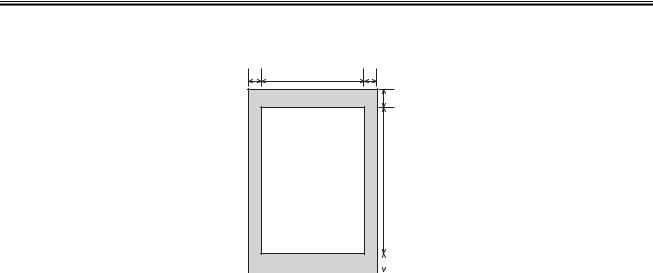
Chapter 1
[1] |
|
[2] |
[4] |
[3] |
|
[8] |
[5] |
[9] |
[6] |
|
|
|
|
|
[7] |
|
|
|
|
|
|
[10] |
|
|
|
|
|
|
|
F-1-3 |
|||
|
|
T-1-7 |
|||
[1] Paper leading edge |
[6] Effective printing length |
||||
[2] Left margin |
[7] Bottom margin |
||||
[3] Effective printing width |
[8] Printing drop out range |
||||
[4] Right margin |
[9] Printing range |
||||
[5] Top margin |
[10] Paper trailing edge |
||||
T-1-8
Item |
A4 |
Letter |
Legal |
Effective printing width |
206 mm |
212 mm |
212 mm |
Effective printing length |
290 mm |
272.4 mm |
348.6 mm |
Left margin |
5.0 mm |
5.0 mm |
5.0 mm |
Right margin |
5.0 mm |
5.0 mm |
5.0 mm |
Top margin |
5.0 mm |
5.0 mm |
5.0 mm |
Bottom margin |
5.0 mm |
5.0 mm |
5.0 mm |
1.2.6 System Requirements for Printer Driver
0008-8673
LaserBase MF5750 / LaserBase MF5730 / LaserBase MF5770
Operating System
Windows 98, Windows Me, Windows 2000 Professional, Windows XP
Computer
Any computer on whitch Windows 98, Windows Me, Windows 2000, or Windows XP runs properly.
Hardware Environment
-IBM or IBM-compatible PC
-CD-ROM drive or network environment with the access to CD-ROM -PC equipped with a USB port and the USB class driver installed
T-1-9
OS |
CPU |
RAM |
Available Free Disk Space |
|
|
Intel Pentium 90 MHz or |
32 MB of RAM, 64 |
At least 115 MB, 200MB or greater is |
|
Windows 98 |
MB or greater is |
|||
greater |
recommended |
|||
|
recommended |
|||
|
|
|
||
|
|
|
|
1-9

Chapter 1
OS |
CPU |
RAM |
Available Free Disk Space |
|
Windows Me |
Intel Pentium 150 MHz or |
32 MB of RAM, 64 |
At least 115 MB, 200MB or greater is |
|
MB or greater is |
||||
greater |
recommended |
|||
|
recommended |
|||
|
|
|
||
|
|
|
|
|
Windows 2000* |
Intel Pentium 133 MHz or |
64 MB of RAM, 128 |
|
|
greater, or compatible micro |
At least 115 MB, 200MB or greater is |
|||
MB or greater is |
||||
Professional |
processors (up to 2 |
recommended |
recommended |
|
|
processors are supported) |
|
||
|
|
|
||
Windows XP* |
Pentium Family 300 MHz or |
64 MB of RAM, 128 |
At least 115 MB, 200MB or greater is |
|
greater |
MB or greater is |
recommended |
||
|
recommended |
|||
|
|
|
*Log on as a user with adoministrator privileges is recommended.
1-10
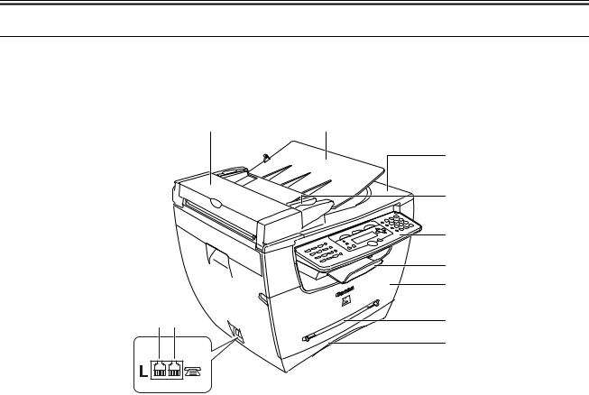
Chapter 1
1.3 Names of Parts
1.3.1 External View
0009-3468
LaserBase MF5750 / LaserBase MF5730 / LaserBase MF5770
<Front View>
[1] |
[2] |
[3]
|
[4] |
|
[5] |
|
[6] |
|
[7] |
[10][11] |
[8] |
|
[9] |
|
F-1-4 |
|
T-1-10 |
[1] ADF (Automatic Document Feeder) |
[7] Front cover |
[2] Document feeder tray |
[8] Multi-purpose feeder |
[3] Document output tray |
[9] Cassette |
[4] Document guides |
[10] Telephone line jack |
|
(MF5750/MF5770) |
[5] Operation panel |
[11] External device jack |
|
(MF5750/MF5770) |
[6] Output tray |
|
1-11

Chapter 1
[1]
[2]
F-1-5
T-1-11
[1]Platen glass cover
[2]Platen glass
<Rear View>
[1]
[5]
[2]
[3]
[4]
F-1-6
T-1-12
[1]USB port
[2]Face up cover
[3]Power socket
[4]Extension cover
[5]Ethernet port (MF5770)
1-12
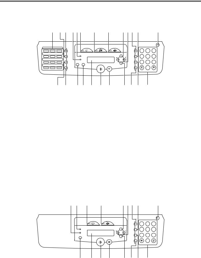
Chapter 1
1.3.2 Operation panel
0008-8675
LaserBase MF5750 / LaserBase MF5770
[1] |
[2] [3] [4] [5][6] |
[7] |
[8] |
[9][10][11][12] |
[13] |
01 |
02 |
03 |
1 |
2 |
3 |
04 |
05 |
06 |
4 |
5 |
6 |
07 |
08 |
09 |
7 |
8 |
9 |
10 |
11 |
12 |
|
0 |
|
[14] |
[15] |
[16] [17] |
[18] |
[19] |
[20] |
[21] |
[22] [23] |
[24] |
|
|
|
|
F-1-7 |
|
|
|
|
|
|
|
|
T-1-13 |
|
|
|
|
[1] One-touch dial keys |
|
|
[13] Energy Saver key |
|
||||
[2] Coded Dial key |
|
|
[14] Directory key |
|
|
|||
[3] Redial/Pause key |
|
|
[15] Hook key |
|
|
|
||
[4] In Use/Memory indicator |
|
[16] Status Monitor key |
|
|||||
[5] Alarm indicator |
|
|
[17] Clear key |
|
|
|
||
[6] COPY key |
|
|
|
[18] LCD |
|
|
|
|
[7] FAX key |
|
|
|
[19] Start key |
|
|
|
|
[8] SCAN key |
|
|
|
[20] Stop/Reset key |
|
|||
[9] Menu key |
|
|
|
[21] OK key |
|
|
|
|
[10] Cursor key |
|
|
|
[22] Collate/2on1 key |
|
|||
[11] Enlarge/Reduce key |
|
[23] Image Quality key |
|
|||||
[12] Exposure key |
|
|
[24] Numeric keys |
|
|
|||
1.3.3 Operation panel
0008-8676
LaserBase MF5730
[17] [2] |
[3] |
[4] |
[5] [6] [7] [8] |
[9] |
1 2 3
4 5 6
7 8 9
0
[10] |
[11] |
[12] |
[13] |
[14] |
[15] [16] |
[1] |
|
|
F-1-8 |
|
|
|
|
|
|
T-1-14 |
|
|
|
|
[1] Numeric keys |
|
[10] Status Monitor key |
|
|||
1-13

Chapter 1
[2] Alarm indicator |
[11] LCD |
[3] COPY key |
[12] Start key |
[4] SCAN key |
[13] Stop/Reset key |
[5] Menu key |
[14] OK key |
[6] Cursor keys |
[15] Collate/2on1 key |
[7] Enlarge/Reduce key |
[16] Image Quality key |
[8] Exposure key |
[17] In Use/Memory indicator |
[9] Energy Saver key |
|
1-14
Loading...