


Uni 5000F US
Bosch Uni 5000F US, Uni 171, Uni 207, Uni 5000F CA, Uni 256 Installation And Service Instructions Manual
C
Caution!
Observe the safety instructions of this installation
and maintenance manual before placing the boiler
in operation.
Danger!
If installation, adjustment, modification, operation or
maintenance of the heating system is carried out by
an unqualified person, this may result in danger to
life and limb or property damage.
The directions of this installation and maintenance
manual must be followed precisely.
Contact a qualified service company or service provider if support or additional information is required.
Caution!
The operating manual is a component of the technical documentation and must be handed over to the
operator of the heating system.
Discuss the content of this manual with the owner
or operator of the heating system to ensure that
they are familiar with all information required for
operation of the heating system. If the boiler will be
installed in Massuchussetts, it must be installed by
an installer or dealer who is registered there.
Installation and Service Instructions
Low-temperature oil and gas-fired boiler
Bosch Uni 5000F US/CA
171/207/256
6 720 648 032-00.1T
6 720 648 162- 2011/08 US/CA

2 | Contents
6 720 648 162 (2011/08)
Contents
1 Safety Considerations and Symbol
Descriptions 4
1.1 Regarding this Manual 4
1.2 Explanation of symbols 4
1.3 Observe the following Symbols 4
1.3.1 Installation Guidelines 5
1.3.2 Boiler Room Guidelines 5
1.4 Tools, Materials and Accessories 5
1.5 Disposal 6
2 Product description 7
2.1 Intended use 7
2.2 Certification and testing mark 7
2.3 Notes on installation and operation 7
2.4 Heating system water quality 7
2.5 Product description 7
2.6 Pack contents 8
2.7 Dimensions Specifications 9
2.7.1 Bosch Uni 5000F dimensions 9
2.8 Conditions for operation 10
2.8.1 General operating conditions 11
2.8.2 Conditions for the boiler room and the
environment 11
2.8.3 Combustion air supply conditions 12
2.8.4 Conditions, Fuel 12
2.8.5 burner selection 13
2.8.6 Conditions power supply 13
2.8.7 Conditions for hydraulic system and water
quality 14
3 Moving the boiler 15
4 Installing the boiler 16
4.1 Wall clearances 16
5 Boiler block assembly 17
5.1 Assembly when delivered in sections 17
5.1.1 Preparing boiler sections 17
5.1.2 Preparing push nippples and nipple ports 18
5.1.3 Preparing the intermediate section 18
5.1.4 Inserting the section sealing 19
5.1.5 Knock intermediate section into place 19
5.1.6 Boiler section alignment 19
5.1.7 Join boiler sections by the nipples at the top
and bottom boiler hub 20
5.1.8 Fitting the anchor rods 21
5.1.9 Fitting distribution tube and supply/return
header 22
5.1.10 Sealing the sensor well 23
5.1.11 Positioning the flue outlet 23
5.1.12 Sealing boiler hubs 23
5.2 Check for leaks 24
5.2.1 Preparing for a leak test). 24
5.2.2 Leak test 24
5.3 Installation when the boiler is supplied
assembled 24
5.4 Installation steps for disassembled and
assembled delivery 25
5.4.1 Fitting adjustable feet 25
5.4.2 Insert the flue gas baffle plates 25
5.4.3 Installing the burner door 26
5.4.4 Fitting the boiler jacket 26
5.5 Positioning and leveling the boiler 29
6 Installing the boiler 30
6.1 Flue pipe installation 30
6.1.1 Chimney venting 30
6.2 Fitting the water connections 31
6.2.1 Fitting the B-kit 31
6.2.2 Installation of boiler drain (included in B-Kit) 31
6.2.3 Installing system components 32
6.3 Filling the heating system and checking for
leaks 32
6.4 Mounting the burner 33
6.5 Connecting the fuel supply 34
6.6 Installing aquastat 34
6.7 Blocked vent switch (required in Canada) 34
6.8 Electrical connections 34
6.9 Jacket panel installation 35
7 Commissioning the heating system 36
7.1 Bringing the system up to operating pressure 36
7.2 Checking the safety valve 36
7.3 Preparing the heating system for operation 36
7.4 Starting up the burner 36
7.5 Notes on commissioning the burner 36
7.6 Raising flue gas temperature 37
7.6.1 Removing flue gas baffle plates 37
7.6.2 Removing the blocking plate 38
7.7 Manual reset high limit (STB) 38
7.8 Installing jacket panels 38
7.9 Commissioning log 39
8 Shutting down the heating system 40
8.1 Shutting down normally 40
8.2 Shutting down the heating system in an
emergency 40

Contents | 3
6 720 648 162 (2011/08)
9 Heating system servicing 41
9.1 Why is regular maintenance important? 41
9.2 Preparing the boiler for servicing 41
9.3 Cleaning the boiler 41
9.3.1 Cleaning the boiler with brushes 41
9.3.2 Wet cleaning (chemical cleaning) 42
9.4 Checking heating system operating pressure 42
9.5 Testing relief valve 43
9.6 Servicing and maintenance logs 44
10 Troubleshooting 47
11 Installation examples 48
12 Parts lists 51
13 Circuit diagrams 57
Index 66
4 | Safety Considerations and Symbol Descriptions
6 720 648 162 (2011/08)
1 Safety Considerations and Symbol Descriptions
1.1 Regarding this Manual
This document contains important information
regarding safe and proper installation, operation and
maintenance of the boiler.
The high tech Uni 5000F boiler is designated as a hot
water heating boiler.
The Installation and Maintenance Instructions are
directed to the installing contractor who has
professional knowledge regarding boiler installation and
maintenance.
1.2 Explanation of symbols
Signal words are used to indicate the seriousness of the
ensuing risk if measures for minimising damage are not
taken.
• Caution indicates that minor damage to property may
occur.
• Warning indicates that minor personal injury or severe
damage to property may occur.
• Danger means that severe personal injury may occur.
Very serious cases may result in death.
Notes contain important additional information.
Notes do not contain any warnings or information about
hazards or risks.
1.3 Observe the following Symbols
All applicable local, state, and national codes and
regulations must be observed for the installation of the
boiler:
• The local building code requirements regarding
placement, combustion air and venting and chimney
system must be followed.
• Follow applicable electrical code requirements.
• Follow the local code and standards regarding safe
boiler operation.
• The technical rules of the gas suppply company
regarding the connection of a gas burner to the gas
system.
Warnings are indicated by a warning
triangle and a grey background.
Notes are identified in the text by this
symbol. They are bounded by horizontal
lines above and below the text.
NOTICE
Use only original spare parts. Bosch can not
be held liable for damage caused by nonBosch parts.
NOTICE
Oil boilers: The boiler installation must be
performed by a qualified installer in
accordance with regulations put forth in
NFPA-31 Installation of Oil-Burning
Equipment. The installation must comply
with all local and national codes, regulations
and authorities having jurisdiction regarding
the installation of oil fired boilers.
For Canada refer to the guidelines of CSA/
CGA-B139 Installation Codes.
Gas boilers: The boiler installation must be
performed by a qualified installer in
accordance with regulations put forth in
ANSI Z223.1/NFPA-54, National Fuel Gas
Code. In Canada the requirements of CAN/
CSA B149, Installation Code for Gas Burning
Appliances and Equipment have be
observed.
Safety Considerations and Symbol Descriptions | 5
6 720 648 162 (2011/08)
1.3.1 Installation Guidelines
1.3.2 Boiler Room Guidelines
1.4 Tools, Materials and Accessories
For the installation and maintenance of the boiler you
will need typical tools used in this industry.
In addition, the following components are useful:
• Hand truck with strap or boiler cart.
• Wood blocking.
• Cleaning brushes and/or chemical cleaning agents for
wet cleaning.
If the boiler is delivered in sections, you will also require
the following:
• Compression tool 1.2 if the boiler is supplied in
sections (Æ compression tool documentation).
• Flat board.
• Cleaning agent.
• Installation kit (accessory)
• Steel hammer and wooden or rubber mallet
CAUTION: DANGER TO LIFE
from electric shock.
B Do not work on electrical components
unless you have the required
qualification.
B Do not work on electrical components
unless you have the required
qualification.
B Prior to opening the control: shut down
the power supply by turning off the
emergency shut-off switch or
disengaging the heating system circuit
breaker, and prevent from accidental
reactivation.
B Observe all applicable installation
guidelines.
CAUTION: DANGER TO LIFE
from explosion of volatile gases.
B Work on gas components must be carried
out by qualified and authorized
personnel only.
CAUTION: DANGER TO LIFE
from explosion of volatile gases.
If you notic a smell of gas there is a risk of
explosion.
B Extinguish all open flames.
B Do not smoke.
B Do not use lighting.
B Prevent sparks. Do not operate electrical
switches , including telephones, plugs or
doorbells.
B Close the main gas shut-off valve.
B Open windows and doors.
B Warn all occupants, but do not use
doorbells.
B Call gas company from outside the
building.
B If you hear gas escaping, immediately
leave the building, prevent others from
entering and notify police and fire
brigade from outside the building.
CAUTION: DANGER TO LIFE
from flue gas poisoning.
Insufficient combustion air can result in
dangerous operation if combustion air is
taken from indoors.
B Please observe that combustion air
openings are not reduced in size or
closed.
B Make sure that no mechanical air
openings or devices remove combustion
air from the boiler room such as central
vacuum systems, dryers and air
conditioning appliances.
B Make sure that the boiler is connected to
a chimney or horizontal venting system
that is capable of handling the slight
positive breeching pressure.
B If any of these problems have not been
corrected, the boiler must not be
operated.
B Make the end-user aware of these
guidelines and their potential danger.
CAUTION: FIRE DANGER
due to flammable or liquid materials.
B Make sure that flammable and liquid
materials are not stored in the close
vicinity of the boiler.

6 | Safety Considerations and Symbol Descriptions
6 720 648 162 (2011/08)
• Half- round bastard file
• Screwdriver (Philips and slotted head)
• Flat chisel
• Wrench SW 19, 36, 13, 19, 18, 24, 27 and Allen key
SW19
• Support wedge, flat iron
• Cleaning rags and cloth
• Fine emery cloth
• Wire brush
• 3-in-1 oil
• Cleaning agent, ruler, chalk, straight edge
• Blanking flange with vent facilitiy (for pressure test)
1.5 Disposal
B Please dispose of any trash in an environmentaly
friendly fashion.
B Please discard properly of any heating system related
components.
Product description | 7
6 720 648 162 (2011/08)
2 Product description
This installation and maintenance manual contains
important information for the safe and intended
installation, initial start-up and maintenance of this
boiler.
The special oil or gas-fired boiler is generally referred to
below as a boiler.
The installation and maintenance manual is provided for
technicians who have been trained and have experience
in working with heating systems and oil/gas fired
installations.
2.1 Intended use
The Bosch Uni 5000F is designed for central heating and
domestic hot water (DHW) systems, for instance in
residential homes or apartment buildings, or small
commercial applications.
2.2 Certification and testing mark
This appliance has been tested and certified to meet
rules and regulations in place for the US and Canadian
markets.
2.3 Notes on installation and operation
When installing and operating the heating system, it is
the installer's responsibility to meet all applicable
federal, state, and local codes.
2.4 Heating system water quality
Poor water quality can damage heating systems due to
scale formation and corrosion.
Please refer to Chapter 2.8.7, Tab. 9 for further details
of the water quality.
2.5 Product description
The boiler is a low-temperature for oil or gas combustion
appliance with automatic control panel or aquastat for
boiler water temperature.
The boiler consists of:
• Boiler block with insulation
• Boiler jacket
• Control panel or aquastat
The controls monitor and control all electrical boiler
components.
The boiler can alternatively be fitted with a simple
aquastat control.
The boiler jacket prevents heat loss and acts as a noise
insulator.
The boiler block transfers the heat generated by the
burner to the heating water. The insulation prevents
energy loss.
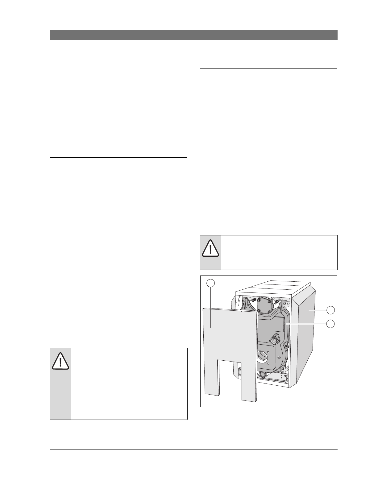
Suitable burners
Fig. 1 Boiler without burner
1 Burner door casing
2 Boiler jacket
3 Boiler block with insulation
CAUTION: Risk of system damage due to
unsuitable boiler water.
B If oxygen-permeable pipes are used, e.g.
for radiant heating systems, the systems
must be separated from the boiler by a
heat exchanger. Unsuitable heating
system water promotes sludge formation
and corrosion. This can result in heating
system malfunction and boiler damage.
CAUTION: Risk of system damage from use
of incorrect burner.
B Only the burner provided may be
employed with this boiler.
2
3
1
6 720 648 032-01.1T

8 | Product description
6 720 648 162 (2011/08)
2.6 Pack contents
Upon delivery, check that the packaging is complete and
undamaged.
Boiler as assembled block
Boiler in parts
Component Qty Packaging
Boiler block 1 1 pallet
1)
1) 1 pallet
Control panel or aquastat 1 1 box
Jacket Package:
• Boiler jacket
• Insulation
• Burner door, burner
door cover and
assembly equipment
2)
• Technical documents
B-Kit components:
• Supply manifold (11/4")
• 30 psi (2 bar) relief valve
• Boiler drain (¾ ")
• Pressure/temperature
gauge
• 90°-elbow (¾ ")
• Burner mounting studs
and washers
• Aquastat well (¾ ")
• Bushing 1" x ¾ "
• Plug 1"
2) The srew-in feet are in the burner door and burner door
cover package.
1
1
1
1
1
1 box on a
pallet
1 box
1)
1 box
1)
1 box
1)
1 plastic
package
1 package
Table 1 Package Contents
Component Qty Packaging
Front, center and back
sections
1 1 pallet
1)
1) 1 pallet
Control panel or aquastat 1 1 box
Jacket Package:
• Fittings
• Boiler jacket
• Insulation
• Burner door, burner
door cover and
assembly equipment
2)
• Technical documents
B-Kit components:
• Supply manifold (11/4")
• 30 psi (2 bar) relief valve
• Boiler drain (¾ ")
• Pressure/temperature
gauge
• 90°-elbow (¾ ")
• Burner mounting studs
and washers
• Aquastat well (¾ ")
• Bushing 1" x ¾ "
• Plug 1"
2) The srew-in feet are in the burner door and burner door
cover package.
1
1
1
1
1
1
1 box on a
pallet
1 box
1)
1 box
1)
1 plastic
package
1)
1 box
1)
1 plastic
package
1 package
Table 2 Package Contents

Product description | 9
6 720 648 162 (2011/08)
2.7 Dimensions Specifications
2.7.1 Bosch Uni 5000F dimensions
Fig. 2 Connections and dimensions (measurements in inches (mm))
VK = Boiler supply
RK = Boiler return
EL = Boiler drain (connection for drain valve)
VS = Hot water tank supply
Connections and dimensions:
6 720 648 032-02.1T
(781 mm)
(744 mm)
(686 mm)
(538 mm)
(72 mm)
(15 - 25 mm)
(150 mm)
(744 mm)
(107 mm)
(83 mm)
7
4
(302 mm)
5
8
(600 mm)
(881 mm)
Boiler model Unit Uni 171 Uni 207 Uni 256
Boiler sections Number 456
Heating capacity (gross output) Btu/hr
(kW)
171,000
(50)
207,000
(60)
256,000
(75)
Thermal output (net IBR output) Btu/hr
(kW)
149,000
(43)
180,000
(52)
223,000
(65)
Boiler water content Gal
(l) [Liter]
approx. 16.1
(61)
approx. 19.3
(73)
approx. 22.5
(85)
Gas capacity cu.ft.
(l) [Liter]
1.73
(68.8)
2.10
(85,1)
2.48
(101,4)
Oil firing rate GPH
(kg/h)
1.4
(4,5)
1.7
(5,4)
2.1
(6,7)
Maximum input rating Gas Btu/hr
(kW)
164,000
(48)
199,000
(58)
245,000
(72)
Hot gas resistance psi
(Pa)
0.0023−0.0078
(15,86 - 53,78)
Permissible max. supply temperature
1)
°F
(°C)
248
(120)
Allowable operating pressure psi
(bar)
58
(4)
Maximum time constant of thermostat and high limit
safety cut-out (STB)
s 40
Table 3 Technical data for boilers without burners

10 | Product description
6 720 648 162 (2011/08)
2.8 Conditions for operation
Maintaining the specified operating conditions will
enable the boiler to provide a high level of reliability and
long service life.
1) Limit (safety temperature limiter, STB)
Maximum permitted flow temperature = Safety limit (STB) - 32 °F (18 K)
Example: Safety limit (STB) = 212 °F (100 °C), maximum permitted flow temperature = 212 ° (100 °C) - 32 ° (18 K) = 180 °F
(82 °C)
The safety limit must meet the national regulations of the country concerned.
Boiler model Unit Uni 171 Uni 207 Uni 256
Boiler overall length (L) Inch
(mm)
31
(787)
35 ¾
(907)
40 ½
(1027)
Boiler block length (LK) Inch
(mm)
26 ¾
(680)
31 ½
(800)
36 ¼
(920)
Boiler section insert (width; height; depth) Inch
(mm)
− 18 1/8; 32 ¼ ; 5 7/8
(460 / 820 / 150)
Boiler block insert (width; height; depth) Inch
(mm)
18 1/8; 32 ¼ ; Length LK
(460 / 820)
Combustion chamber length Inch
(mm)
21 ½
(546)
26 ¼
(668)
31
(788)
Combustion chamber diameter Inch
(mm)
13 ¼
(337)
Burner door thickness Inch
(mm)
3 ¾
(95)
Burner pipe diameter (DB) Inch
(mm)
4 3/8
(112)
Hole circle diameter (DL) Inch
(mm)
5 7/8
(150)
Distance between boiler feet (FL) Inch
(mm)
18
(455)
22 ¾
(575)
27 ¼
(695)
Net weight1)– Lbs
(kg)
500
(227)
600
(272)
700
(317)
Table 4 Dimensions, weight and other data for boilers without burners
1) Incl. packaging material approx. 6-8 % more
CAUTION: Risk of system damage if
operating conditions are not maintained.
Irreversible damage to individual
components of the boiler as a whole or the
heating system may occur.
B The information on the rating plate is
binding and must be observed.

Product description | 11
6 720 648 162 (2011/08)
2.8.1 General operating conditions
2.8.2 Conditions for the boiler room and the environment
Operating conditions
Min. boiler water
temperature
Operating interruption
(complete boiler shutdown)
heating circuit with
heating circuit mixing valve
1)
Min. return temperature
In combination with control for variable low-temperature operating modes.
If heating zones or a boiler
circuit actuator cannot be
regulated via the control
device (for example pump
logic), an operating
temperature of 122 °F
(50 °C) must be reached
within 10 min of switching
the burner ON by
restricting the water
volume flow.
Possible if, after interruption of the
operation, there is at least 3 hours
heating operation.
not required but recommended with
low-temperature heating system
design 130/113 °F (55 / 45 °C)
Required with:
• Underfloor heating systems
• Systems with high water content:
> 115° gal/MBH (>15 l/kW)
(1 MBH = 100.000 Btu/hr)
not required, except for operation
with a modulating burner for:
• Oil combustion: 113 °F (45 °C)
• Gas combustion: 130 °F (55 °C)
In conjunction with a controls for constant boiler water temperatures or with supplementary external programmer and aquastat
150 °F
2)
(65 °C2) possible if, after interruption of the
operation, there is at least 3 hours
heating operation
required Required with:
• Systems with high water content
> 115 gal/MBH: 130 °F (15 l/kW:
55 °C)
• Operation with a modulating
burner: 130 °F (55 °C)
Table 5 General operating conditions
1) A heating circuit with a mixing valve improves controllability and is specifically recommended for systems with several heating
zones.
2) Boiler water temperature control setting: when the boiler is in ON mode, the minimum boiler water temperature in the boiler must
be reached within 10 minutes, e.g. by flow rate limitation, and maintained as the minimum temperature.^
Operating conditions Notes – Requirement in greater detail
Temperature in the boiler room +40 (+5 °C) to
+104 °F (+40 °C)
relative humidity max. 90 % No condensation or precipitation inside the boiler room
Dust/airborne particles − Excessive dust inside the boiler room must be avoided when the boiler is operating, e. g.:
• Dust from building work
Combustion air supplied from outside must not be excessively loaded with dust or
airborne particles; if necessary, air filters should be fitted in case:
• Air supply contaminated with dust from dirt roads and paths.
• Air supply contaminated with dust from production and processing facilities, e. g.
quarries, mines, etc.
• Airborne particles from thistles and similar
Halogenated-hydrocarbon
compounds
− The combustion air must be free from halogenated-hydrocarbon compounds.
• Identify the source of halogen-hydrocarbon compounds and seal it off. Where this is
impossible, route combustion air from areas that are not contaminated by halogen-
hydrocarbon compounds.
Table 6 Boiler room and ambient conditions

12 | Product description
6 720 648 162 (2011/08)
2.8.3 Combustion air supply conditions
2.8.4 Conditions, Fuel
Fans that extract air from the
boiler room.
− During burner operation, no mechanical air handling equipment may be operated that could
extract combustion air from the boiler room, e.g.:
• Exhaust hood
• Tumble dryer
• Ventilation equipment
Small animals − Prevent small animals from entering the boiler room, particularly through the air inlet vents
– by fitting them with screens.
Fire safety − Maintain clearances between the boiler and flammable materials in accordance with local
regulations. A minimum clearance of 16" is required. Never store flammable materials or
liquids in the vicinity of the boiler.
Flooding − In case of an acute risk of flooding, disconnect the boiler in time from its fuel and power
supply before water enters the room. Any components or control equipment, which came in
contact with flood water, must be replaced before re-commissioning.
Operating conditions Notes – Requirement in greater detail
Table 6 Boiler room and ambient conditions
Operating conditions
Boiler output (in case of
multi-boiler systems = total output)
Ventilation air cross-section in square inches
(unrestricted aperture)
Air intake flow cross-section for
combustion air drawn from
outside (divided between max. 2
apertures)
< 170,000 Btu/hr
(< 50 kW)
At least 23.25 square inches (150 cm
2
)
> 170,000 Btu/hr
(> 50 kW)
At least 23.25 (150 cm
2
) square inches and also 0.91 square inches
(6 cm
2
) per 10,000 Btu/hr (3 kW),
that is above 170,000 Btu/hr (50 kW)
Table 7 Observe national regulations for boilers which draw their air supply from the boiler room.
Operating conditions Notes – Requirement in greater detail
Permissible fuels for boilers
without integral burners
− This boiler can be operated with following fuels. Select a burner that is suitable for one of
these fuel types:
• Fuel oil in accordance with the burner specification. If a poorer quality oil (kinematic
viscosity > 0.0093 sq in/sec (> 45.5 s Sayboldt) at 68 °F) is used, the maintenance and
cleaning periods must be reduced. In that case, carry out maintenance and cleaning
procedures at least twice a year.
• Natural gas in accordance with the burner specification
• LPG in accordance with the burner specification
Contamination − Free of contaminants (for example dust, mist, humidity), i. e. a constant operation will not
lead to accumulation of deposits, in valves, strainers and filters and could lead to service
calls.
Table 8 Fuels
Product description | 13
6 720 648 162 (2011/08)
2.8.5 burner selection
Oil burner
Gas burner
2.8.6 Conditions power supply
boiler size burner manufacturer burner model nozzle pump pressure
Uni 171 Riello 40F5 1.25 x 80 B 145 Psi
(10 bar)
Uni 207 40F10 1.50 x 80 W 145 Psi
(10 bar)
Uni 256 40F10 1.75 x 45 B 185 Psi
(12,75 bar)
Uni 171 Bekett AFG H 1.10 x 45 ES 175 Psi
(12 bar))
Uni 207 CF375 H 1.35 x 45 ES 170 Psi
(11,7 bar)
Uni 256 CF375 H 1.75 x 45 ES 140 Psi
(9,6 bar)
Uni 171 Carlin 99 FRD D 1.25 x 60 B 150 Psi
(10,3 bar)
Uni 207 99 FRD D 1.50 x 60 B 150 Psi
(10,3 bar)
Table 9 Oil burner
boiler size
burner
manufacturer
burner model
orifice manifold pressure
natural propane natural propane
Uni 171 Riello 40G200 2.00 mm 1.30 mm 1.75" WC
(436 Pa)
2.60" WC
(647 Pa)
Uni 207 40G400 2.20 mm 1.50 mm 0.95" WC
(236.5 Pa)
1.30" WC
(323.5 Pa)
Uni 256 40G400 2.20 mm 1.50 mm 1.30" WC
(323.5 Pa)
1.70" WC
(423.5 Pa)
Table 10 Gas burner
Operating conditions Notes – Requirement in greater detail
Power supply voltage 110−120 V Observe the voltage range of the burner and controls used. The outer casing/boiler must be
grounded for safety reasons and in order to function correctly.
Fuse 10 A
Frequency 60 Hz Sinusoidal voltage curve
Protection − IP 40 (protected against contact by entry of foreign objects > 0.04 inches Ø
(> 1 mm Ø ), no water proofing)
Table 11 Power supply

14 | Product description
6 720 648 162 (2011/08)
2.8.7 Conditions for hydraulic system and water quality
Operating conditions Notes – Requirement in greater detail
Operating pressure
(overpressure)
15–58psi
(1,0 - 4,0 bar)
Maximum 30 psi (2 bar) with the supplied safety valve.
Permissible site test pressure 45 – 75 psi
(3,1 - 5,2 bar)
Safety temperature limitation by
TR temperature control
122 – 194 °F
(50 - 90 °C)
Safety temperature limitation by
manual reset high limit (STB)
212 – 248 °F
(100 - 120 °C)
On some controls adjustable on site from 212 (100 °C) to 248 °F (120 °C).
Water quality − The heating system may only be filled and topped up with wate r of domestic water quality.
We recommend a pH value of 8.2 – 9.5.
Table 12 System configuration and water quality
Moving the boiler | 15
6 720 648 162 (2011/08)
3 Moving the boiler
This chapter details how to move the boiler safely.
CAUTION: Risk of system damage from
impact.
Fragile components could be damaged.
B Observe the transport instructions on the
packaging.
CAUTION: Risk of injury if load is
inadequately secured during
transportation.
B Use suitable means of transportation,
e.g. the Bosch boiler hand truck with
strap.
B Secure the load against falling.
Protect boiler connections from damage
and dirt if the boiler is not installed
immediately.
Dispose of packaging in an environmentally
responsible manner.
16 | Installing the boiler
6 720 648 162 (2011/08)
4 Installing the boiler
This chapter describes how to install and place the
boiler in the boiler room.
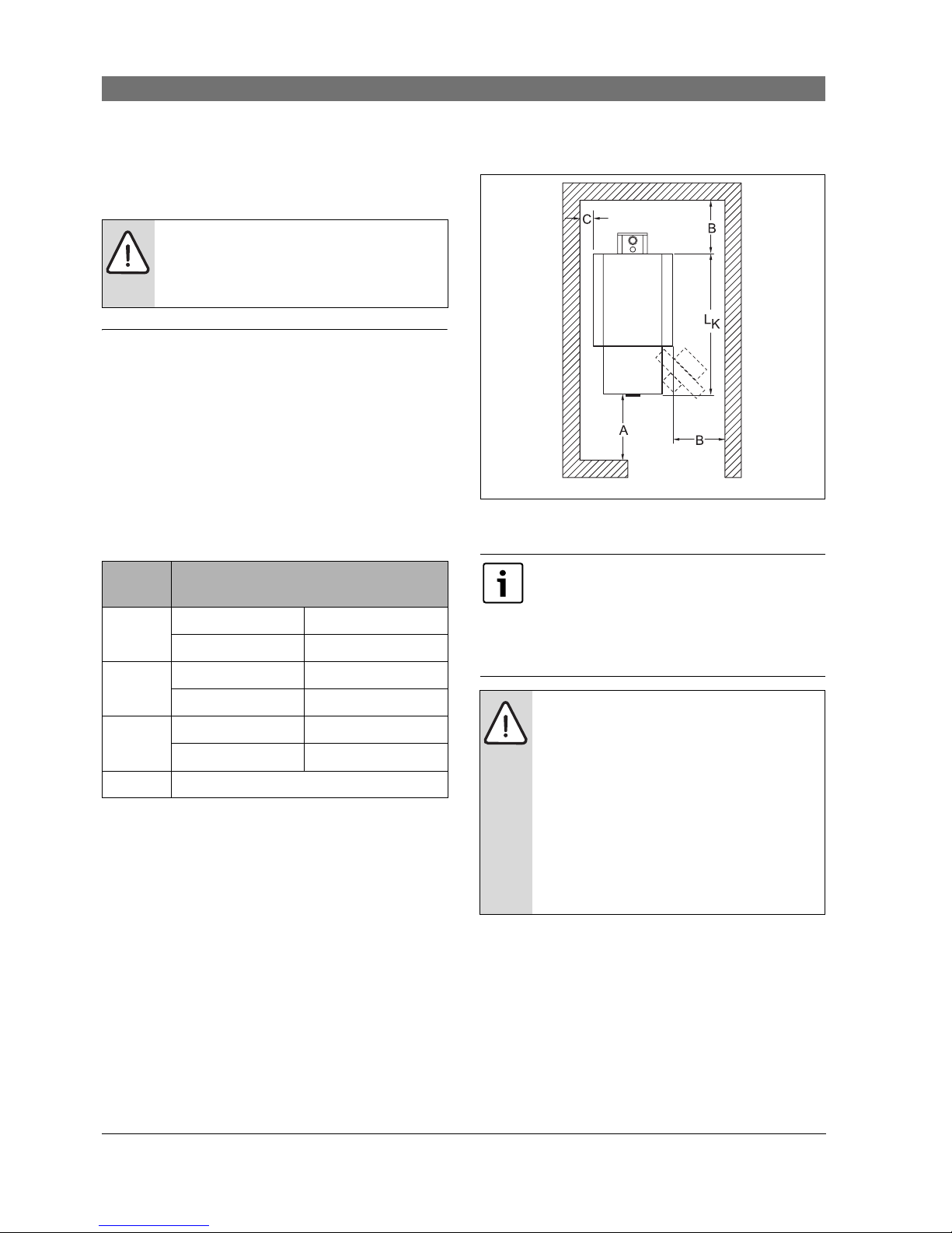
4.1 Wall clearances
Position the boiler with the recommended wall
clearances. Reducing the minimum clearances makes
the boiler more difficult to access during installation,
maintenance and cleaning.
The boiler base or foundation must be perfectly flat and
level.
The burner door is factory-fitted with the hinges on the
right. The burner door can be converted to open to the
left.
Fig. 3 Boiler room clearances (boiler positioned on the
l.h. or r.h. side)
CAUTION: Risk of system damage from
freezing.
B Install the heating system in a frost-free
room.
Dimension
Wall clearance
A Recommended 51 1/8" (1300 mm)
minimum 39 3/8" (1000 mm)
B Recommended 27 ½ " (700 mm)
minimum 15 ¾ " (400 mm)
C Recommended 15 ¾ " (400 mm)
minimum 3 7/8" (100 mm)
L
K
see "Technical Data" chapter
Table 13 Recommended and minimum wall clearances
(dimensions in inches).
The boilers are designed for a side clearance
of 6" (150 mm).
Where applicable, allow extra wall
clearances for additional components such
as DHW tank, pipe connections, flue gas
silencer or other flue components, etc.
CAUTION: Risk of fire from flammable
materials or liquids.
B Clearances less than 6" (150 mm) must
comply with local and statutory codes.
B Make sure that there is a sufficient
clearance between combustible
materials and the chimney connection as
specified by NFPA 31 (distance of 18 "
(460 mm)).
B The floor must comply with the
requirements of NFPA 31.
6 720 648 032-03.1T

Boiler block assembly | 17
6 720 648 162 (2011/08)
5 Boiler block assembly
The on-site installlation is carried out using individual
sections if, because of physical limitations, a boiler block
cannot be assembled as a complete unit.
For installation of boiler supplied fully assembled
(Æ Chapter 7.3, page 36).
Fig. 4 Boiler block in the assembled state
1 Foundation/installation location
2 Drain
3 Back section
4 Flue outlet
5 Connecting block
6 Central sections
7 Anchor rods
8 Burner door
9 Front section
5.1 Assembly when delivered in sections
B Assembly all boiler sections in accordance with the
following instructions and diagrams.
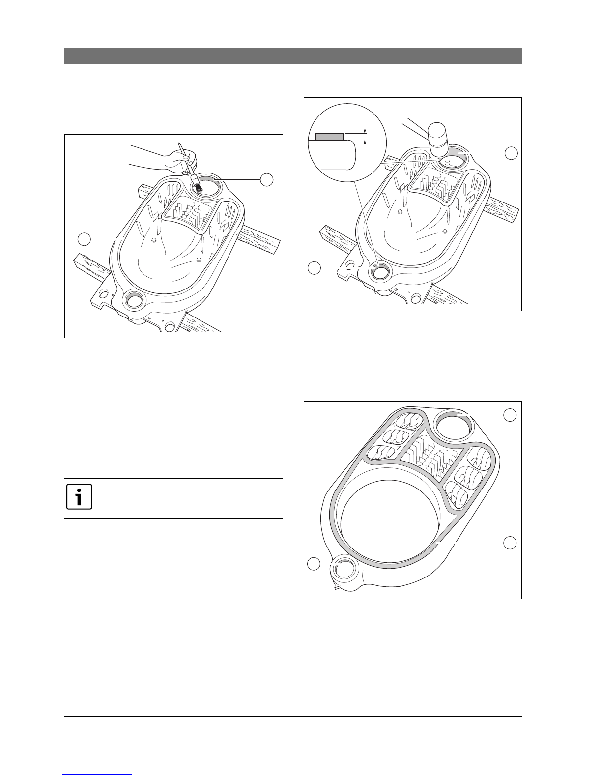
5.1.1 Preparing boiler sections
B Position the rear section onto two wood blocks.
B Clean the boiler hubs with sandpaper and a rag.
B Remove any burrs with a file.
B Clean the packing spring or packing groove with a
wire brush and rag.
Fig. 5 Remove burrs
1 Boiler hubs
2 Sealing spring
3 Back section
4 Wood blocks
B Clean the hub sealing faces with a rag soaked in
cleaning agent.
CAUTION: Risk of injury by not securing the
boiler adequately during transport.
B Use only suitable means for
transportation, e.g. a trolley with strap, a
stair or step trolley.
B Secure the load against falling.
6 720 648 032-04.1T
8
9
7
1
2
3
4
5
6 7
CAUTION: Risk to heal th o r dan ger o f burns
due to released vapors and easily flammable
cleaning agents.
B When using red lead putty, adhesives and
solvents ensure adequate ventilation
inside the installation room.
B When using solvents, avoid open flames,
incandescence and sparks.
B Please observe the manufacturer‘s
handling and safety instructions.
1
4
2
1
3
6 720 648 032-05.1T
18 | Boiler block assembly
6 720 648 162 (2011/08)
B Evenly coat the boiler hub sealing faces with red lead
putty.
B Coat the packing spring or packing groove with
adhesive (adhesive base).
Fig. 6 Coat boiler hubs with red lead putty
1 Sealing spring
2 Boiler hub sealing face
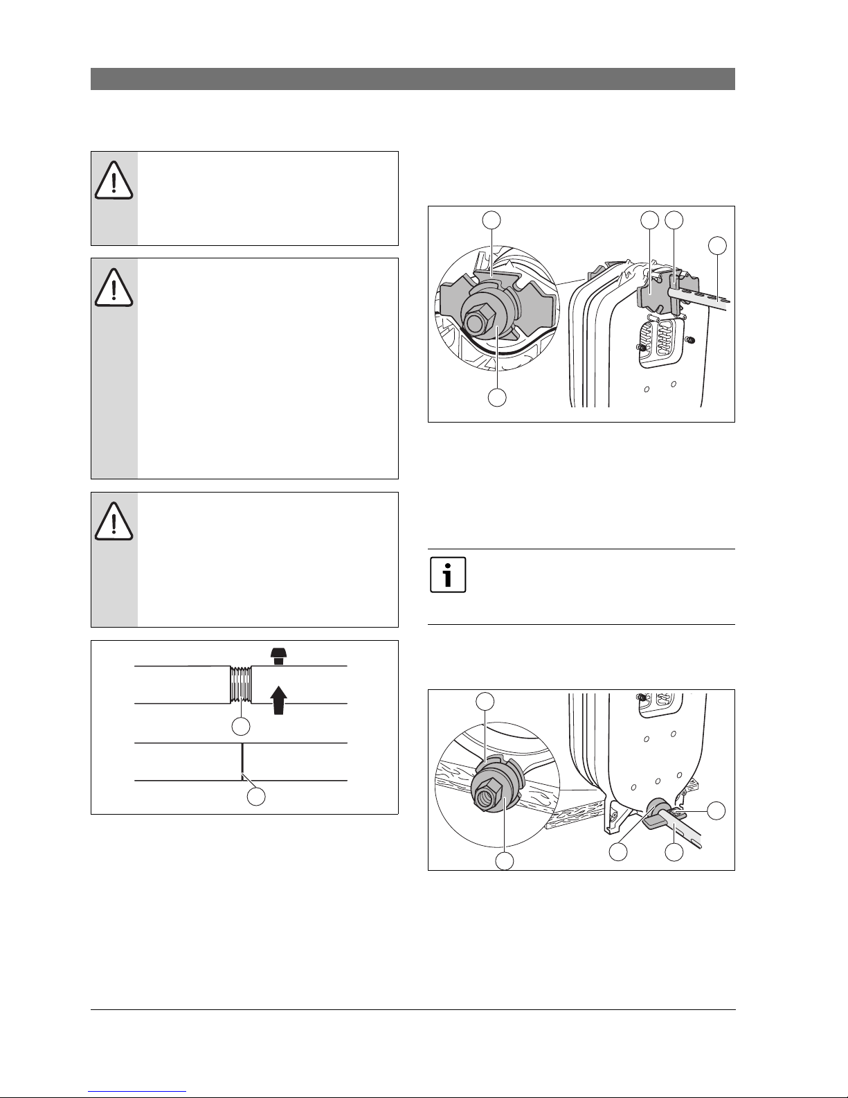
5.1.2 Preparing push nippples and nipple ports
B Clean the nipples with a cloth soaked in cleaning
agent.
B Evenly coat the nipples with red lead putty.
B Place nipple straight in the top and bottom boiler hub
of the back section and hammer in a crosswise
pattern.
B Remove any burrs with a file.
Fig. 7 Driving nipples home
1 Nipple in bottom boiler hub
2 Nipple in the upper boiler hub
5.1.3 Preparing the intermediate section
B Prepare the central section in the same way as the
back section (Æ Chapter 5.1.1, page 17).
Fig. 8 Preparing the central section
1 Boiler hub sealing face
2 Packing grooves
After driving in the nipple leave it projecting
approx. 1 1/8" (30 mm) from the boiler hub.
6 720 648 032-06.1T
1
2
1 1/8
1
2
6 720 648 032-07.1T
30 mm
6 720 648 032-08.1T
1
1
2

Boiler block assembly | 19
6 720 648 162 (2011/08)
5.1.4 Inserting the section sealing
B Unroll the required length of section sealing from the
roll supplied.
B Peel the backing paper from the sealing rope as you
insert the cord into the packing groove.
B Insert the flexible sealing rope into the packing groove
starting in the upper boiler hub area, and lightly press
in.
B Overlap sealing rope 3/4" (20 mm) at the joins and
press in well.
Fig. 9 Inserting the section sealing rope
5.1.5 Knock intermediate section into place
B Turn the intermediate section around and locate with
the upper and lower boiler hubs on the nipples of the
rear section.
B Drive the intermediate section onto the rear section
using a wood or a rubber mallet.
Fig. 10 Knock intermediate section into place
1 Wood or rubber mallet
2 Rear section
5.1.6 Boiler section alignment
B Position the partly assembled block of two boiler
sections.
B Position a flat board underneath the center section so
that the boiler block is slightly tilted for the
continuing assembly.
Fig. 11 Installing boiler block section
1 Center section
2 Flat board
CAUTION: System damage from leaking
boiler sections.
B Never stretch the sealing rope during
application to ensure that the faces
between the boiler sections are sealed
correctly.
B Carefully insert the sealing rope into the
boiler section packing grooves.
6 720 648 032-09.1T
CAUTION: Risk of injury from inadequately
secured boiler sections.
B Secure the boiler block section against
tipping.
6 720 648 032-10.1T
2
1
1
2
6 720 648 032-11.1T
20 | Boiler block assembly
6 720 648 162 (2011/08)
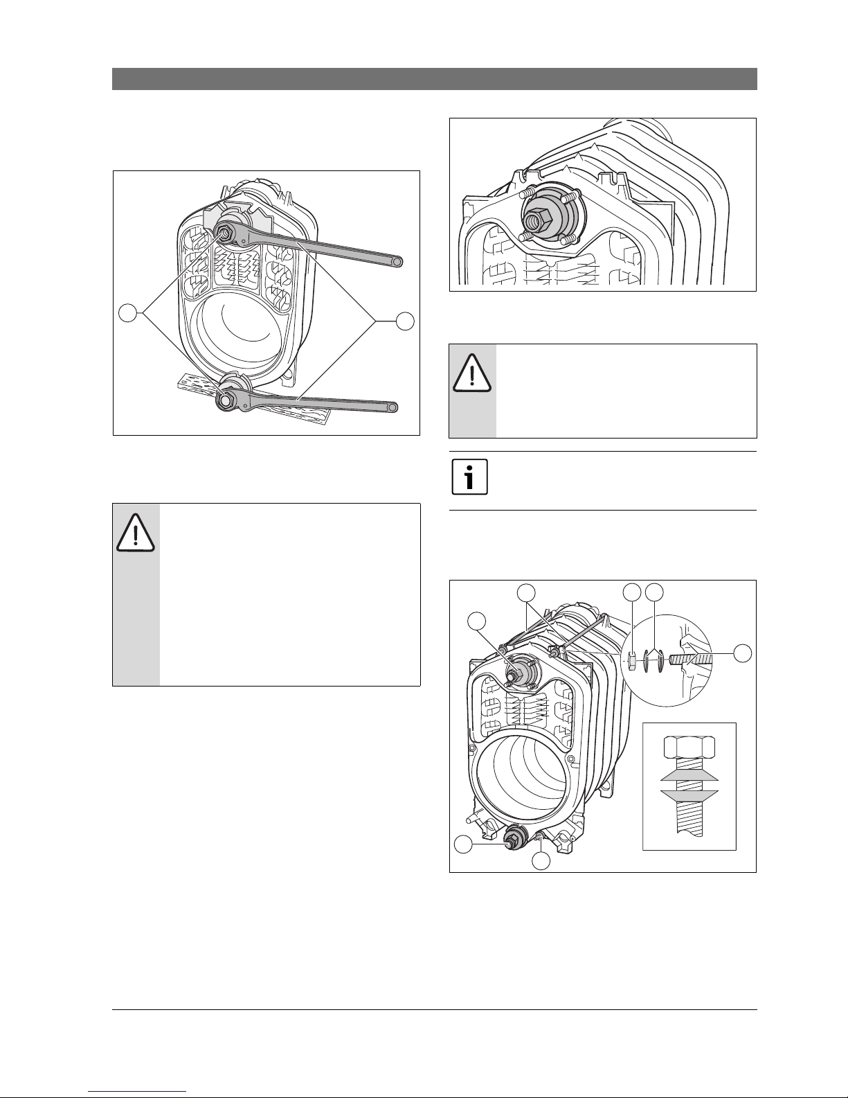
5.1.7 Join boiler sections by the nipples at the top
and bottom boiler hub
Fig. 12 Making the pull rod threaded connection
1 Pull rod threaded connection (incorrectly joined)
2 Pull rod threaded connection (correctly joined)
B Push on pull rod each through the lower and the
upper boiler hub of the partly assembled block.
B Push the auxiliary flange onto the pull rods of the
lower and upper boiler hubs.
B Push the mating flange onto the pull rod of the lower
and upper boiler hubs, and secure with the respective
wedges.
B Thread the compression units onto the pull rod
threads.
Fig. 13 Compression tool assembled at the upper boiler
hub
1 Auxiliary flange (Ø 5 3/8" x 1" (Ø 135 x 25 mm) top boiler hub)
2 Compression unit
3 Mating flange (
Ø 5 3/8" x 1" (Ø 135 x 25 mm) top boiler hub)
4 Wedge
5 Pull rod in the upper boiler hub
B Hold the pull rods at the center of the boiler hubs and
slightly draw together the compression tools using
the compression unit.
Fig. 14 Compression tool assembled at the lower boiler
hub
1 Auxiliary flange h (Ø 3 1/8" x 1" (Ø80x25mm))
2 Compression unit
3 Mating flange (
Ø 3 1/8" x 1" (Ø80x25mm)bottom boiler hub)
4 Pull rod in the bottom boiler hub
5 Wedge
CAUTION: Boiler damage due to unsuitable
compression tool.
B Use only the compression tool size 1.2
(Æ documents for compression tool)
suitable for the boiler.
CAUTION: Compression tool damage
The compression tool may be damaged or
destroyed, if you compress pull rods with
loose threaded connections.
B Check the threated connection of the pull
rods after every compression, and
tighten, if required. The pull rod is
correctly positioned if it is fully inserted
and no thread is showing.
B Keep the thread of the compression tool
clean. Dirty threads can damage the
compression tool during compression.
CAUTION: Boiler damage due to incorrectly
positioned auxiliary flange.
Leaks may occur if the auxiliary flange sits in
the packing spring/groove of the boiler
section during the compression process.
B Ensure that the auxiliary flange lies level
on the boiler hubs.
6 720 648 032-12.1T
1
2
Push the compression units far enough onto
the pull rod threads that two thread
windings protrude from the compression
units.
1 3 4
5
2
6 720 648 032-13.1T
6 720 648 032-14.1T
1
2
3
4
5
Boiler block assembly | 21
6 720 648 162 (2011/08)
B Set both ratchet wrenches on the clamping nuts of
the compression units and press the boiler sections
together by evenly tightening the nuts.
Fig. 15 Positioning ratchet
1 Clamping nut
2 Ratchet
B Release and remove the compression tool.
B Hammer the nipples into the assembled boiler block
(Æ Chapter 5.1.2, page 18).
B Prepare all other intermediate sections as described
above and join them at the nipples.
Fitting the front section
Due to the threaded studs, do not use the auxiliary
flange at the front of the upper boiler hub when
assembling the front section.
B Push the pull rod together with the compression unit
through the upper boiler hub.
B Carry out all other steps as described
(Æ Chapter 5.1.7, page 20).
Fig. 16 Fit the compression tool to the front section
5.1.8 Fitting the anchor rods
B Insert the anchor rods with spring washers into the
case cams on the l.h. and r.h. side as well as adjacent
to the lower boiler hubs.
Fig. 17 Ankerstangen montieren
1 Compression tool
2 Anchor rods
3 Nut
4 Spring washers
5 Cast lugs
A Spring washer arrangement
CAUTION: Boiler damage due to leaking
boiler sections.
B For each compression procedure ensure
thatno more than one nipple joint (one
nipple joint comprises two sections) is
compressed.
B Never jam nipples into the boiler hubs of
the boiler section.
B Stop pressing the sections together
when the boiler hubs meet.
1
2
6 720 648 032-15.1T
CAUTION: System damage due to incorrect
spring washer assembly.
B Ensure that the spring washers are
arranged opposite each other on the
anchor rods.
Insert the anchor rods before removing the
compression tool.
Never remove the compression tool first.
6 720 648 032-16.1T
2
3
4
2
1
1
5
6 720 648 032-17.1T
A
 Loading...