


Dinion Infrared Imager
VEI-Series
en User Manual

Dinion Infrared Imager |
Table of Contents | en |
3 |
|
|
|
|
|
Table of Contents |
|
|
|
|
|
|
|
1 |
Safety |
|
5 |
1.1 |
Safety precautions |
|
5 |
1.2 |
Important safety instructions |
|
5 |
1.3 |
Important notices |
|
6 |
1.4 |
FCC & ICES compliance |
|
9 |
1.5 |
CSA certification - Disclaimer |
|
10 |
1.6 |
Bosch notices |
|
11 |
|
|
|
|
2 |
Description |
|
12 |
2.1 |
Unpacking |
|
12 |
2.1.1 |
Parts Included with the Product |
|
13 |
2.1.2 |
User-supplied Parts |
|
13 |
2.1.3 |
Required Tools (User-Supplied) |
|
13 |
|
|
|
|
3 |
Planning |
|
14 |
3.1 |
Pre-installation Checklist |
|
16 |
|
|
|
|
4 |
Installation |
|
18 |
4.1 |
Overview of Installation Steps |
|
18 |
4.2 |
Mount the Junction Box |
|
19 |
4.3 |
Route Wires and Attach Connectors |
|
20 |
4.3.1 |
About the Coaxial Cable |
|
21 |
4.3.2 |
About Alarm Output Connections |
|
22 |
4.4 |
Attach Pendant Arm to Junction Box |
|
23 |
|
|
|
|
5 |
Manual Camera Settings |
|
24 |
5.1 |
Adjusting Focus, Focal Length, Pan, and Tilt |
24 |
|
5.1.1 |
Accessing the Rear Controls |
|
24 |
5.1.2 |
Adjusting the Focus and Focal Length |
|
25 |
5.1.3 |
Making Pan Adjustments |
|
26 |
5.1.4 |
Making Tilt Adjustments |
|
26 |
5.2 |
Adjusting Angle of LED Tilt and Width of Illumination Beam |
27 |
|
5.2.1 |
Adjusting the Angle of LED Tilt |
|
27 |
5.2.2 |
Adjusting the Illumination Beam Width |
|
28 |
Bosch Security Systems, Inc. |
User Manual |
F.01U.263.417 | 3.0 | 2012.01 |

4 en | Table of Contents |
Dinion Infrared Imager |
|
|
|
|
|
|
|
6 |
Operation via Keyboard and OSD Menus |
30 |
6.1 |
Menus |
30 |
6.1.1 |
Top level menus |
30 |
6.1.2 |
Menu navigation |
30 |
6.2 |
Pre-defined modes |
31 |
6.3 |
Camera control communication (Bilinx) |
32 |
6.4 |
Main menu structure |
33 |
6.4.1 |
Mode submenu |
33 |
6.4.2 |
ALC submenu |
34 |
6.4.3 |
Shutter/AGC submenu |
35 |
6.4.4 |
Day/Night submenu |
37 |
6.4.5 |
Illuminator submenu |
38 |
6.4.6 |
Enhance / Dynamic Engine submenu |
39 |
6.4.7 |
Color submenu |
40 |
6.4.8 |
VMD submenu |
41 |
6.5 |
Install menu structure |
42 |
6.5.1 |
Lens Wizard submenu |
42 |
6.5.2 |
Language submenu |
43 |
6.5.3 |
Privacy Masking submenu |
43 |
6.5.4 |
Synchronization submenu |
44 |
6.5.5 |
Alarm Output submenu |
44 |
6.5.6 |
Connections submenu |
45 |
6.5.7 |
Test Signals submenu |
45 |
6.5.8 |
Camera ID submenu |
46 |
6.5.9 |
Defaults submenu |
46 |
|
|
|
7 |
Maintenance |
47 |
7.1 |
Repairs |
47 |
7.2 |
Transfer and Disposal |
47 |
|
|
|
8 |
Technical Data |
48 |
|
|
|
|
Index |
50 |
F.01U.263.417 | 3.0 | 2012.01 |
User Manual |
Bosch Security Systems, Inc. |

Dinion Infrared Imager |
Safety | en |
5 |
|
|
|
1Safety
1.1Safety precautions
DANGER!
High risk: This symbol indicates an imminently hazardous situation such as “Dangerous Voltage” inside the product. If not avoided, this will result in an electrical shock, serious bodily injury, or death.
WARNING!
Medium risk: Indicates a potentially hazardous situation.
If not avoided, this could result in minor or moderate bodily injury.
CAUTION!
Low risk: Indicates a potentially hazardous situation.
If not avoided, this could result in property damage or risk of damage to the unit.
NOTICE!
This symbol indicates information or a company policy that relates directly or indirectly to the safety of personnel or protection of property.
1.2Important safety instructions
Read, follow, and retain all of the following safety instructions. Heed all warnings on the unit and in the operating instructions before operating the unit.
1.Clean only with dry cloth.
2.Do not block any ventilation openings. Install in accordance with manufacturer’s instructions.
3.Do not install near any heat sources such as radiators, heat registers, stoves or other apparatus (including amplifiers) that produce heat.
Bosch Security Systems, Inc. |
User Manual |
F.01U.263.417 | 3.0 | 2012.01 |
6 |
en | Safety |
Dinion Infrared Imager |
|
|
|
4.Protect the power cord from being walked on or pinched particularly at plugs, convenience receptacles, and the power where they exit from the apparatus.
5.Use only attachments/accessories specified by the manufacturer.
6.Refer all servicing to qualified service personnel. Servicing is required when the apparatus has been damaged in a way, such as power-supply cord or plug is damaged, liquid has been spilled or objects have fallen into the apparatus, does not operate normally, or has dropped. When servicing, power shall be disconnected.
1.3Important notices
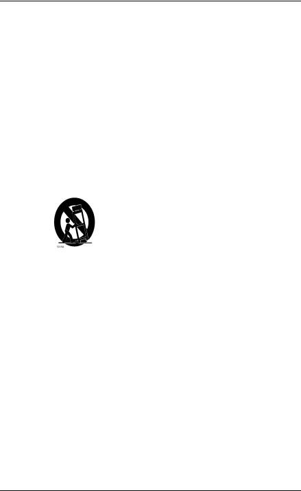
Accessories - Do not place this unit on an unstable stand, tripod, bracket, or mount. The unit may fall, causing serious injury and/or serious damage to the unit. Use only with the cart, stand, tripod, bracket, or table specified by the manufacturer. When a cart is used, use caution and care when moving the cart/ apparatus combination to avoid injury from tipover. Quick stops, excessive force, or uneven surfaces may cause the cart/unit combination to overturn. Mount the unit per the manufacturer's instructions.
All-pole power switch - Incorporate an all-pole power switch, with a contact separation of at least 3 mm in each pole, into the electrical installation of the building. If it is needed to open the housing for servicing and/or other activities, use this all-pole switch as the main disconnect device for switching off the voltage to the unit.
Camera signal - Protect the cable with a primary protector if the camera signal is beyond 140 feet, in accordance with
NEC800 (CEC Section 60).
F.01U.263.417 | 3.0 | 2012.01 |
User Manual |
Bosch Security Systems, Inc. |

Dinion Infrared Imager |
Safety | en |
7 |
|
|
|
CAUTION!
This product has been tested according to standard CIE/IEC 62471:2006 “Photobiological safety of lamps and lamp systems” and found to meet Risk Group 2 for exposure limit 4.3.7 “Infrared radiation hazard exposure limits for the eye.” For other hazard exposure limits, the product was found to be exempt. Risk Group 2 is characterized in the standard as “products generally do not pose a realistic optical hazard if aversion responses limit the exposure duration or where lengthy exposures are unrealistic.” Since there is no aversion response for IR, avoid eye exposure. Risk Group 2 sources do not pose an infrared radiation hazard for the eye within 10 s at distances beyond 200 mm or 8 inches. The Exposure Hazard Value for the product (ratio of the Exposure level to the Exposure limit) is up to 10 at a test distance of 200 mm (8 inches). The Hazard Distance (distance beyond which the product falls into the exempt/safe group) is at most 640 mm (25 inches). Note that typical use cases are well beyond the Hazard Distance.When servicing the unit, physically disconnect the power supply to avoid possible IR exposure to the eyes. If physical disconnection is not possible, use appropriate shielding to block the LED panel or use eye protection with a transmission of 10% or less at a wavelength of 850 nm.
Coax grounding:
–Ground the cable system if connecting an outside cable system to the unit.
–Connect outdoor equipment to the unit's inputs only after this unit has had its grounding plug connected to a grounded outlet or its ground terminal is properly connected to a ground source.
–Disconnect the unit's input connectors from outdoor equipment before disconnecting the grounding plug or grounding terminal.
–Follow proper safety precautions such as grounding for any outdoor device connected to this unit.
Bosch Security Systems, Inc. |
User Manual |
F.01U.263.417 | 3.0 | 2012.01 |

8 |
en | Safety |
Dinion Infrared Imager |
|
|
|
U.S.A. models only - Section 810 of the National Electrical Code, ANSI/NFPA No.70, provides information regarding proper grounding of the mount and supporting structure, grounding of the coax to a discharge unit, size of grounding conductors, location of discharge unit, connection to grounding electrodes, and requirements for the grounding electrode.
Disposal - Your Bosch product was developed and manufactured with high-quality material and components that can be recycled and reused. This symbol means that electronic and electrical appliances, which have reached the end of their working life, must be collected and disposed of separately from household waste material. Separate collecting systems are usually in place for disused electronic and electrical products. Please dispose of these units at an environmentally compatible recycling facility, per European Directive 2002/96/EC.
Electronic Surveillance - This device is intended for use in public areas only. U.S. federal law strictly prohibits surreptitious recording of oral communications. Environmental statement - Bosch has a strong commitment towards the environment. This unit has been designed to respect the environment as much as possible.
Fuse rating - For protection of the device, the branch circuit protection must be secured with a maximum fuse rating of 16A. This must be in accordance with NEC800 (CEC Section 60). Moving - Disconnect the power before moving the unit. Move the unit with care. Excessive force or shock may damage the unit and the hard disk drives.
Outdoor signals - The installation for outdoor signals, especially regarding clearance from power and lightning conductors and transient protection, must be in accordance with NEC725 and
NEC800 (CEC Rule 16-224 and CEC Section 60).
Permanently connected equipment - Incorporate a readily accessible disconnect device external to the equipment.
F.01U.263.417 | 3.0 | 2012.01 |
User Manual |
Bosch Security Systems, Inc. |

Dinion Infrared Imager |
Safety | en |
9 |
|
|
|
Pluggable equipment - Install the socket outlet near the equipment so it is easily accessible.
Power resupply - If the unit is forced to power down due to exceeding the specified operating temperatures, disconnect the power cord, wait for at least 30 seconds, and then reconnect the power cord.
Power lines - Do not locate the camera near overhead power lines, power circuits, or electrical lights, nor where it may contact such power lines, circuits, or lights.
SELV - All the input/output ports are Safety Extra Low Voltage (SELV) circuits. SELV circuits should only be connected to other SELV circuits.
Because the ISDN circuits are treated like telephone-network voltage, avoid connecting the SELV circuit to the Telephone Network Voltage (TNV) circuits.
Video loss - Video loss is inherent to digital video recording; therefore, Bosch Security Systems cannot be held liable for any damage that results from missing video information. To minimize the risk of lost digital information, Bosch Security Systems recommends multiple, redundant recording systems, and a procedure to back up all analog and digital information.
NOTICE!
This is a class B product. In a domestic environment this product may cause radio interference, in which case the user may be required to take adequate measures.
1.4FCC & ICES compliance
FCC Information (U.S.A. and Canadian Models Only)
This equipment has been tested and found to comply with the limits for a Class B digital device, pursuant to part 15 of the FCC Rules. These limits are designed to provide reasonable protection against harmful interference in a residential installation. This equipment generates, uses, and can radiate radio frequency energy and, if not installed and used in accordance with the instructions, may cause harmful interference to radio communications. However, there is no
Bosch Security Systems, Inc. |
User Manual |
F.01U.263.417 | 3.0 | 2012.01 |

10 en | Safety |
Dinion Infrared Imager |
|
|
guarantee that interference will not occur in a particular installation. If this equipment does cause harmful interference to radio or television reception, which can be determined by turning the equipment off and on, the user is encouraged to try to correct the interference by one or more of the following measures:
–reorient or relocate the receiving antenna;
–increase the separation between the equipment and receiver;
–connect the equipment into an outlet on a circuit different from that to which the receiver is connected;
–consult the dealer or an experienced radio/TV technician
for help.
Intentional or unintentional modifications, not expressly approved by the party responsible for compliance, shall not be made. Any such modifications could void the user's authority to operate the equipment. If necessary, the user should consult the dealer or an experienced radio/television technician for corrective action.
The user may find the following booklet, prepared by the Federal Communications Commission, helpful: How to Identify and Resolve Radio-TV Interference Problems. This booklet is available from the U.S. Government Printing Office, Washington, DC 20402, Stock No. 004-000-00345-4.
1.5CSA certification - Disclaimer
CSA has not tested the performance or reliability of the security or signaling aspects of this product. CSA has only tested fire, shock and/or casualty hazards as outlined in CSA's Standard(s) for Safety for Closed Circuit Television Equipment, UL 2044. CSA Certification does not cover the performance or reliability of the security or signaling aspects of this product.
CSA MAKES NO REPRESENTATIONS, WARRANTIES, OR CERTIFICATIONS WHATSOEVER REGARDING THE PERFORMANCE OR RELIABILITY OF ANY SECURITY OR SIGNALING RELATED FUNCTIONS OF THIS PRODUCT.
F.01U.263.417 | 3.0 | 2012.01 |
User Manual |
Bosch Security Systems, Inc. |
Dinion Infrared Imager |
Safety | en 11 |
|
|
1.6Bosch notices
Copyright
This manual is the intellectual property of Bosch Security Systems and is protected by copyright. All rights reserved.
Trademarks
All hardware and software product names used in this document are likely to be registered trademarks and must be treated accordingly.
NOTE:
This manual has been compiled with great care and the information it contains has been verified thoroughly. The text was complete and correct at the time of printing. The ongoing development of products means that the content of the user guide can change without notice. Bosch Security Systems accepts no liability for damage resulting directly or indirectly from faults, incompleteness or discrepancies between the user guide and the product described.
More information
For more information, please contact the nearest Bosch Security Systems location or visitwww.boschsecurity.com
Bosch Security Systems, Inc. |
User Manual |
F.01U.263.417 | 3.0 | 2012.01 |

12 en | Description |
Dinion Infrared Imager |
|
|
2Description
The VEI-30 IR Imager is a high-performance, CCD-based day/ night analog camera and built-in infrared illuminator, with outdoor, all-weather housing and bracketry (rated to IP67).
The VEI-30 is easy to install and ready to use, and offers the best solution for demanding scene conditions. Features include:
–True Day/Night performance with switchable IR filter and Auto Photocell switching mode
–Illuminator with variable field illumination
–Bilinx (bi-directional coaxial communication)
–Progressive scan
–540 TVL resolution
–Dynamic engine with Smart BLC
–Privacy masks
–Wide operating temperature range (-40°C to +50°C / -40°F to +122°F)
–Six pre-programmed operation modes
–Adaptive dynamic noise reduction
–Multiple language on-screen display
–Easy integration with existing CCTV systems / networks
2.1Unpacking
This electronic equipment should be unpacked and handled carefully. If an item appears to have been damaged in shipment, notify the shipper immediately.
Verify that all the parts listed in the Parts List below are included. If any items are missing, notify your Bosch Security Systems Sales or Customer Service Representative.
The original packing carton is the safest container in which to transport the unit and must be used if returning the unit for service. Save it for possible future use.
F.01U.263.417 | 3.0 | 2012.01 |
User Manual |
Bosch Security Systems, Inc. |

Dinion Infrared Imager |
Description | en 13 |
|
|
2.1.1Parts Included with the Product
Quantity |
Item |
1 |
IR Imager camera (VEI-30 model or NEI-30 model) |
1 |
Cable-managed pan/tilt bracket |
1 |
Junction box |
1 |
Sunshield |
1 |
3D Diffuser |
3 |
Hex keys (1x 5 mm hex key; 1x 2.5 mm hex key; 1x 4 mm hex key) |
2 |
Screws for adjusting the tilt of the LED (one 25 mm; one 31 mm) |
1 |
Corner mount kit (optional) |
1 |
Mast mount kit (optional) |
1 |
Quick Install Guide |
1 |
Product CD |
2.1.2User-supplied Parts
Quantity |
Item |
4 |
Lag bolts, 1/4-9 x 2 (M7-0.35 x 50) with 1/2 in. head |
4 |
12 mm (1/2 in.) washers |
2 |
20 mm (3/4 in.) NPS watertight pipe fittings OR |
|
15 mm (1/2 in.) NPS watertight pipe fittings |
|
|
-- |
Stranded wire (AWG 16 to 22) OR |
|
Solid wire (AWG 16 to 26) |
-- |
Metal conduit (for protection of power cables and input/output |
|
cables) |
-- |
Mounting hardware (such as a corner mount adapter or pole |
|
mount adapter, available separately from Bosch) |
2.1.3Required Tools (User-Supplied)
Quantity |
Item |
1 |
2.5 mm (0.1 in.) straight-blade screwdriver |
1 |
Socket wrench |
1 |
14 mm (9/16 in.) socket |
1 |
Drill |
1 |
5.5 mm (7/32 in.) drill bit |
Bosch Security Systems, Inc. |
User Manual |
F.01U.263.417 | 3.0 | 2012.01 |

14 en | Planning |
Dinion Infrared Imager |
|
|
3Planning
This equipment should be unpacked and handled carefully. If an item appears to have been damaged in shipment, notify the shipper immediately.
Verify that all the parts listed in the Parts List below are included. If any items are missing, notify your Bosch Security Systems Sales or Customer Service Representative.
The original packing carton is the safest container in which to transport the unit and must be used if returning the unit for service. Save it for possible future use.
Parts Included with the Product
Quantit |
Item |
|
|
y |
|
|
|
1 |
IR Imager camera (VEI-30 model or NEI-30 model) |
|
|
1 |
Cable-managed pan/tilt bracket |
|
|
1 |
Junction box |
|
|
1 |
Sunshield |
|
|
1 |
3D Diffuser |
|
|
3 |
Hex keys (1x 5 mm; 1x 2.5 mm; 1x 4 mm) |
|
|
2 |
Screws for adjusting the LED tilt (1x 25 mm; 1x |
|
|
|
31 mm) |
|
|
1 |
Corner mount kit (optional) |
|
|
1 |
Mast mount kit (optional) |
|
|
1 |
Quick Install Guide (this booklet) |
|
|
1 |
Product CD with complete User Manual |
|
|
User-Supplied Parts |
|||
|
|
||
Quantity |
Item |
||
4 |
|
Lag bolts, 1/4-9 x 2 (M7-0.35 x 50) with 1/2 in. head |
|
4 |
|
12 mm (1/2 in.) washers |
|
2 |
|
20 mm (3/4 in.) NPS watertight pipe fittings OR |
|
|
|
15 mm (1/2 in.) NPS watertight pipe fittings |
|
-- |
|
Stranded wire (AWG 16 to 22) OR Solid wire (AWG |
|
|
|
16 - 26) |
|
|
|
|
|
F.01U.263.417 | 3.0 | 2012.01 |
User Manual |
Bosch Security Systems, Inc. |
Dinion Infrared Imager |
Planning | en 15 |
|
|
Quantity Item
--Metal conduit (for protection of power cables and input/output cables)
--Mounting hardware (such as a corner mount adapter or
pole mount adapter, available separately from Bosch)
Required Tools (User-supplied)
–2.5 mm (0.1 in.) straight-blade screwdriver
–Socket wrench; 14 mm (9/16 in.) socket
–Drill; 5.5 mm (7/32 in.) drill bit
WARNING!
IMPORTANT MOUNTING INSTRUCTIONS
This apparatus must be securely attached to the wall in accordance with these installation instructions. Failure to follow installation instructions may result in injury or death.
CAUTION!
Ensure that the selected location is protected from falling objects, accidental contact with moving objects, and unintentional interference from personnel. Follow all applicable building codes.
Select a suitable location that protects the camera from accidental damage, tampering and environmental conditions exceeding the specifications of the camera.
Follow these mounting guidelines:
1.Locate the camera such that it cannot be easily interfered with, either intentionally or accidentally.
2.Select a smooth, flat mounting surface that can support the combined weight of the camera and mounting hardware under all expected conditions of vibration and temperature. Recommended mounting height is at least
4 m (13 ft); however, optimal conditions will vary with the specific installation environment.
Bosch Security Systems, Inc. |
User Manual |
F.01U.263.417 | 3.0 | 2012.01 |
16 en | Planning |
Dinion Infrared Imager |
|
|
3.1Pre-installation Checklist
WARNING!
This installation must be made by a qualified service person and must conform to all local codes.
WARNING!
CSA Certified / UL Listed CLASS 2 (or Certified PoE+ rated 42.5 VDC to 57 VDC, 600 mA, 34.20 W (max), for IP models) power adapters must be used in order to comply with electrical safety standards.
1.Determine the location and distance for the junction box based on its voltage and current consumption.
See the Installation Manual on the product CD for wiring information and distances.
2.Use only UL-listed liquid tight strain reliefs for conduits to the junction box to ensure that water cannot enter the box. You must use 3/4 in. (20 mm) NPS watertight conduits and fittings (to meet NEMA 4X standards).
WARNING!
Power and I/O cabling must be routed separately inside different permanently earthed metal conduits.
3.Route all rough wiring including: power, control, video
coax, alarms I/O, and relay I/O. See for video and control protocol methods.
F.01U.263.417 | 3.0 | 2012.01 |
User Manual |
Bosch Security Systems, Inc. |
Dinion Infrared Imager |
Planning | en 17 |
|
|
WARNING!
Install external interconnecting cables in accordance with NEC, ANSI/NFPA70 (for US application) and Canadian Electrical Code, Part I, CSA C22.1 (for CAN application), and in accordance with local country codes for all other countries. CSA Certified / UL Listed CLASS 2 power adapters must be used in order to comply with electrical safety standards. Branch circuit protection incorporating a 20 A, 2-pole Listed Circuit Breaker or Branch Rated Fuses are required as part of the building installation. A readily-accessible 2-pole disconnect device with a contact separation of at least 3 mm must be incorporated.
4.Select the appropriate mounting kit to use, depending on the location of the VEI-30 / NEI-30 Series camera. The camera is intended to be mounted securely to a wall using the mounting holes in the junction box.
CAUTION!
Select a rigid mounting location to prevent excessive vibration to the camera.
Bosch Security Systems, Inc. |
User Manual |
F.01U.263.417 | 3.0 | 2012.01 |
 Loading...