


US3
Bosch US3, US6, AE 3.4 kW, AE 9.5 kW, AE 7.2 kW Installation Manual And Operating Instructions
...
en Installation Manual and Operating Instructions 2
es Instrucciones de instalación y funcionamiento 18
fr Instructions d'installation et d'utilisation 33
Electric water heaters
TRONIC 3000C Pro
Models: US3, US6, US7 & US9
6 720 647 005 (2011/09) US
IMPORTANT: This booklet should be given to the customer after installation and demonstration.
For Service & Installation contact:
BOSCH Thermotechnology Corp.
50 Wentworth Avenue, Londonderry
NH 03053
Phone 800-798-8161
www.bosch-climate.us

2 | Table of contents US
6 720 647 005 (2011/09)
Table of contents
1 Explanation of Symbols and Important Safety
Instructions . . . . . . . . . . . . . . . . . . . . . . . . . . . . . 3
1.1 Explanation of symbols . . . . . . . . . . . . . . . . 3
1.2 Important Safety Instructions . . . . . . . . . . . 3
2 Information about the heater . . . . . . . . . . . . . . . . 4
2.1 Disclaimer . . . . . . . . . . . . . . . . . . . . . . . . . . 4
2.1.1 Approval number . . . . . . . . . . . . . . . . . . . . 4
2.2 Technical identification code . . . . . . . . . . . 4
2.3 Package contents . . . . . . . . . . . . . . . . . . . . 4
2.4 Model name and number identification . . . 4
2.5 General description . . . . . . . . . . . . . . . . . . 5
2.6 Electrical diagram . . . . . . . . . . . . . . . . . . . . 6
2.7 Function . . . . . . . . . . . . . . . . . . . . . . . . . . . 7
3 Regulations . . . . . . . . . . . . . . . . . . . . . . . . . . . . . . 8
4 Installation . . . . . . . . . . . . . . . . . . . . . . . . . . . . . . 9
4.1 Important information . . . . . . . . . . . . . . . . 9
4.1.1 Freeze prevention . . . . . . . . . . . . . . . . . . . . 9
4.2 Installing the Tronic 3000C Pro . . . . . . . . . 9
4.3 Water connections . . . . . . . . . . . . . . . . . . 10
4.3.1 Water quality . . . . . . . . . . . . . . . . . . . . . . . 10
4.4 Electrical connections . . . . . . . . . . . . . . . 10
4.5 Securing the unit to the wall . . . . . . . . . . 12
4.5.1 Deciding the position . . . . . . . . . . . . . . . . 12
4.5.2 Deciding the wiring route . . . . . . . . . . . . . 12
4.5.3 Mounting on the wall . . . . . . . . . . . . . . . . 12
5 Starting up the Tronic 3000C Pro . . . . . . . . . . . 14
5.1 Sink . . . . . . . . . . . . . . . . . . . . . . . . . . . . . . 14
5.2 Adjusting the flow . . . . . . . . . . . . . . . . . . . 14
6 Troubleshooting . . . . . . . . . . . . . . . . . . . . . . . . . 15
6.1 For the Installer . . . . . . . . . . . . . . . . . . . . 15
6.2 For the User . . . . . . . . . . . . . . . . . . . . . . . 16
7 Interior components and parts list . . . . . . . . . . 17
Explanation of Symbols and Important Safety Instructions | 3US
6 720 647 005 (2011/09)
1 Explanation of Symbols and Important Safety Instructions
1.1 Explanation of symbols
Warnings
Signal words at the beginning of a warning are used to
indicate the type and seriousness of the ensuing risk if
measures for minimizing damage are not taken.
• NOTE indicates that minor damage to property may
occur.
• CAUTION indicates possible minor to medium
personal injury.
• WARNING indicates possible severe personal injury.
• DANGER indicates that severe personal injury may
occur.
Important information
Additional symbols
1.2 Important Safety Instructions
When using this electrical equipment, basic safety
precautions should always be followed, including the
following:
B Read and follow all instructions.
B This appliance must be grounded.
B Disconnect this product from the electrical supply
before cleaning, servicing or removing the cover.
B To reduce the risk of injury, close supervision is
necessary when the product is used near children or
elderly persons.
B Warning: Do not install the heater in a location where
it may be subject to freezing.
B Warning: Do not install a check valve or any other
types of back flow preventer within six feet of the cold
water inlet.
B The electrical installation must conform to current
National Electrical Codes.
B Warning: Do not switch the heater on if you suspect
that it may be frozen. Wait until you are sure that it
has completely thawed cut.
B The Tronic 3000C Pro is designed to heat potable cold
water for domestic purposes. Contact Bosch
Thermotechnology before specifying or installing the
appliance in any other application.
Additional Canadian Safety Instructions
• A green terminal (or wire connector marked "G", "GR",
"GROUND", or "GROUNDING") is provided within the
control box. To reduce the risk of electric shock,
connect this terminal or connector to the grounding
terminal of the electric service of supply panel with a
continuous copper wire in accordance with the
Canadian Electrical Code, Part I.
• This product shall be protected by a Class A ground
fault circuit interrupter.
Safe these instructions
B Keep this guide in a safe place once your Tronic
3000C Pro unit has been installed.
B You may need to refer to it for general instructions or
future maintenance.
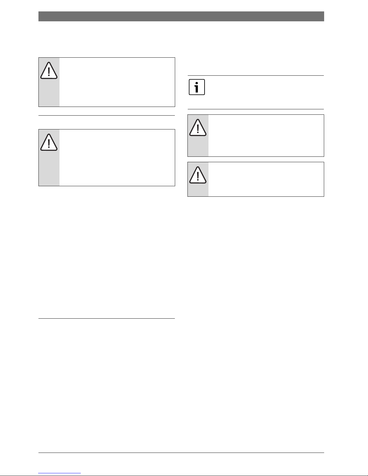
Warnings are indicated in the text by a
warning triangle and a gray background.
In case of danger due to electric shock, the
exclamation point on the warning triangle is
replaced with a lightning symbol.
Important information that presents no risk
to people or property is indicated with this
symbol. It is separated by horizontal lines
above and below the text.
Symbol Meaning
B Sequence of steps
→
Cross-reference to other points in this
document or to other documents
• Listing/list entry
– Listing/list entry (2nd level)
Table 1
4 | Information about the heater US
6 720 647 005 (2011/09)
2 Information about the heater
2.1 Disclaimer
2.1.1
Approval number
Commonwealth of Massachusetts
As a condition of installing this product in the
Commonwealth of Massachusetts a pressure relief valve
shall be installed on the cold water side, by a licensed
plumber MGL 142 Section 19.
(Approval number: P1-09-25).
2.2 Technical identification code
US Electronic Instantaneous
3 Maximum output (kW)
M Mechanical temperature control
W Wall hung
I Indoor
H Horizontal installation
B Water connections
2.3 Package contents
• Electric water heater
• 4 No. 8 wood screws
2.4 Model name and number
identification
US 3 - 1 M W I H B
US 6 - 1 M W I H B
US 7 - 1 M W I H B
US 9 - 1 M W I H B
Table 2
Model Name Model Number
Tronic 3000C Pro US 3-1 Pro
M W I H B
Tronic 3000C Pro US 6-1 Pro
M W I H B
Tronic 3000C Pro
US 7-1 Pro
M W I H B
Tronic 3000C Pro US 9-1 Pro
M W I H B
Table 3
Information about the heater | 5US
6 720 647 005 (2011/09)
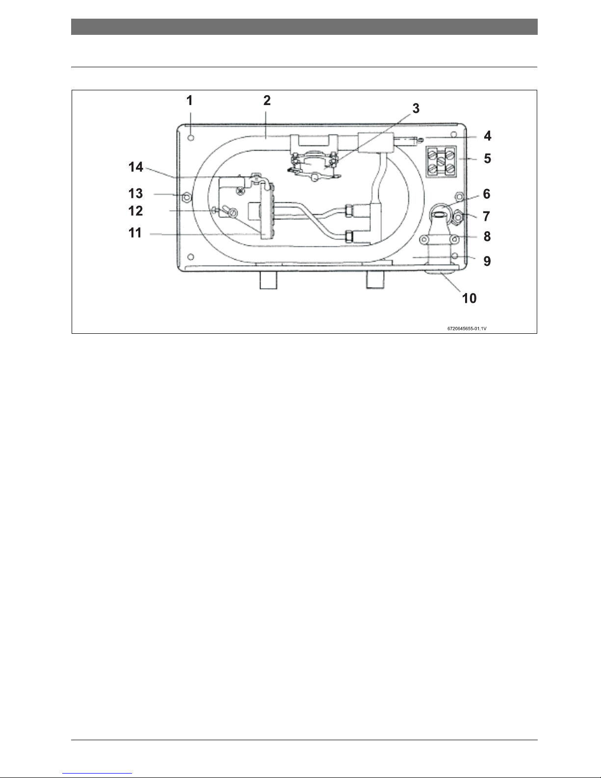
2.5 General description
Fig. 1
1 Mounting hole
2 Heat exchanger tube
3 Thermal cut-out (manual re-set)
4 Heating elements
5 Terminal block
6 Cable rear entry
7 Ground stud
8 Cable clamp
9 Filter and water pipe mounting
10 Cable side entry
11 Flow switch
12 Power selector
13 Cover fixing screw
14 Neon light
Outlet
Inlet
6 | Information about the heater US
6 720 647 005 (2011/09)
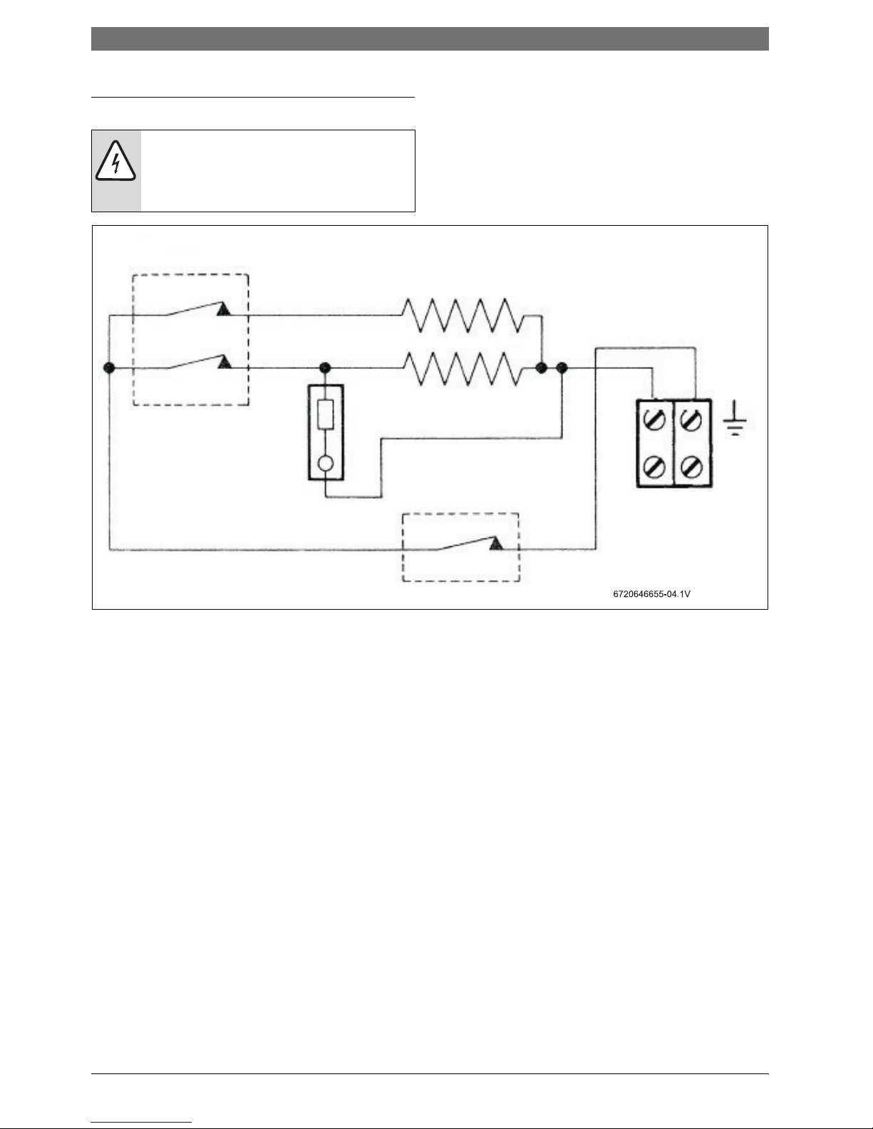
2.6 Electrical diagram
Fig. 2 Internal wiring plan
DANGER: Risk of electric shock!
B Always switch off the electrical supply to
the unit before removing cover or
performing any maintenance and service.
Heating elements
Electrical
supply
Manual reset Thermal cut-out
Neon
Power selector
and Flow switch
Information about the heater | 7US
6 720 647 005 (2011/09)
2.7 Function
How the water heater works:
• Water comes in through the cold water inlet.
• The flow switch senses how much water is passing
through the unit. If it detects more than the preset
level, the unit’s heating elements switch on. This is
shown by the neon light glowing.
• The water is heated instantly as it passes through the
copper heat exchanger tube.
The temperature of the water coming out of the unit
depends on:
• The voltage of the electrical supply,
• The temperature of the incoming water supply,
• The setting of the power selector,
• The flow rate,
• The power rating of the unit.
• Depending on the region of the country, the
temperature of the water supply can vary between
40 °F in winter to 70 °F in summer, with an average of
50 °F.
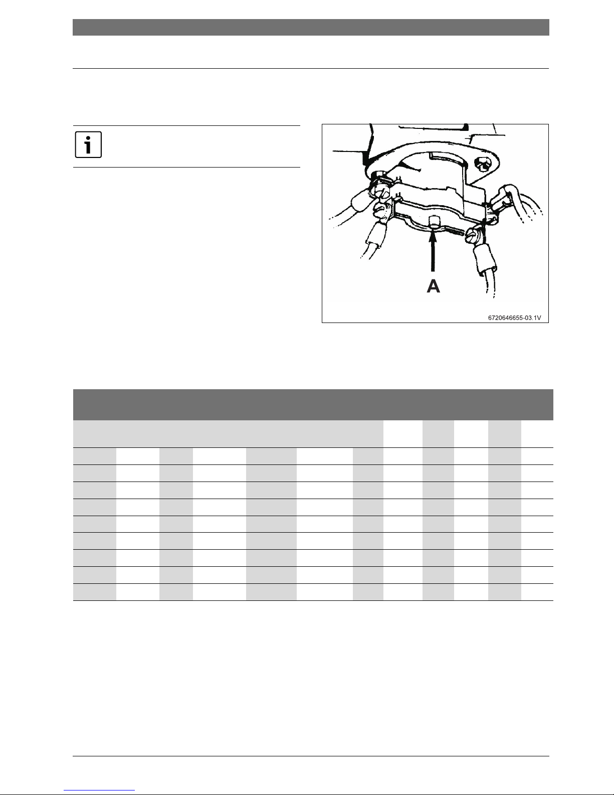
Fig. 3
A Manual reset thermal cut out
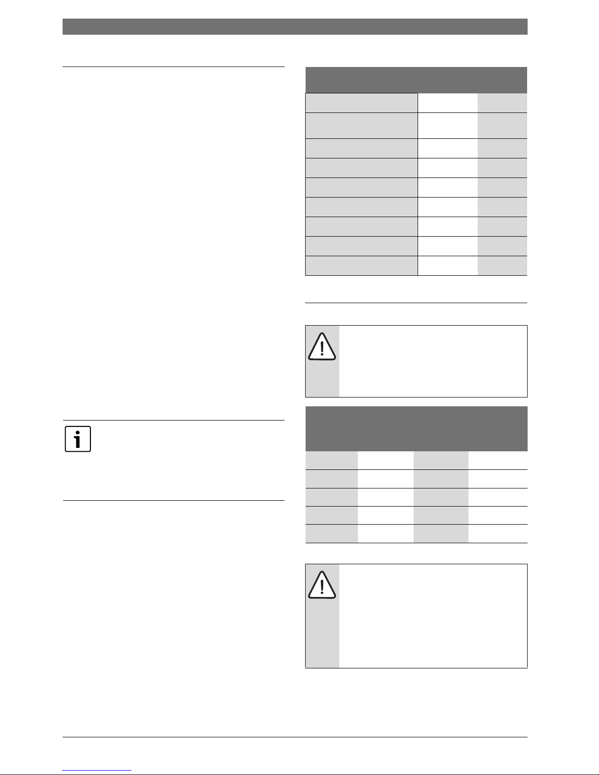
The table below shows the rise in water temperature you
can expect from the unit:
Manual reset thermal cut-out
The unit has a thermal cut-out (Fig. 1) which is mounted
on the heat exchanger tube. This will switch off the
heater elements if the water temperature goes above
194 °F.
If the cut-out trips it will need to be reset manually inside
the unit. This cut-out will only operate in exceptional
circumstances (Fig. 3). Call your service person or Bosch
Water Heating if this happens frequently.
The heater is designed for cold water supply
only. Do not supply with pre-heated water.
Model Volts Amps
Element
Resistance
High
Setting Low Setting Temperature Rise (deg F) at Flow Rate (GPM)
0,5
GPM
0,75
GPM
1,0
GPM
1,5
GPM
2,0
GPM
2,5
GPM
US9 240 40 2x12 Ω 9,5kW - NA 84F 64F 42F 32F NA
US9 240 20 1x12 Ω - 4,75kW NA 42F 32F 21F 16F NA
US9 208 35 2x12 Ω 7,1kW - NA 64F 48F 32F 24F NA
US9 208 18 1x12 Ω - 3,5kW NA 32F 24F 16F 12F NA
US6 277 22 2x25 Ω 6,0kW - 81F 55F 42F 27F NA NA
US6 277 11 1x25 Ω - 3,0kW 41F 28F 21F 14F NA NA
US3 120-110 27 2x8 Ω 3,4-3,0kW - 41F 28F 20F NA NA NA
US7 240-220 30 2x16 Ω 7,2-6,1kW - NA 63F 48F 32F 24F NA
US7 240-220 15 1x16 Ω - 3,6- 3,05kW NA 32F 24F 16F 12F NA
Table 4
8 | Regulations US
6 720 647 005 (2011/09)
3 Regulations
Any local by-laws and regulations pertaining to
installation and use of electric water heater appliances
must be observed. Please refer to the laws that should
be attended in your country.
• The electrical installation must conform to current
National Electrical Codes.
• To reduce the risk of electrical shock, connect this
terminal or connector to the grounding terminal of the
electrical service of supply panel with a continuous
copper wire in accordance with the Canadian
Electrical Code, Part I.
• This product shall be protected by a Class A ground
fault circuit interrupter.
• In the Commonwealth of Massachusetts a licensed
plumber or electrician must perform the installation.
(Approval number: P1-09-25).
• In the Commonwealth of Massachusetts a pressure
relief valve shall be installed on the cold water side by
a licensed plumber. (MGL 142 Section 19, Approval
number P1-09-25).
• The unit must be wired by a qualified electrician, in
accordance with the current version of the National
Electrical Code US) or Canadian Electric Code
(Canada).
• When the heater is not within sight of the electrical
circuit breakers, a circuit breaker lockout or
additional local means of disconnection for all nongrounded conductors must be provided that is within
sight of the appliance. (Ref NEC 422.31.).
• The power cable size and the installation must be in
accordance with the Canadian Electrical Code,
C22.1-02.
WARNING:
California Proposition 65 lists chemical
substances known to the state to cause
cancer, birth defects, death, serious illness
or other reproductive harm. This product
may contain such substances, be their
origin from fuel combustion (gas, oil) or
components of the product itself.
Installation | 9US
6 720 647 005 (2011/09)
4 Installation
4.1 Important information
Please follow these instructions. Failure to follow
instructions may result in:
• Damage or injury.
• Improper installation/operation.
• Loss of warranty.
4.1.1 Freeze prevention
Introduction
Please note that the installation manual states that the
water heater must not be installed in a location where it
may be exposed to freezing temperatures. If the heater
must be left in a space that is likely to experience
freezing temperatures, all water must be drained from
the heater.
Freeze damage is not covered under the warranty.
Draining the heater
Due to the shape of the heat exchangers and connecting
pipe, it is extremely difficult to get all of the water out of
the heater. Follow the procedure below to best minimize
the chance of freezing:
B Disconnect electric supply.
B Disconnect cold and hot water pipes from fittings on
bottom of heater. Allow water to drain out (have a
catch basin ready).
B After allowing all water to drain out, the heater should
be blown out with low pressure compressed air to
remove as much water as possible from water heater
modules. Bursts of air work better than continuous
flow.
Remember, these suggestions are only made to help
minimize the potential for freeze damage and are not to
be construed as the guaranteed method for dealing with
freeze possibilities.
4.2 Installing the Tronic 3000C Pro
To operate correctly the unit needs the following
running pressures:
Sink
• Min: 10 psi (0,7 bar)
• Max: 150 psi (10,3 bar)
DANGER: Risk of electric shock!
B For safety reasons, disconnect the power
supply to the heater before any service or
testing is performed.
WARNING:
B This heater must be electrically grounded
in accordance with the most recent
edition of the National Electrical Code.
NFPA 70. In Canada, all electrical wiring
to the heater must be in accordance with
local codes and the Canadian Electrical
Code, CSA C22.1 Part 1.
DANGER:
B The installation must only be performed
by a qualified person in accordance with
these instructions.
B Bosch Thermotechnology Corp. is not
responsible for improperly installed
appliances.
WARNING:
B The heater must only be wall mounted
and positioned with the water
connections located either at bottom or
the right side of the unit see Fig. 6. Under
no circumstances should the heater be
mounted differently.
WARNING:
B ELECTRICITY IS EXTREMELY
DANGEROUS. TAKE EXTRA
PRECAUTIONS AND ENSURE ALL
CIRCUIT BREAKERS ARE OFF BEFORE
PERFORMING ANY WORK TO THE
HEATER.
Use of agents like anti-freeze are not
allowed as they may cause damage to the
water heater’s internal components.
WARNING:
B Do not install the Tronic 3000C Pro in a
room where there is a chance of freezing.
NOTE:
B Read entire instructions.
B Check the pressure of the main water
supply.
10 | Installation US
6 720 647 005 (2011/09)
4.3 Water connections
B The unit should be connected directly to the main
cold water supply and not to pre- heated water. The
unit should be installed with service valves on both
the inlet and outlet. These valves can be used to turn
off the water supply to the unit if it needs servicing, or
to reduce the water flow if it is too high.
B We recommend that you use ½" copper or high
pressure flex connections.
B Use Teflon tape for sealing pipe threads. Do NOT use
pipe dope.
B Remember to keep the hot water pipe runs as short
as possible. In some cases it may be worth fitting a
second unit to serve an additional fixture.
B The inlet and outlet are clearly marked on the unit.
They each have a ½" NPT connector.
B If the unit is to supply a sink, we recommend that you
use aerators, which you can get from your local
distributor/dealer.
B If the unit is to supply more than one sink, the aerator
should be the same at each tap if they are to be used
at the same time. If not, one outlet will take all the
water.
B After the unit has been plumbed in, and before you
wire it, flush it with water to remove any debris or
loose particles. Failure to do so may make the unit
inoperable.
4.3.1 Water quality
Water quality can have an impact on appliance longevity
and may not be covered under the manufacturer's
warranty.
B For water analysis data call your local water
department, or if on a well, have well water analyzed
periodically.
If water quality exceeds one or more of the values
specified below, Bosch recommends consulting a
local water treatment professional for water
softening/conditioning options.
4.4 Electrical connections
As a condition of installing this product in
the Commonwealth of Massachusetts a
pressure relief valve must be installed on
the cold water side by a licensed plumber.
MGL 42 Section 19.
Approval number: P1-09-25
Description
Max. Levels
pH pH 6.5 - 8.5
TDS (total Dissolved
Solids)
mg/l or ppm 500
Total hardness mg/l or ppm
100
Aluminum mg/l or ppm 2.0
Chlorides mg/l or ppm 250
Copper mg/l or ppm 1.0
Iron mg/l or ppm 0.3
Manganese mg/l or ppm 0.05
Zinc mg/l or ppm 5.0
Table 5
WARNING:
B The unit must be installed by a qualified
electrician.
B The unit must be grounded.
B Connect the unit to power.
Model
Rated
Voltage
(V)
Rated
Current
(A)
Recommen
d Wire Size
(AWG)
US3 110 30 10
US6 277 25 10
US7 240 30 10
US9 208 35 8
US9 240 40 8
Table 6
NOTE:
When the Tronic 3000C Pro is not within
sight of the electrical circuit breakers, a
circuit breaker lockout or additional local
means of disconnection for all non
grounded conductors must be provided that
is within sight of the appliance. (REF NEC
422.31)
Installation | 11US
6 720 647 005 (2011/09)
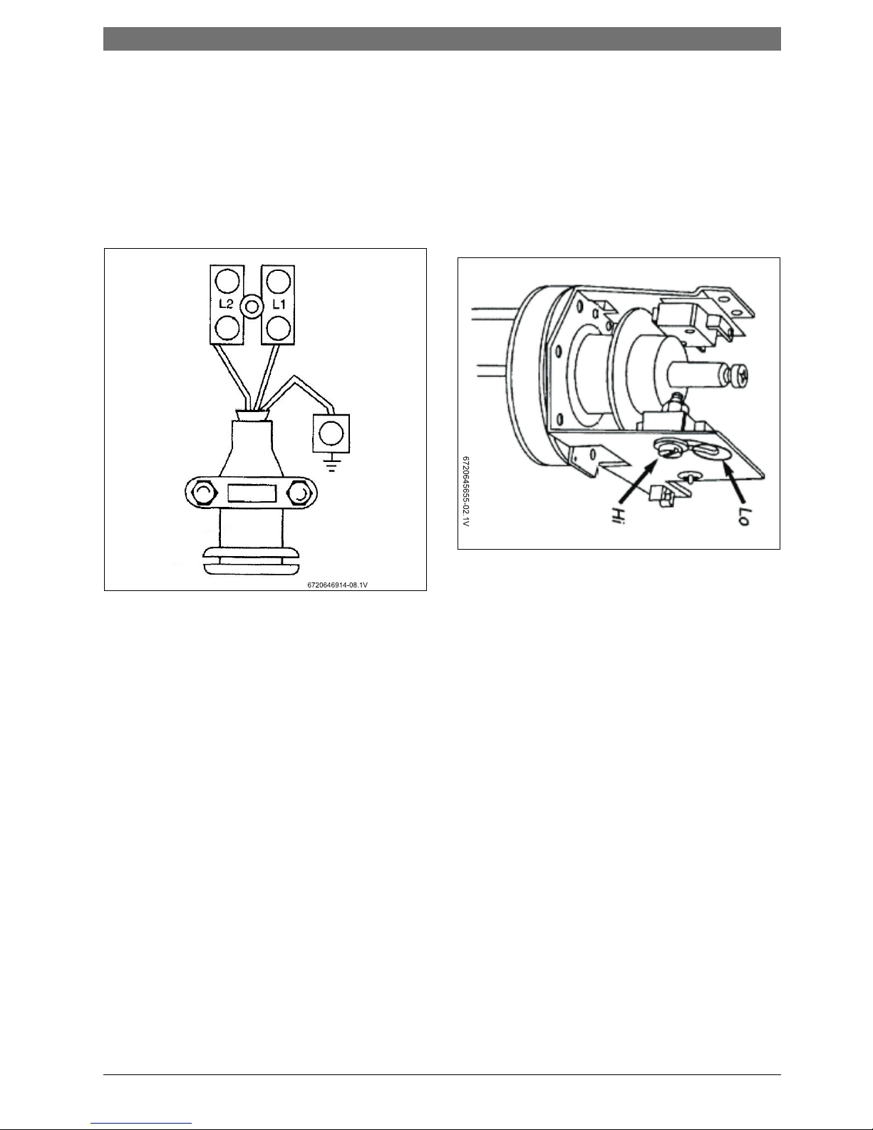
Connecting the unit to power
B Strip back the insulation on the power wires about
3/8". Any insulation on the ground should be stripped
back about 3/4".
B Feed the cable through the cover bottom or backplate
rear entry grommets, as appropriate.
B Connect the cables to the terminal block and ground
stud (Fig. 4):
Fig. 4 Cable termination
B Make sure that all the terminal block screws are
tightened securely. Loose connections can cause
wires to heat up.
B Make sure that the ground wire is wrapped around its
terminal stud and into the saddle washer. The nut
should be tightened securely.
B Set the Power Selector Screw (Fig. 5) on the desired
setting. If it is set to LO, only one heating element will
operate and the output will be half power. See the
Table 4 on page 7 for temperature rise at various flow
rates. If the element is set on HI, both heating
elements will operate and the output will be full
power. When setting the Power Selector Screw, it is
important that the screw be adjusted all the way to
the end of the slot and that it be well tightened.
Fig. 5 Power selector screw
B Attach the front cover and tighten the retaining
screws.
Rubber
Sleeve
Ground
12 | Installation US
6 720 647 005 (2011/09)
4.5 Securing the unit to the wall
4.5.1 Deciding the position
B If being used in a public place, position the unit out of
reach to discourage vandalism.
B Mount the unit onto a flat section of wall, well away
from any potential splashes of water or spray.
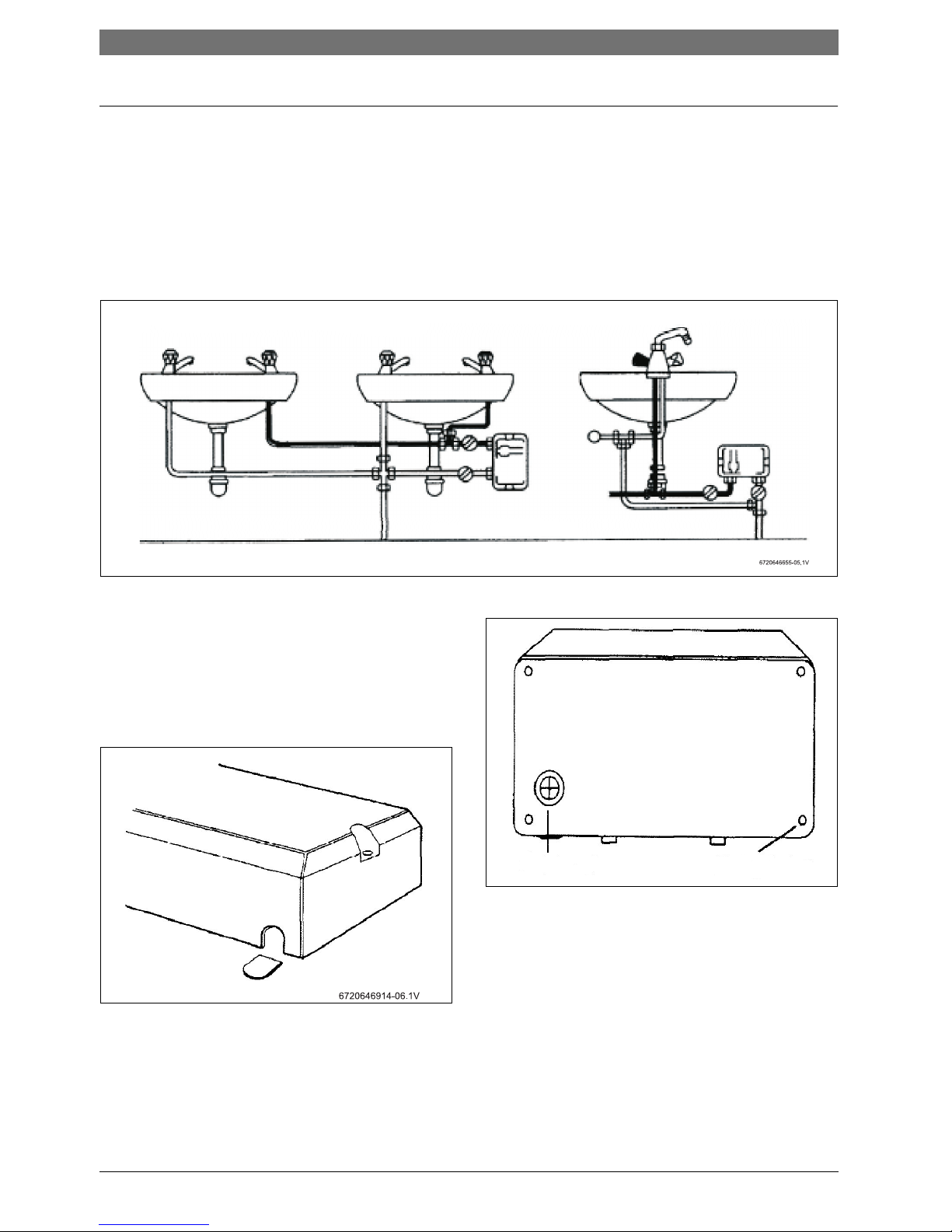
B Mount only as shown in Fig. 6 with the water
connections located either at bottom or the right side
of the unit.
Remember to keep the lengths of hot water pipe to a
minimum in order to save energy.
B If the unit is to supply a sink, you can fit it either above
or below the sink.
Fig. 6 Examples of installations
4.5.2 Deciding the wiring route
You have a choice of whether to feed the electric cable
through the cover bottom or through the back of the
unit,
B If it is going to be through the cover bottom, cut out
the plastic lug to expose the rubber sleeve (Fig. 7):
Fig. 7 Cover lug cut out
B If it is going through the back of the unit, cut through
the grommet on the backplate with a sharp knife.
Make sure that you do not remove the grommet from
the backplate (Fig. 8):
Fig. 8 Back of unit
1 Grommet
2 Fixing holes
B Feed the cable through the grommet before you
mount the unit to the wall. If you are using an
approved cable fitting, remove the grommet.
4.5.3 Mounting on the wall
B Undo the retaining screws on the cover and take the
cover of the unit. Hold the backdate in position
against the wall while you mark the four mounting
holes.
Cold
Hot
Hot
Front view
Hot
Cold
Cold
1
2
6720646914-07.1V
Installation | 13US
6 720 647 005 (2011/09)
B Drill the holes and secure the unit to the wall using
the four no. 8 wood screws supplied.
WARNING:
B Do not install a non-return check valve
within 6 feet of the inlet.
14 | Starting up the Tronic 3000C Pro US
6 720 647 005 (2011/09)
5 Starting up the Tronic 3000C Pro
5.1 Sink
B Check that the power is switched on at the circuit
breaker panel.
B Turn on the hot tap FULLY.
If you do not turn the tap full on, you will find that the
temperature of the water may vary. The hot water
temperature can then be set by adjusting the flow.
If the unit has been used recently:
B run the water through for a few seconds to let the
temperature settle down.
If the unit has been used recently, You may initially get
a short burst of very hot water from the unit.
If a second tap connected to the unit is also turned on,
the hot water will be shared between the two, therefore
the flow and/or the temperature of the water will
decrease.
5.2 Adjusting the flow
Checking for leaks
B Ensure the service valves are open and check that no
pipe joints leak.
B Turn on the hot tap fully at the sink.
B Adjust the outlet service valve until the water comes
out of the tap at the required temperature, (increase
flow for cooler, decrease for hotter). Refer to Table 4,
page 7 for expected temperature rise at given flow
rates.
B Check that the unit works correctly when the sink tap
is closed and then opened again; if not adjust the
service valve slightly.
B The inlet service valve should not be used to regulate
temperature.
WARNING:
B Do not use the unit if you think it may be
frozen, as this could result in serious
damage to the unit. Wait until you are
sure it has completely thawed out before
you switch it on.
WARNING:
Before turning on power:
B Open cold water shutoff valve to the unit
and turn on all hot water taps supplied by
the unit. Flow water out the tap(s) until
all air has purged from the unit and
plumbing.
When using the hot water at a fixture, open
tap fully. To regulate hot water temperature,
adjust water flow accordingly as directed in
Section 5.2.
NOTE:
If the unit is servicing a single lever faucet
you may need to restrict the cold water
supply to the faucet to balance water
pressure and improve performance.
NOTE:
B Before leaving the site, the installer
should demonstrate the unit to the user
and give him/her this guide.
Troubleshooting | 15US
6 720 647 005 (2011/09)
6 Troubleshooting
If the problem persists:
The person who initially installed the unit is probably the best one to contact for help. You can also call Bosch
Thermotechnology Corporation at 800-798-8161 or visit www.bosch-climate.us. Please have this guide with you when
you call.
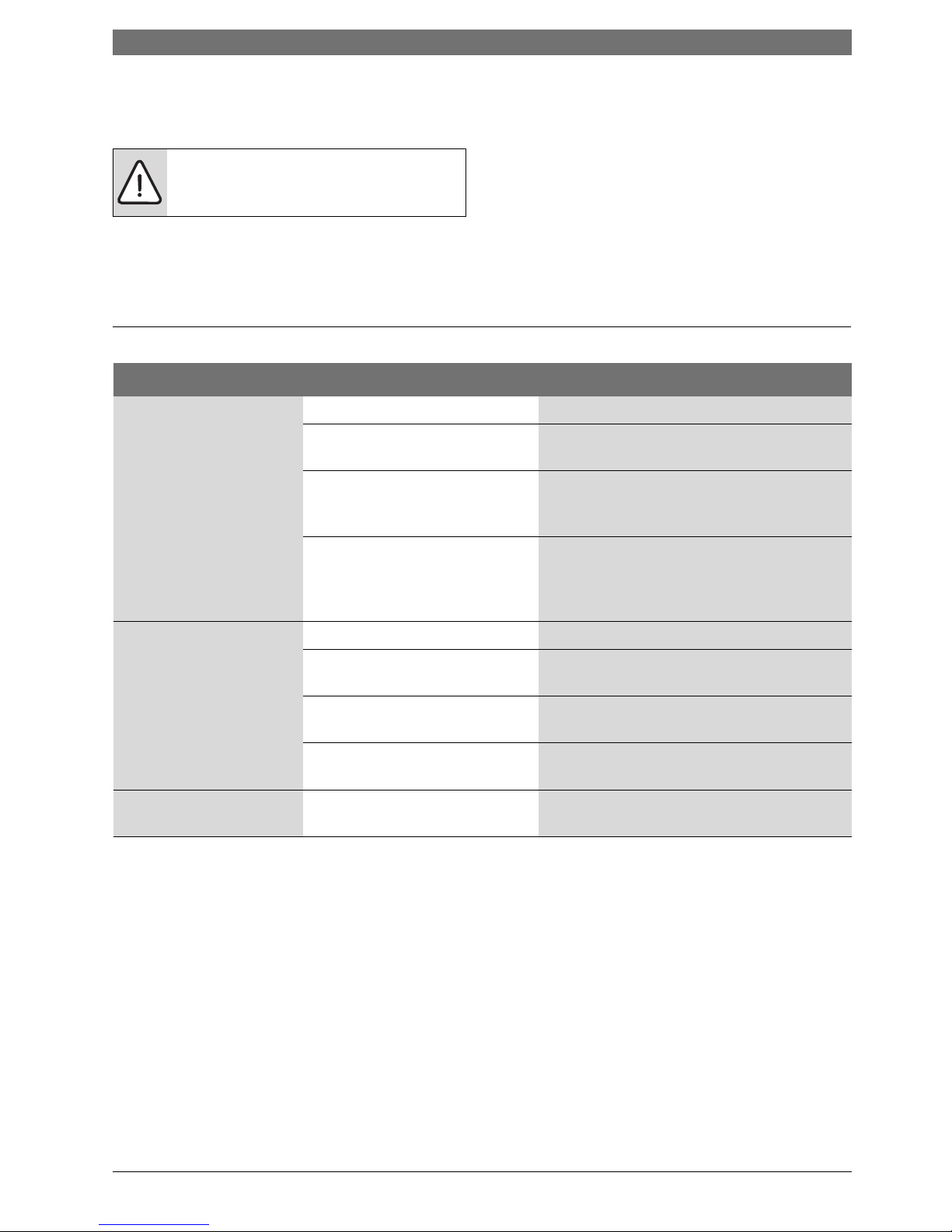
6.1 For the Installer
WARNING: Always switch off the electricity
supply to the unit before you remove the
cover.
Symptom Cause What do do
Cold water only -neon light
off.
Electricity not on. Check electrical supply.
The water supply is connected to
the OUTLET of the unit.
Reconnect the water supply to the INLET
(marked in blue).
The high temperature thermal cut
out has tripped.
Reset it by opening the unit and pushing the
button on the cut out (Fig. 3). Before you do
this you must find the cause of the problem.
The flow switch is not working. Turn off the power and observe if the flow
switch activates when the water is turned on.
If not contact Bosch Thermotechnology 800798-8161 www.bosch-climate.us
Water too cold -neon light
on.
Water flow too high. Adjust water flow (see Table 4).
The power selector screw not all
the way to “HI”.
Change the power select screw to “HI”, see
Fig. 5.
One element is not working. Switch off the electricity and check the
resistance of the elements (see Table 4).
The power supply voltage has
dropped.
Check the supply voltage to the heater (see
Table 4).
Water flow too low, or
temperature too high.
There are restrictions in the
plumbing.
Check the plumbing. Only use Teflon tape for
sealing pipe joints.
Table 7
 Loading...