


 Loading...
Bosch UPH-C630N-L8585, UPH-C630N-L86154, UPH-C610N-L8120, UPH-C630N-L8120, UPH-C498N-L8585 Operation Manual
...High-Speed Positioning System (HSPS)
UPH Series

en Operation Manual

High-Speed Positioning System |
Table of Contents | en |
3 |
|
(HSPS) |
|||
|
|
||
|
|
|
Table of contents
1 |
Safety |
5 |
1.1 |
About this Manual |
5 |
1.2 |
Legal Information |
5 |
1.3 |
Safety precautions |
5 |
1.4 |
Important safety instructions |
5 |
1.5 |
Important Notices |
7 |
1.6 |
Customer Support and Service |
11 |
2 |
Unpacking |
12 |
2.1 |
Parts List |
12 |
2.2 |
Tools Required |
12 |
2.3 |
Safety Rules |
12 |
3 |
|
|
Description |
14 |
|
4 |
Installing the Camera/Lens |
15 |
4.1 |
Installing the Camera/Lens Mounting Tray |
15 |
4.2 |
Preparing the Camera |
17 |
4.3 |
Connecting the Camera and Motorized Lens |
18 |
5 |
|
|
Installing the High Speed Positioning System |
20 |
|
5.1 |
Mounting the High Speed Positioning System |
20 |
5.2 |
Wiring the Device |
24 |
5.3 |
Wiring the Video Cable |
25 |
5.4 |
Connecting the Power Supply |
26 |
6 |
|
|
Connecting to the Standard Base |
30 |
|
7 |
|
|
Connecting to the IR360 Base |
31 |
|
8 |
Fixing the Top Unit |
32 |
9 |
Assembling and Connecting IR360 Models (optional) |
34 |
9.1 |
Fitting the Bracket |
34 |
9.2 |
Assembling the Spotlights |
34 |
9.3 |
Fitting the Spotlights on the Bracket |
35 |
9.4 |
Connecting the Spotlights |
36 |
10 |
|
|
Making Connections for the Pump of the Washer Kit (Optional) |
41 |
|
11 |
Configuring the Device |
42 |
11.1 |
Pelco D Baud Rate |
43 |
11.2 |
Protocol |
43 |
11.3 |
Setting the Address |
43 |
11.4 |
RS485 Line Termination |
44 |
11.5 |
Biphase/Bilinx Termination |
44 |
11.6 |
Connections |
45 |
12 |
|
|
Configuring the System |
48 |
|
12.1 |
Language Menu |
48 |
12.2 |
Display Setup Menu |
48 |
12.2.1 |
Area Parameters Menu |
49 |
12.2.2 |
Changing the Edit Text Menu |
51 |
12.2.3 |
Display Parameters |
52 |
12.3 |
Motion Parameters Menu |
53 |
12.3.1 |
Speed Menu |
53 |
12.3.2 |
Limits |
55 |
12.3.3 |
Preset/Patrol/Autopan |
56 |
Bosch Security Systems, Inc. |
Operation Manual |
2013.11 | 5.2 | F.01U.291.981 |

4 |
en | Table of Contents |
High-Speed Positioning System |
||
(HSPS) |
||||
|
|
|
||
|
|
|
||
12.3.4 |
Wiper-Washer |
62 |
||
12.3.5 |
Alarms |
63 |
||
12.4 |
|
Camera/Infrared Parameters |
64 |
|
12.4.1 |
Lens Modules Parameters and Area Masking |
64 |
||
12.4.2 |
Infrared Parameters |
66 |
||
12.4.3 |
Illuminator/Dinion Configuration |
66 |
||
12.5 |
|
Load Default Configuration |
67 |
|
12.6 |
|
Setup Info Menu |
68 |
|
13 |
|
|
|
|
|
Keyboard Commands List - Bosch |
69 |
||
13.1 |
|
Keyboard Commands List - Pelco |
69 |
|
13.2 |
|
Changing the Settings |
70 |
|
13.3 |
|
Changing the Numeric Fields |
70 |
|
14 |
|
|
|
|
|
On-screen Display (OSD) |
71 |
||
15 |
|
|
|
|
|
Troubleshooting |
73 |
||
15.1 |
|
Low and High Temperatures |
74 |
|
15.2 |
|
Dimensions and Range of Movement |
75 |
|
16 |
|
|
|
|
|
Maintenance |
77 |
||
16.1 |
|
Cleaning |
77 |
|
16.2 |
|
Replacing the Fuses |
77 |
|
17 |
|
|
|
|
|
Appendix A: Wiring Summary |
78 |
||
2013.11 | 5.2 | F.01U.291.981 |
Operation Manual |
Bosch Security Systems, Inc. |

High-Speed Positioning System |
Safety | en |
5 |
|
(HSPS) |
|||
|
|
||
|
|
|
1 |
Safety |
1.1 |
About this Manual |
|
This manual has been compiled with great care and the information it contains has been |
|
thoroughly verified. The text was complete and correct at the time of printing. Because of the |
|
ongoing development of products, the content of the manual may change without notice. |
|
Bosch Security Systems accepts no liability for damage resulting directly or indirectly from |
|
faults, incompleteness, or discrepancies between the manual and the product described. |
1.2 |
Legal Information |
|
Copyright |
|
This manual is the intellectual property of Bosch Security Systems, Inc. and is protected by |
|
copyright. All rights reserved. |
|
Trademarks |
|
All hardware and software product names used in this document are likely to be registered |
|
trademarks and must be treated accordingly. |
1.3 |
Safety precautions |
Danger!
High risk: This symbol indicates an imminently hazardous situation such as “Dangerous Voltage” inside the product. If not avoided, this will result in an electrical shock, serious bodily injury, or death.
Warning!
!Medium risk: Indicates a potentially hazardous situation. If not avoided, this may result in minor or moderate injury.
Caution!
!Low risk: Indicates a potentially hazardous situation. If not avoided, this may result in property damage or risk of damage to the unit.
Notice!
This symbol indicates information or a company policy that relates directly or indirectly to the safety of personnel or protection of property.
1.4 |
Important safety instructions |
|
|
Read, follow, and retain all of the following safety instructions. Heed all warnings on the unit |
|
|
and in the operating instructions before operation. |
|
|
1. |
Cleaning - Unplug the unit from the outlet before cleaning. Follow any instructions |
|
|
provided with the unit. Generally, using a dry cloth for cleaning is sufficient but a moist, |
|
|
fluff-free cloth or leather shammy may also be used. Do not use liquid cleaners or aerosol |
|
|
cleaners. |
|
2. |
Heat Sources - Do not install the unit near any heat sources such as radiators, heaters, |
|
|
stoves, or other equipment (including amplifiers) that produce heat. |
Bosch Security Systems, Inc. |
Operation Manual |
2013.11 | 5.2 | F.01U.291.981 |

6 |
en | Safety |
High-Speed Positioning System |
|
(HSPS) |
|||
|
|
||
|
|
|
3.Ventilation - Any openings in the unit enclosure are provided for ventilation to prevent overheating and ensure reliable operation. Do not block or cover these openings. Do not place the unit in an enclosure unless proper ventilation is provided, or the manufacturer's instructions have been adhered to.
4.Object and liquid entry - Never push objects of any kind into this unit through openings as they may touch dangerous voltage points or short-out parts that could result in a fire or electrical shock. Never spill liquid of any kind on the unit. Do not place objects filled with liquids, such as vases or cups, on the unit.
5.Controls adjustment - Adjust only those controls specified in the operating instructions. Improper adjustment of other controls may cause damage to the unit. Use of controls or adjustments, or performance of procedures other than those specified, may result in hazardous radiation exposure.
6.Overloading - Do not overload outlets and extension cords. This can cause fire or electrical shock.
7.Power sources - Operate the unit only from the type of power source indicated on the label. Before proceeding, be sure to disconnect the power from the cable to be installed into the unit.
–For battery powered units, refer to the operating instructions.
–For external power supplied units, use only the recommended or approved power supplies.
–For limited power source units, this power source must comply with EN60950. Substitutions may damage the unit or cause fire or shock.
–For 24 VAC units, voltage applied to the unit's power input should not exceed ±10%, or 28 VAC. User-supplied wiring must comply with local electrical codes (Class 2 power levels). Do not ground the supply at the terminals or at the unit's power supply terminals.
–If unsure of the type of power supply to use, contact your dealer or local power company.
Notice!
Installation category (also called Overvoltage Category) specifies the level of mains voltage surges that the equipment will be subjected to. The category depends upon the location of the equipment, and on any external surge protection provided. Equipment in an industrial environment, directly connected to major feeders/short branch circuits, is subjected to Installation Category III. If this is the case, a reduction to Installation Category II is required. This can be achieved by use of an isolating transformer with an earthed screen between primary and secondary, or by fitting listed Surge Protective Devices (SPDs) from live to neutral and from neutral to earth. Listed SPDs shall be designed for repeated limiting of transient voltage surges, suitable rated for operating voltage and designated as follows:
-Type 2 (Permanently connected SPDs intended for installation on the load side of the service equipment overcurrent device)
-Nominal Discharge Current (In) 20 kA min.
For example: FERRAZ SHAWMUT, STT2240SPG-CN, STT2BL240SPG-CN rated 120/240 VAC, (In=20 kA)
8.Servicing - Do not attempt to service this unit yourself. Opening or removing covers may expose you to dangerous voltage or other hazards. Refer all servicing to qualified service personnel.
2013.11 | 5.2 | F.01U.291.981 |
Operation Manual |
Bosch Security Systems, Inc. |

High-Speed Positioning System |
Safety | en |
7 |
||
(HSPS) |
|
|
||
|
|
|
|
|
|
|
|
|
|
|
9. |
Damage requiring service - Unplug the unit from the main AC power source and refer |
|
|
|
|
servicing to qualified service personnel when any damage to the equipment has occurred, |
||
|
|
such as: |
|
|
|
|
– the power supply cord or plug is damaged; |
|
|
|
|
– exposure to moisture, water, and/or inclement weather (rain, snow, etc.); |
|
|
|
|
– liquid has been spilled in or on the equipment; |
|
|
|
|
– an object has fallen into the unit; |
|
|
|
|
– unit has been dropped or the unit cabinet is damaged; |
|
|
|
|
– unit exhibits a distinct change in performance; |
|
|
|
|
– unit does not operate normally when the user correctly follows the operating |
|
|
|
|
instructions. |
|
|
|
10. |
Replacement parts - Be sure the service technician uses replacement parts specified by |
|
|
|
|
the manufacturer, or that have the same characteristics as the original parts. |
|
|
|
|
Unauthorized substitutions may cause fire, electrical shock, or other hazards. |
|
|
|
11. |
Safety check - Safety checks should be performed upon completion of service or repairs |
||
|
|
to the unit to ensure proper operating condition. |
|
|
|
12. |
Installation - Install in accordance with the manufacturer's instructions and in accordance |
||
|
|
with applicable local codes. |
|
|
|
|
|
|
|
|
Notice! |
|
|
|
|
This product must only be used with a UR marked camera, rated 6-12 VDC with a maximum |
|
||
|
power consumption of 5 W and a flammability class V-0 and Product Category NWGQ2,8. |
|
||
|
|
|
||
|
13. |
Attachments, changes or modifications - Only use attachments/accessories specified by |
||
|
|
the manufacturer. Any change or modification of the equipment, not expressly approved |
|
|
|
|
by Bosch, could void the warranty or, in the case of an authorization agreement, authority |
||
|
|
to operate the equipment. |
|
|
1.5 |
Important Notices |
|
|
|
|
Disclaimer |
|
|
|
|
Underwriter Laboratories Inc. (“UL”) has not tested the performance or reliability of the |
|
||
security or signaling aspects of this product. UL has only tested fire, shock and/or casualty hazards as outlined in UL's Standard(s) for Safety for Closed Circuit Television Equipment, UL 2044. UL Certification does not cover the performance or reliability of the security or signaling aspects of this product.
UL MAKES NO REPRESENTATIONS, WARRANTIES, OR CERTIFICATIONS WHATSOEVER REGARDING THE PERFORMANCE OR RELIABILITY OF ANY SECURITY OR SIGNALING RELATED FUNCTIONS OF THIS PRODUCT.
FCC & ICES Information
(U.S.A. and Canadian Models Only)
This device complies with part 15 of the FCC Rules. Operation is subject to the following conditions:
–this device may not cause harmful interference, and
–this device must accept any interference received, including interference that may cause undesired operation.
NOTE: This equipment has been tested and found to comply with the limits for a Class A digital device, pursuant to Part 15 of the FCC Rules and ICES-003 of Industry Canada. These limits are designed to provide reasonable protection against harmful interference when the equipment is operated in a commercial environment. This equipment generates, uses, and radiates radio frequency energy and, if not installed and used in accordance with the
Bosch Security Systems, Inc. |
Operation Manual |
2013.11 | 5.2 | F.01U.291.981 |
8 |
en | Safety |
High-Speed Positioning System |
|
(HSPS) |
|||
|
|
||
|
|
|
instruction manual, may cause harmful interference to radio communications. Operation of this equipment in a residential area is likely to cause harmful interference, in which case the user will be required to correct the interference at his expense.
Intentional or unintentional modifications, not expressly approved by the party responsible for compliance, shall not be made. Any such modifications could void the user's authority to operate the equipment. If necessary, the user should consult the dealer or an experienced radio/television technician for corrective action.
The user may find the following booklet, prepared by the Federal Communications Commission, helpful: How to Identify and Resolve Radio-TV Interference Problems. This booklet is available from the U.S. Government Printing Office, Washington, DC 20402, Stock No. 004-000-00345-4.
Informations FCC et ICES
(modèles utilisés aux États-Unis et au Canada uniquement)
Ce produit est conforme aux normes FCC partie 15. la mise en service est soumises aux deux conditions suivantes :
–cet appareil ne peut pas provoquer d'interférence nuisible et
–cet appareil doit pouvoir tolérer toutes les interférences auxquelles il est soumit, y compris les interférences qui pourraient influer sur son bon fonctionnement.
AVERTISSEMENT: Suite à différents tests, cet appareil s’est révélé conforme aux exigences imposées aux appareils numériques de Classe A en vertu de la section 15 du règlement de la Commission fédérale des communications des États-Unis (FCC). Ces contraintes sont destinées à fournir une protection raisonnable contre les interférences nuisibles quand l'appareil est utilisé dans une installation commerciale. Cette appareil génère, utilise et émet de l'energie de fréquence radio, et peut, en cas d'installation ou d'utilisation non conforme aux instructions, générer des interférences nuisibles aux communications radio. L’utilisation de ce produit dans une zone résidentielle peut provoquer des interférences nuisibles. Le cas échéant, l’utilisateur devra remédier à ces interférences à ses propres frais.
Au besoin, l’utilisateur consultera son revendeur ou un technicien qualifié en radio/télévision, qui procédera à une opération corrective. La brochure suivante, publiée par la Commission fédérale des communications (FCC), peut s’avérer utile : How to Identify and Resolve Radio-TV Interference Problems (Comment identifier et résoudre les problèmes d’interférences de radio et de télévision). Cette brochure est disponible auprès du U.S. Government Printing Office, Washington, DC 20402, États-Unis, sous la référence n° 004-000-00345-4.
Notice!
This is a class A product. In a domestic environment this product may cause radio interference, in which case the user may be required to take adequate measures.
Accessories - Do not place this unit on an unstable stand, tripod, bracket, or mount. The unit may fall, causing serious injury and/or serious damage to the unit. Use only with the cart, stand, tripod, bracket, or table specified by the manufacturer. When a cart is used, use caution and care when moving the cart/apparatus combination to avoid injury from tip-over. Quick stops, excessive force, or uneven surfaces may cause the cart/unit combination to overturn. Mount the unit per the manufacturer's instructions.
2013.11 | 5.2 | F.01U.291.981 |
Operation Manual |
Bosch Security Systems, Inc. |

High-Speed Positioning System |
Safety | en |
9 |
|
(HSPS) |
|||
|
|
||
|
|
|
Disposal
Your Bosch product has been developed and manufactured using highquality materials and components that can be reused.
This symbol means that electronic and electrical devices that have reached the end of their working life must be disposed of separately from household waste.
In the EU, separate collecting systems are already in place for used electrical and electronic products. Please dispose of these devices at your local communal waste collection point or at a recycling center.
All-pole power switch - Incorporate an all-pole listed circuit breaker, with a contact separation of at least 20A, 3 mm (400 V not essential) in each pole, into the electrical installation of the building.If it is needed to open the housing for servicing and/or other activities, use this allpole switch as the main disconnect device for switching off the voltage to the unit.
Warning!
For the standard models with 120/230 VAC power, an external junction box with a readily
!accessible 2-pole disconnect device must be incorporated.For the IR model UPH-H-WDIR-24, the 24 VAC power must be provided by a UL listed power supply with a double insulation transformer.
Camera grounding - For mounting the camera in potentially damp environments, ensure to ground the system using the ground connection of the power supply connector (see section: Connecting external power supply).
Camera lens - An assembled camera lens in the outdoor housing must comply and be tested in accordance with UL/IEC60950. Any output or signal lines from the camera must be SELV or Limited Power Source. For safety reasons the environmental specification of the camera lens assembly must be within the environmental specification of -10 °C (14 °F) to 50 °C (122 °F). Camera signal - Protect the cable with a primary protector if the camera signal is beyond 140 feet, in accordance with NEC800 (CEC Section 60).
Coax grounding:
–Ground the cable system if connecting an outside cable system to the unit.
–Connect outdoor equipment to the unit's inputs only after this unit has had its grounding plug connected to a grounded outlet or its ground terminal is properly connected to a ground source.
–Disconnect the unit's input connectors from outdoor equipment before disconnecting the grounding plug or grounding terminal.
–Follow proper safety precautions such as grounding for any outdoor device connected to this unit.
U.S.A. models only - Section 810 of the National Electrical Code, ANSI/NFPA No.70, provides information regarding proper grounding of the mount and supporting structure, grounding of the coax to a discharge unit, size of grounding conductors, location of discharge unit, connection to grounding electrodes, and requirements for the grounding electrode. Electronic Surveillance - This device is intended for use in public areas only. U.S. federal law strictly prohibits surreptitious recording of oral communications.
Environmental statement - Bosch has a strong commitment towards the environment. This unit has been designed to respect the environment as much as possible.
Bosch Security Systems, Inc. |
Operation Manual |
2013.11 | 5.2 | F.01U.291.981 |
10 en | Safety |
High-Speed Positioning System |
|
(HSPS) |
||
|
||
|
|
Electrostatic-sensitive device - Use proper CMOS/MOS-FET handling precautions to avoid electrostatic discharge. NOTE: Wear required grounded wrist straps and observe proper ESD safety precautions when handling the electrostatic-sensitive printed circuit boards.
Fuse rating - For protection of the device, the branch circuit protection must be secured with a maximum fuse rating as indicated in the manual. This must be in accordance with NEC800 (CEC Section 60).
Caution!
!For continued protection against risk of fire, replace, only with same type and rating of fuse.
Grounding and polarization - This unit may be equipped with a polarized alternating current line plug (a plug with one blade wider than the other blade). This safety feature allows the plug to fit into the power outlet in only one way. If unable to insert the plug fully into the outlet, contact a locally certified electrician to replace the obsolete outlet. Do not defeat the safety purpose of the polarized plug.
Alternately, this unit may be equipped with a 3-pole grounding plug (a plug with a third pin for earth grounding). This safety feature allows the plug to fit into a grounded power outlet only. If unable to insert the plug into the outlet, contact a locally certified electrician to replace the obsolete outlet. Do not defeat the safety purpose of the grounding plug.
Caution!
!The separate protective earthing terminal provided on this product shall be permanently connected to earth.
Moving - Disconnect the power before moving the unit. Move the unit with care. Excessive force or shock may damage the unit and the hard disk drives.
Outdoor signals - The installation for outdoor signals, especially regarding clearance from power and lightning conductors and transient protection, must be in accordance with NEC725 and NEC800 (CEC Rule 16-224 and CEC Section 60).
Permanently connected equipment - Incorporate a readily accessible disconnect device external to the equipment.
Power resupply - If the unit is forced to power down due to exceeding the specified operating temperatures, disconnect the power cord, wait for at least 30 seconds, and then reconnect the power cord.
Power lines - Do not locate the camera near overhead power lines, power circuits, or electrical lights, nor where it may contact such power lines, circuits, or lights.
System ground/Safety ground
System (video) ground is indicated by the symbol  .
.
Safety (power) ground is indicated by the symbol  .
.
The system ground is only used to comply with safety standards or installation practices in certain countries. Bosch does not recommend connecting system ground to safety ground unless it is explicitly required. However, if the system ground and safety ground are connected and grounding loops are causing interference in the video signal, use an isolation transformer (available separately from Bosch).
Caution!
!The separate protective earthing terminal provided on this product shall be permanently connected to earth.
2013.11 | 5.2 | F.01U.291.981 |
Operation Manual |
Bosch Security Systems, Inc. |
High-Speed Positioning System |
Safety | en 11 |
|
(HSPS) |
||
|
||
|
|
Caution!
!Connecting System ground to Safety ground may result in ground loops that can disrupt the CCTV system.
Video loss - Video loss is inherent to digital video recording; therefore, Bosch Security Systems cannot be held liable for any damage that results from missing video information. To minimize the risk of lost digital information, Bosch Security Systems recommends multiple, redundant recording systems, and a procedure to back up all analog and digital information.
1.6 Customer Support and Service
If this unit needs service, contact the nearest Bosch Security Systems Service Center for authorization to return and shipping instructions.
Service Centers USA
Repair Center
Telephone: 800-566-2283 Fax: 800-366-1329
E-mail: repair@us.bosch.com
Customer Service
Telephone: 888-289-0096 Fax: 585-223-9180
E-mail: security.sales@us.bosch.com
Technical Support
Telephone: 800-326-1450
Fax: 585-223-3508 or 717-735-6560 E-mail: technical.support@us.bosch.com
Canada
Telephone: 514-738-2434 Fax: 514-738-8480
Europe, Middle East, Africa Region Repair Center
Telephone: 31 (0) 76-5721500 Fax: 31 (0) 76-5721413
E-mail: RMADesk.STService@nl.bosch.com
Asia Region Repair Center
Telephone: 65 63522776 Fax: 65 63521776
E-mail: rmahelpdesk@sg.bosch.com
Customer Service
Telephone: 86 (0) 756 7633117 or 86 (0) 756 7633121
Fax: 86 (0) 756 7631710
E-mail: customer.service@cn.bosch.com
Warranty and additional information
For additional information and warranty queries, please contact your Bosch Security Systems representative or visit our website at www.boschsecurity.com.
Bosch Security Systems, Inc. |
Operation Manual |
2013.11 | 5.2 | F.01U.291.981 |

12 en | Unpacking |
High-Speed Positioning System |
|
(HSPS) |
||
|
||
|
|
2 |
Unpacking |
|
This equipment should be unpacked and handled with care. If an item appears to have been |
|
damaged in shipment, notify the shipper immediately. |
|
Verify that all the parts listed in Parts List, page 12 are included. If any items are missing, |
|
notify your Bosch Security Systems Sales or Customer Service Representative. |
|
The original packing carton is the safest container in which to transport the unit and must be |
|
used if returning the unit for service. Save it for possible future use. |
2.1 |
Parts List |
The High Speed Positioning System includes the following components:
–One (1) Unitized Pan Head (UPH) device
–One (1) Camera/Lens Mounting Tray
–The following Accessory Bags
–Cable and Screws:
One (1) coaxial termination cable One (1) coaxial cable
Four (4) M4 x 10 mm screws; for tray mounting Four (4) 4 mm washers; for tray mounting
Two (2) tie wraps, 102 x 2.5 mm One (1) tie wrap, 180 x 3.5 mm
–Power Connection:
One (1) 3 mm Allen wrench Two (2) tie wraps, 102 x 2.5 mm
One (1) plastic tube (power wiring cover) Two (2) conduit plugs for cable glands One (1) safety label
–Desiccant:
One (1) desiccant bag One (1) mounting plate
Two (2) M4 x 10 mm screws self-tapping, galvanized (Zn) One (1) 4 mm Allen wrench
–One (1) instruction manual
–One (1) box containing:
–One (1) PTZ base with power supply and one (1) desiccant bag
–Four (4) M5 x 20 mm screws, hexagonal head;
–Four (4) washers/gaskets (2015 O-ring)
–IR bracket with four (4) M5 x 14 mm screws, hexagonal head; four (4) M5 lock washers UNI 1751; IR model only
2.2 |
Tools Required |
|
– Small, straight-blade screwdriver - 2.5 mm (0.1 in.) |
|
– Calibrated torque wrench – 4 mm |
|
– Thread locker (such as Loctite 243) (to ensure watertight seals) |
2.3 |
Safety Rules |
|
|
! |
Warning! |
Installation and maintenance must be performed by skilled personnel only. |
2013.11 | 5.2 | F.01U.291.981 |
Operation Manual |
Bosch Security Systems, Inc. |

High-Speed Positioning System |
Unpacking | en 13 |
|
(HSPS) |
||
|
||
|
|
|
|
|
Warning!
!The building installation must include a 20A max. Branch Circuit Protection.
To ensure safety, the following warnings are specified:
–Connect the device to a power source corresponding to the indications given on the marking label.
–The device has been designed for permanent installation in a building or other suitable structure.
–Moving parts may result in risk of injury, therefore, the device should be mounted so that it is accessible only to the technician/installer.
–Place the safety warning label near the UPH.
–Before carrying out any technical work on the UPH, tilt the UPH all the way up or all the way down, then disconnect the power supply and cables from all other devices.
–Do not use power cables with signs of wear or aging.
–Do not use the device in the presence of inflammable substances.
–Do not allow children or unauthorized personnel to use the device.
–The device should be switched OFF when the power supply has been disconnected and the connecting cables to other devices have been removed.
Caution!
Before disconnecting the power supply to the UPH, tilt the device either all the way up or all the way down. When the UPH loses power, depending on how it is positioned, the unit may
!drop slightly forward or backward. Therefore, failure in correctly positioning the UPH before disconnecting the power supply may result in personal injury or possible damage to the device.
Bosch Security Systems, Inc. |
Operation Manual |
2013.11 | 5.2 | F.01U.291.981 |

14 en | Description |
High-Speed Positioning System |
|
(HSPS) |
||
|
||
|
|
3 Description
The Bosch High-Speed Positioning System is a complete, high-performance, high quality solution that can pan 360 degrees continuously at speeds of up to 100 degrees per second. An extensive range of options lets you tailor the system to your specific requirements. For example, a wide variety of video cameras and lenses, including the optimized Dinion 2X camera and zoom lens combinations, are available.
2013.11 | 5.2 | F.01U.291.981 |
Operation Manual |
Bosch Security Systems, Inc. |
High-Speed Positioning System |
Installing the Camera/Lens | en 15 |
|
(HSPS) |
||
|
||
|
|
4 Installing the Camera/Lens
This chapter outlines the procedures needed to install the camera/lens inside the UPH housing.
Caution!
Installation must be made by qualified personnel and conform to ANSI/NFPA 70 (the National
!Electrical Code® (NEC)), Canadian Electrical Code, Part I (also called CE Code or CSA C22.1), and all applicable local codes. Bosch Security Systems, Inc. accepts no liability for any damages or losses caused by incorrect or improper installation.
Note: For models that already have the camera/lens installed, go to Installing the High Speed Positioning System, page 20.
Notice!
This product must only be used with a UL-marked camera, rated 6-12 VDC with a maximum power consumption of 5 W and a flammability class V-0 and Product Category NWGQ2,8.
4.1 Installing the Camera/Lens Mounting Tray
For some models of the High Speed Positioning System, the customer is responsible for installing the camera and lenses.
To install the camera, follow these steps:
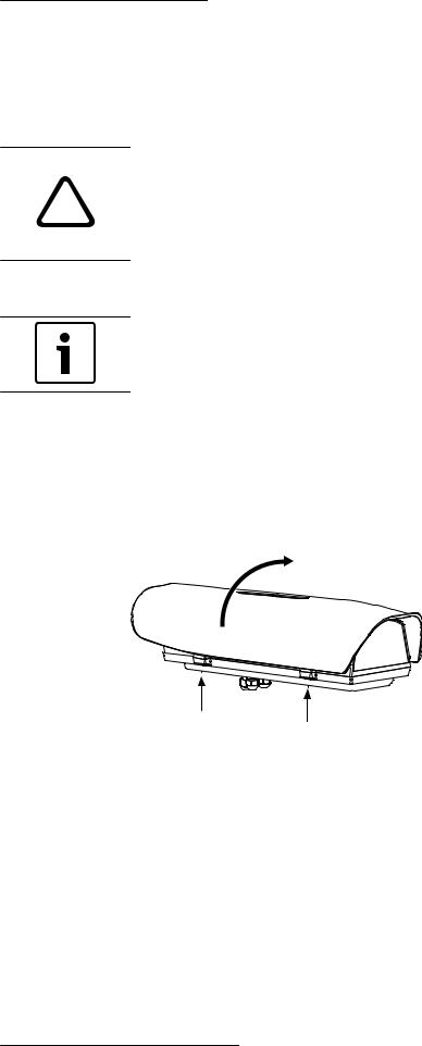
1. Open the housing by loosening the captive screws on the side and swivel the upper body until it is completely open (do not remove screws completely).
Figure 4.1: Loosen Screws and Open Lid of Housing
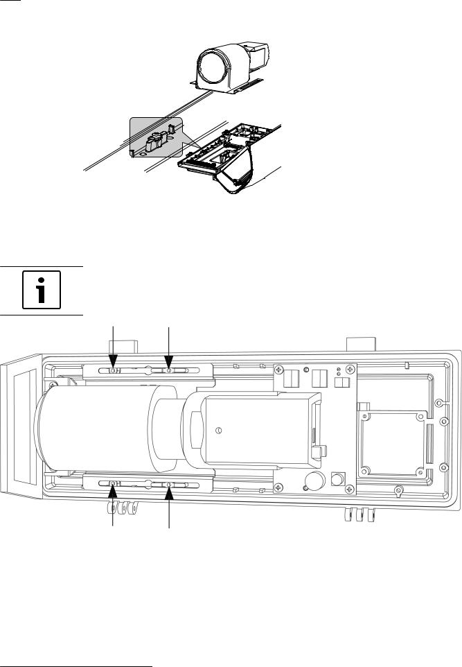
2.Remove the camera/lens mounting tray from the packing box.
3.Install the camera/lens mounting tray attached in the correct position inside the housing at the location shown below.
Bosch Security Systems, Inc. |
Operation Manual |
2013.11 | 5.2 | F.01U.291.981 |
16 en | Installing the Camera/Lens |
High-Speed Positioning System |
|
(HSPS) |
||
|
||
|
|
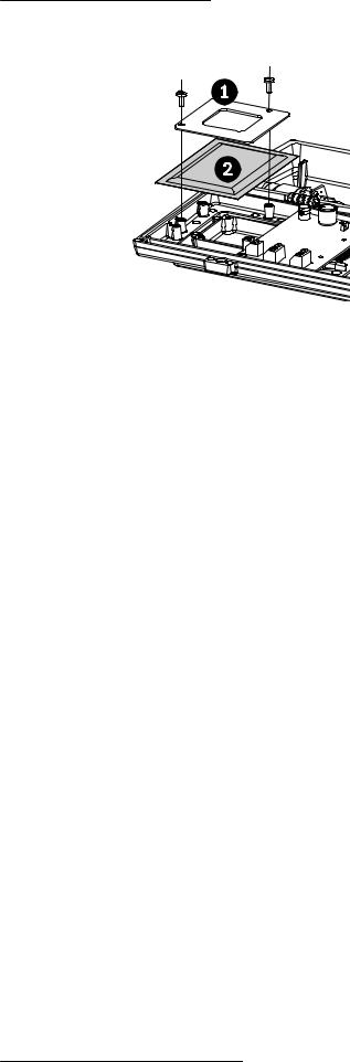
Figure 4.2: Install Camera/Tray
4.Reposition the camera/lens mounting tray by sliding it forward so that the lens is as close to the front window as possible. Insert and tighten the four M4 x 10 screws and the four washers (contained in the Cable and Screws accessory bag) as shown in the figure “Attach Camera to Housing” below.
Notice!
A partially blocked view may result if the camera is not pushed up close to the front of the housing.
Figure 4.3: Attach Camera to Housing
5.Locate the sealed plastic bag containing the desiccant bag.
6.Place the desiccant bag inside the housing as shown in the figure below, with the desiccant bag secured into position by the metal fixing accessory and two fixing screws (supplied in the Desiccant accessory bag).
2013.11 | 5.2 | F.01U.291.981 |
Operation Manual |
Bosch Security Systems, Inc. |
High-Speed Positioning System |
Installing the Camera/Lens | en 17 |
|
(HSPS) |
||
|
||
|
|
Figure 4.4: Attach Desiccant Bag |
|
|
|
Reference # |
Description |
|
|
1 |
Bracket |
|
|
2 |
Desiccant Bag |
|
|
4.2 |
Preparing the Camera |
|
|
1. |
Remove the camera packaging material. |
|
2. |
Make sure that the gasket is present and in good condition. |
Bosch Security Systems, Inc. |
Operation Manual |
2013.11 | 5.2 | F.01U.291.981 |

18 en | Installing the Camera/Lens |
High-Speed Positioning System |
|
(HSPS) |
||
|
||
|
|
4.3 Connecting the Camera and Motorized Lens
J27
J26
J1
Figure 4.5: Make Connections (LTC 0498 Dinion 2X camera shown)
Reference |
Description |
|
|
1 |
8-pin DIN connector |
|
|
2 |
4-pin iris override connector |
|
|
3 |
2-pin power cable |
|
|
4 |
4-pin alarm cable |
|
|
5 |
VIDEO IN connector |
|
|
1.Connect the 8-pin DIN connector zoom and focus control cable from the camera to the J5 location on the board. Secure cable in up-right position by using supplied tie wrap.
2.If applicable (LTC 3293/30 manual override units only), connect the 4-pin iris override connector from the camera to the J2 location on the board.
3.Connect the 2-pin power cable from the camera to the mating connector from the J26 location on the board.
2013.11 | 5.2 | F.01U.291.981 |
Operation Manual |
Bosch Security Systems, Inc. |

High-Speed Positioning System |
Installing the Camera/Lens | en 19 |
|
(HSPS) |
||
|
||
|
|
4.Connect the 4-pin alarm cable from the camera to the mating connector from the J27 location on the board.
5.Connect the “L” adapter end of the coax cable (supplied in the Cable and Screw accessory bag) to the coax connector on the back of the camera. VIDEO IN connector from the camera to the J1 location on the board.
6.Route the other end of the coax cable along the right side (looking from behind) of the camera and under the camera tray. Then, connect the coax cable to the J1 location on the board.
7.Wrap one of the 102 x 2.5 mm tie wraps around the zoom and focus cable and the coax cable, near the location where the cables connect to the board.
8.Close and secure the housing lid.
Bosch Security Systems, Inc. |
Operation Manual |
2013.11 | 5.2 | F.01U.291.981 |

20 en | Installing the High Speed Positioning System |
High-Speed Positioning System |
|
(HSPS) |
||
|
||
|
|
5 Installing the High Speed Positioning System
This chapter outlines the procedures needed to mount the High Speed Positioning System.
Caution!
Installation must be made by qualified personnel and conform to ANSI/NFPA 70 (the National
!Electrical Code® (NEC)), Canadian Electrical Code, Part I (also called CE Code or CSA C22.1), and all applicable local codes. Bosch Security Systems, Inc. accepts no liability for any damages or losses caused by incorrect or improper installation.
Notice!
The High-speed Positioning System device cannot be mounted upside down! This configuration stresses bearings and mechanical components; no liabilities are accepted and all warranties are void.
Notice!
In accordance with NEC laws, you may be required to install an external power junction box.
The following warnings apply to the device itself, the video cable, and the connections for Biphase and for RS-422/Pelco D.
Warning!
! The installation is type TNV-1. Do not connect it to SELV circuits.
Warning!
The installation is type CDS (Cable Distribution System). Do not connect it to SELV circuits.
!In order to reduce the risk of fire, only use UL Listed or CSA certified telecommunication line cord sizes greater than or equal to 26 AWG.
5.1 Mounting the High Speed Positioning System
The High Speed Positioning System can be mounted with either a wall mount (MTC-WUPH, sold separately) or a pole mount (MTC-PUPH, sold separately).
The figure below illustrates the configuration of the mount, the support for the washer pipe for the optional washer kit, and the base of the device.
2013.11 | 5.2 | F.01U.291.981 |
Operation Manual |
Bosch Security Systems, Inc. |
High-Speed Positioning System |
|
Installing the High Speed Positioning System | en 21 |
|||||||||||||||||||||||||||||||
(HSPS) |
|
||||||||||||||||||||||||||||||||
|
|
|
|
|
|||||||||||||||||||||||||||||
|
|
|
|
|
|
|
|
|
|
|
|
|
|
|
|
|
|
|
|
|
|
|
|
|
|
|
|
|
|
|
|
|
|
|
|
|
|
|
|
|
|
|
|
|
|
|
|
|
|
|
|
|
|
|
|
|
|
|
|
|
|
|
|
|
|
|
|
|
|
|
|
|
|
|
|
|
|
|
|
|
|
|
|
|
|
|
|
|
|
|
|
|
|
|
|
|
|
|
|
|
|
|
|
|
|
|
|
|
|
|
|
|
|
|
|
|
|
|
|
|
|
|
|
|
|
|
|
|
|
|
|
|
|
|
|
|
|
|
|
|
|
|
|
|
|
|
|
|
|
|
|
|
|
|
|
|
|
|
|
|
|
|
|
|
|
|
|
|
|
|
|
|
|
|
|
|
|
|
|
|
|
|
|
|
|
|
|
|
|
|
|
|
|
|
|
|
|
|
|
|
|
|
|
|
|
|
|
|
|
|
|
|
|
|
|
|
|
|
|
|
|
|
|
|
|
|
|
|
|
|
|
|
|
|
|
|
|
|
|
|
|
|
|
|
|
|
|
|
|
|
|
|
|
|
|
|
|
|
|
|
|
|
|
|
|
|
|
|
|
|
|
|
|
|
|
|
|
|
|
|
|
|
|
|
|
|
|
|
|
|
|
|
|
|
|
|
|
|
|
|
|
|
|
|
|
|
|
|
|
|
|
|
|
|
|
|
|
|
|
|
|
|
|
|
|
|
|
|
|
|
|
|
|
|
|
|
|
|
|
|
|
|
|
|
|
|
|
|
|
|
|
|
|
|
|
|
|
|
|
|
|
|
|
|
|
|
|
|
|
|
|
|
|
|
|
|
|
|
|
|
|
|
|
|
|
|
|
|
|
|
|
|
|
|
|
|
|
|
|
|
|
|
|
|
|
|
|
|
|
|
|
|
|
|
|
|
|
|
|
|
|
|
|
|
|
|
|
|
|
|
|
|
|
|
|
|
|
|
|
|
|
|
|
|
|
|
|
|
|
|
|
|
|
|
|
|
|
|
|
|
|
|
|
|
|
|
|
|
|
|
|
|
|
|
|
|
|
|
|
|
|
|
|
|
|
|
|
|
|
|
|
|
|
|
|
|
|
|
|
|
|
|
|
|
|
|
|
|
|
|
|
|
|
|
|
|
|
|
|
|
|
|
|
|
|
|
|
|
|
|
|
|
|
|
|
|
|
|
|
|
|
|
|
|
|
|
|
|
|
|
|
|
|
|
|
|
|
|
|
|
|
|
|
|
|
|
|
|
|
|
|
|
|
|
|
|
|
|
|
|
|
|
|
|
|
|
|
|
|
|
|
|
|
|
|
|
|
|
|
|
|
|
|
|
|
|
|
|
|
|
|
|
|
|
|
|
|
|
|
|
|
|
|
|
|
|
|
|
|
|
|
|
|
|
|
|
|
|
|
|
|
|
|
|
|
|
|
|
|
|
|
|
|
|
|
|
|
|
|
|
|
|
|
|
|
|
|
|
|
|
|
|
|
|
|
|
|
|
|
|
|
|
|
|
|
|
|
|
|
|
|
|
|
|
|
|
|
|
|
|
|
|
|
|
|
|
|
|
|
|
|
|
|
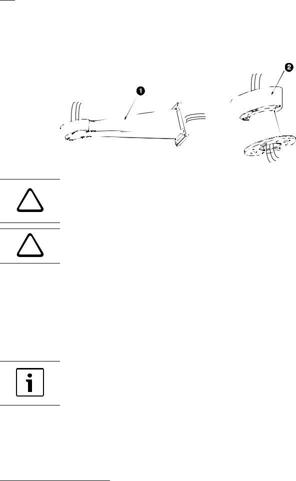
Figure 5.1: Diagram of mount, washer support, base
|
1 |
Support for MTC-WUPH (wall mount) or MTC-PUPH (pole mount) |
|
|
|
|
2 |
Cable glands |
|
|
|
|
3 |
Support for the washer pipe for the optional washer kit |
|
|
|
|
4 |
Base |
|
|
|
|
5 |
Screws (4) |
|
|
|
|
6 |
Washers (4) |
|
|
|
|
7 |
Screw seals (4) |
|
|
|
|
8 |
Gasket |
|
|
|
|
|
|
Warning!
Take special care when attaching and fastening down the device.
Fixing dowel pins with a traction torque rating/load of at least 300 dN each are required: - When the MTC-WUPH Wall Mount is fixed to a wall.
!- If the mount is to be attached to a concrete surface.
For a metal surface, use screws/bolts with a diameter of at least 8 mm and of an appropriate length. The clamping system must support at least four times the weight of the entire equipment, including the pan and tilt head, lenses, and camera.
Installing the mount
To install the device, follow these steps:
1.Determine the location to install the device.
When selecting a location, a minimum clearance of 300 mm (12 in.) in front of the device and 300 mm (12 in.) in back of the device is required to facilitate component removal and installation.
The device should be installed vertically. Any other position could impair the performance of the device.
Do not attach the device upside down.
Bosch Security Systems, Inc. |
Operation Manual |
2013.11 | 5.2 | F.01U.291.981 |
22 en | Installing the High Speed Positioning System |
High-Speed Positioning System |
|
(HSPS) |
||
|
||
|
|
2.Insert the cables into the optional wall or pole mount so that they protrude approximately 0.5 m (19.7 in.).
0 .5 3 M (1 9 .7 IN.)
0 .5 3 M (1 9 .7 IN.)
1
MTC-PUPH
2
MTC-WUPH
Figure 5.2: Optional Wall Mount (1) or Pole Mount (2)
Warning!
The cables should not be accessible by unauthorized personnel; cables should be secured to
!fixed locations at appropriate intervals to bare the weight of the cables, for example, cables running inside a tall camera pole.
Warning!
!Be sure to use appropriately strong and load-bearing bolts and other fixing materials when installing any UPH mountings to any surface.
3. Attach the optional wall or pole mount according to the specific mounting manual.
Part |
Description |
|
|
MTC-PUPH |
Outdoor Pole Mount for UPH Series |
|
|
MTC-WUPH |
Outdoor Wall Mount for UPH Series |
|
|
MTC-POLE-W |
Pole Adapter for MTC-WUPH |
|
|
MTC-CORN-W |
Corner Adapter for MTC-WUPH |
|
|
Installing the optional washer kit
Notice!
If using a washer kit (optional, sold separately), you must install the support for the washer pipe before positioning and wiring the pan/tilt. Refer to the Installation Manual for the Washer Kit.
Installing the HSPS base on the mount
1.Remove the desiccant bag from inside the base and discard.
2.Remove the cable glands from the base and fit the gasket / seal ring.
3.Insert the cables into the cable glands while holding the base approximately 20 cm from the bracket. Note that there are three glands; one for power, one for video, and one for data / IO cables.
2013.11 | 5.2 | F.01U.291.981 |
Operation Manual |
Bosch Security Systems, Inc. |
High-Speed Positioning System |
Installing the High Speed Positioning System | en 23 |
|
(HSPS) |
||
|
||
|
|
4.Securely lock the cable glands into place, using a gland closing torque of 5 N m. Use a calibrated torque wrench to ensure closure.
Note: The cable glands accept cables 5-10 mm (0.2-0.39 in.) in diameter. They can be changed to accept smaller 3-7 mm diameter cables by using the two (2) conduit plugs (supplied).
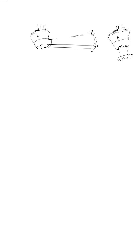
5.Position the base on the optional wall or pole mount, guiding the cables so that they are positioned inside the wall or pole mount (see the figure Schematic Diagram below).
|
|
|
1 |
|
1 |
6 |
|
|
|
|
|
2 |
|
2 |
7 |
|
|
|
|
3 |
|
3 |
|
|
|
|
|
|
|
4 |
|
4
5
5
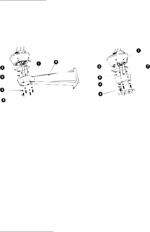
Figure 5.3: Schematic Diagram
Reference |
Description |
|
|
1 |
Base |
|
|
2 |
Gasket |
|
|
3 |
Screw seals |
|
(4) |
|
|
4 |
Washers (4) |
|
|
5 |
Screws (4) |
|
|
6 |
Bracket |
|
|
7 |
Support |
|
|
Securing the base to the mount
1.Apply thread locker (such as Loctite 243) on the holes of the screws.
2.Secure the base to the wall or pole mount with the screws and washers (supplied).
3.Tighten the screws to 4 N m using a calibrated torque wrench.
Bosch Security Systems, Inc. |
Operation Manual |
2013.11 | 5.2 | F.01U.291.981 |
24 en | Installing the High Speed Positioning System |
High-Speed Positioning System |
|
(HSPS) |
||
|
||
|
|
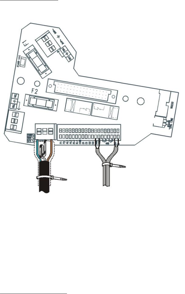
5.2 Wiring the Device
Figure 5.4: Preparing the Cables for Wiring
1.Cut the cables to approximately 152.4 mm (6 in.) (see the figure Preparing the Cables for Wiring, above). The earth cable must be longer than the power wires by approximately 10 mm or more to prevent disconnection.
2.Cover the power cable with the plastic tube supplied. Fix it with the tie thread.
3.Make a group with all signal cables and fix them with the tie thread. See the illustration below for a proper cable connection.
Note: IR360 version boards will vary slightly because the signals connector has 16 lines as instead of 19, as shown below.
2013.11 | 5.2 | F.01U.291.981 |
Operation Manual |
Bosch Security Systems, Inc. |
High-Speed Positioning System |
Installing the High Speed Positioning System | en 25 |
|
(HSPS) |
||
|
||
|
|
Figure 5.5: Tie Threads used to Group and Secure Cables
5.3 |
Wiring the Video Cable |
|
|
Note: The terminals support AWG 20 (0.5 mm2) to AWG 28 (0.08 mm2) cables. |
|
|
To wire the video cable, follow these steps: |
|
|
1. |
Locate the coaxial termination cable that is in the Cable and Screws accessory bag. |
|
2. |
Use a small screwdriver to press down on the GND push latch (see the figure) and attach |
|
|
the black ground wire to the GND terminal. |
|
3. |
Use a small screwdriver to press down on the VIDEO push latch (see group 101) and |
|
|
attach the clear coaxial conductor to the VIDEO terminal. |
|
4. |
Retract the shield covering the female BNC connector and route the coaxial termination |
|
|
cable into the base of the device. |
|
5. |
Route the incoming coaxial cable with a male BNC connector into the base and connect |
|
|
to the female BNC connector on the coaxial termination cable. |
|
6. |
Move the shield to cover the coaxial connection. |
Bosch Security Systems, Inc. |
Operation Manual |
2013.11 | 5.2 | F.01U.291.981 |
Loading...