


GSH 11 E
EURO • Printed in Germany • BA 1 619 929 581 • GSH 11 E • Titel (Vorderseite) • OSW 02.04
Bedienungsanleitung
Operating Instructions
Instructions d’emploi
Instrucciones de servicio
Manual de instruções
Istruzioni d’uso
Gebruiksaanwijzing
Betjeningsvejledning
Bruksanvisning
Brukerveiledningen
Käyttöohje
Oδηγία χειρισµού
Kullanım kılavuzu
Deutsch
English
Français
Español
Português
Italiano
Nederlands
Dansk
Svenska
Norsk
Suomi
Eλληνικά
Türkçe
GSH 11 E
GSH 11 (581) Titel Vorderseite Seite 1 Montag, 22. April 2002 2:12 14

2 • 1 619 929 581 • 02.04
A
2
B
C
3 • 1 619 929 581 • 02.04
5
6
1
2
7
4
3
GSH 11 E
Deutsch - 1
Messwerte ermittelt entsprechend 2000/14/EG
(1,60 m Höhe, 1 m Abstand) und EN 50 144.
Der A-bewertete Geräuschpegel des Gerätes beträgt typischerweise: Schalldruckpegel 88 dB (A);
Schallleistungspegel 101 dB (A).
Gehörschutz tragen!
Die bewertete Beschleunigung beträgt typischerweise 14 m/s
2
.
Das Gerät ist bestimmt für Meißelarbeiten in Beton, Ziegel, Gestein und Asphalt sowie mit entsprechendem Zubehör auch zum Eintreiben und
Verdichten.
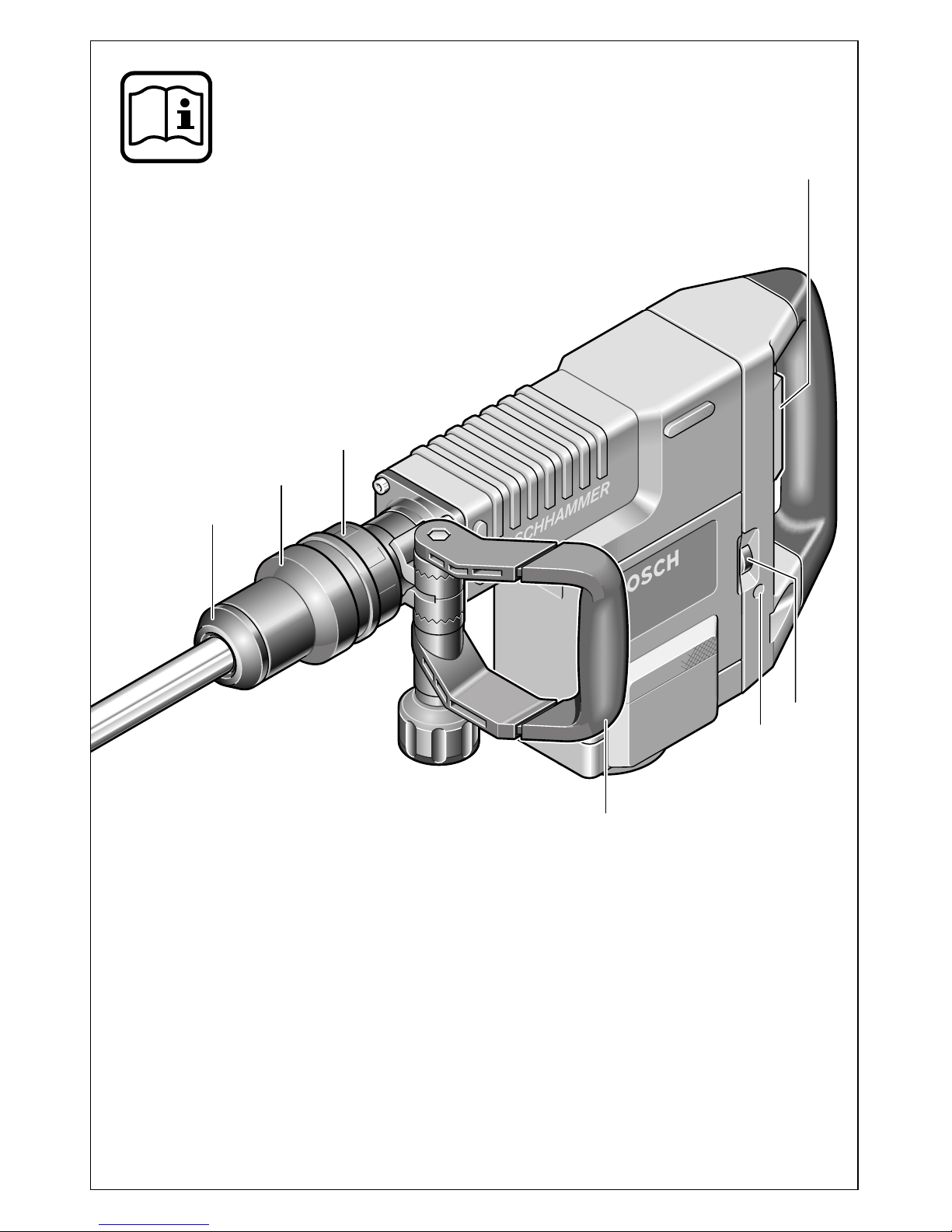
1
Staubschutzkappe
2
Verriegelungshülse
3
Meißelverstellring (Vario-lock)
4
Ein-/Ausschalter
5
Schlagzahlregler
6
Service-Anzeige
7
Zusatzgriff
Abgebildetes oder beschriebenes Zubehör gehört
teilweise nicht zum Lieferumfang.
Gefahrloses Arbeiten mit dem
Gerät ist nur möglich, wenn Sie
die Bedienungsanleitung und
die Sicherheitshinweise vollständig lesen und die darin enthaltenen Anweisungen strikt befolgen. Lassen Sie sich vor dem
ersten Gebrauch praktisch einweisen. Zusätzlich müssen die
allgemeinen Sicherheitshinweise im beigefügten Heft befolgt werden.
■
Gehörschutz tragen.
■
Schutzbrille, Schutzhandschuhe und festes
Schuhwerk tragen.
■
Wird bei der Arbeit das Netzkabel beschädigt
oder durchtrennt, Kabel nicht berühren, sondern sofort den Netzstecker ziehen. Gerät niemals mit beschädigtem Kabel benutzen.
■
Geräte, die im Freien verwendet werden, über
einen Fehlerstrom-Schutzschalter (FI-) mit
maximal 30 mA Auslösestrom anschließen.
Nur ein für den Außenbereich zugelassenes
Verlängerungskabel verwenden.
■
Verwenden Sie geeignete Suchgeräte, um
verborgene Versorgungsleitungen aufzuspüren, oder ziehen Sie die örtliche Versorgungsgesellschaft hinzu.
Kontakt mit Elektroleitungen kann zu Feuer
und elektrischem Schlag führen. Beschädigung einer Gasleitung kann zur Explosion
führen. Eindringen in eine Wasserleitung verursacht Sachbeschädigung oder kann einen
elektrischen Schlag verursachen.
■
Das Elektrowerkzeug nur an isolierten
Handgriffen anfassen, wenn das Einsatzwerkzeug eine verborgene Leitung oder
das eigene Netzkabel treffen kann.
Kontakt mit einer spannungsführenden Leitung kann Metallteile des Gerätes unter Spannung setzen und zu einem elektrischen Schlag
führen.
■
Kabel immer nach hinten vom Gerät wegführen.
■
Stecker nur bei ausgeschaltetem Gerät in die
Steckdose einstecken.
■
Gerät nur mit Zusatzgriff 7 verwenden.
■
Beim Arbeiten das Gerät immer fest mit beiden
Händen halten und für einen sicheren Stand
sorgen.
Gerätekennwerte
Schlaghammer GSH 11 E
Bestellnummer 0 611 316 7..
Nennaufnahme [W] 1 500
Schlagzahl [/min] 900–1 890
Einzelschlagstärke [J] 6–25
Meißelstellungen 12
Meißelleistung in Beton
mittlerer Härte
[cm
3
/
min]
2 700
Werkzeugaufnahme SDS-max
Schmierung Zentrale Dauer-
schmierung
Gewicht
(ohne Zubehör) ca.
[kg] 10,1
Schutzklasse
/ II
Bitte die Bestellnummer Ihrer Maschine beachten. Die
Handelsbezeichnungen einzelner Maschinen können
variieren.
Geräusch-/Vibrationsinformation
Bestimmungsgemäßer Gebrauch
Geräteelemente
Zu Ihrer Sicherheit
4 • 1 619 929 581 • TMS • 15.04.02

Deutsch - 2
■ Das Gerät vor dem Ablegen immer ausschal-
ten und warten bis das Gerät zum Stillstand
gekommen ist.
■
Niemals Kindern die Benutzung des Gerätes
gestatten.
■
Bosch kann nur dann eine einwandfreie Funktion des Gerätes zusichern, wenn das für dieses Gerät vorgesehene Original-Zubehör verwendet wird.
■
Gerät nur mit Zusatzgriff 7 verwenden.
Der Zusatzgriff 7 lässt sich durch Lösen der Rändelmutter um die Geräteachse schwenken und
somit der Arbeitsposition anpassen.
Für Linkshänder lässt sich der Zusatzgriff
7
um-
montieren:
Dazu die Rändelmutter ganz abschrauben. Da-
nach die Sechskantschraube nach oben herausziehen.
Den Zusatzgriff
7
seitlich abziehen und verblei-
bendes Spannteil um 180° schwenken.
Den Zusatzgriff
7
in umgekehrter Reihenfolge
wieder montieren.
■
Vor allen Arbeiten am Gerät Netzstecker
ziehen.
Mit der Werkzeugaufnahme SDS-max ist ein einfacher, bequemer Werkzeugwechsel möglich,
ohne Hilfe zusätzlicher Werkzeuge.
☞
Das Einsteckende der Werkzeuge ist regelmäßig zu fetten.
Die Staubschutzkappe 1 verhindert weitgehend
das Eindringen von Bohrstaub während des Betriebes. Beim Einsetzen des Werkzeuges darauf
achten, dass die Staubschutzkappe
1
nicht be-
schädigt wird.
Eine beschädigte Staubschutzkappe ist sofort auszutauschen. Es wird empfohlen, dies
von einem Kundendienst vornehmen zu lassen.
Einsetzen (siehe Bild )
Das Einsteckende des Werkzeuges reinigen
und fetten.
Das Werkzeug drehend in die Werkzeugaufnahme einführen bis es selbsttätig verriegelt
wird. Die Verriegelung durch Ziehen am Werkzeug prüfen.
Entnehmen (siehe Bild )
Die Verriegelungshülse 2 der Werkzeugaufnahme nach hinten schieben und das Werkzeug
entnehmen. Die Verriegelungshülse
2
wieder
loslassen.
Netzspannung beachten: Die Spannung der
Stromquelle muss mit den Angaben auf dem
Typschild des Gerätes übereinstimmen. Mit
230 V gekennzeichnete Geräte können auch an
220 V betrieben werden.
Ein-/Ausschalten
Zur Inbetriebnahme des Gerätes den Ein-/Ausschalter
4
nach rechts schieben.
Zum
Ausschalten des Gerätes den Ein-/Aus-
schalter
4
nach links schieben.
☞
Bei niedrigen Temperaturen erreicht das
Gerät erst nach einer gewissen Zeit die
volle Schlagleistung.
Diese Anlaufzeit kann verkürzt werden, indem der Meißel einmal auf den Boden gestoßen wird.
Zusatzgriff
Werkzeugwechsel
Inbetriebnahme
A
B
5 • 1 619 929 581 • TMS • 15.04.02

Deutsch - 3
Die Regelelektronik ermöglicht eine stufenlose
Schlagzahlvorwahl für materialgerechtes Arbeiten. Die Einstellung erfolgt mit dem Schlagzahlregler
5
.
Die Konstantelektronik hält die vorgewählte
Schlagzahl zwischen Leerlauf und Last nahezu
konstant.
Die Schlagzahl muss dem Material entsprechend
ausgewählt werden.
Alle Angaben sind ca.-Werte.
Der Meißel lässt sich in 12 Stellungen arretieren.
Dadurch kann die jeweils optimale Arbeitsstellung eingenommen werden.
Dazu den Meißelverstellring
3
nach vorne schieben und festhalten, dann mit dem Meißelverstellring
3
den Meißel drehen, bis die gewünschte
Position erreicht ist.
Den Meißelverstellring
3
loslassen und den Mei-
ßel drehen bis er einrastet.
Nur mit scharfen Meißelwerkzeugen erzielt man
gute Ergebnisse, deshalb die Meißelwerkzeuge
rechtzeitig schärfen. Das gewährleistet hohe
Standzeiten der Werkzeuge und gute Arbeitsleistungen.
Nachschleifen
Die Meißelwerkzeuge an Schleifscheiben (zum
Beispiel Edelkorund) unter gleichbleibender
Wasserzufuhr schleifen. Richtwerte hierfür enthält Bild C. Darauf achten, dass sich an den
Schneiden keine Anlassfarben zeigen, das beeinträchtigt die Härte der Meißelwerkzeuge.
Schmieden und Härten
Schmieden: Meißel auf 850 bis 1050 °C (hellrot
bis gelb) erhitzen und schmieden.
Härten:
Meißel auf 900 °C (hellrot) erhitzen
und in Öl abschrecken, danach im
Ofen ca. eine Stunde bei 320 °C
(Anlassfarbe hellblau) anlassen.
■
Vor allen Arbeiten am Gerät Netzstecker
ziehen.
☞
Gerät und Lüftungsschlitze stets sauber
halten, um gut und sicher zu arbeiten.
■
Werkzeugaufnahme immer sauber halten.
Staubschutzkappe wechseln
Eine beschädigte Staubschutzkappe ist sofort
auszutauschen. Es wird empfohlen, dies von einem Kundendienst vornehmen zu lassen.
Service-Anzeige 6
Bei verbrauchten Kohlen schaltet das Gerät
selbsttätig ab. Dies wird ca. 8 Stunden vorher
durch Aufleuchten oder Flackern der Service-Anzeige
6
angezeigt. Das Gerät muss zur Wartung
an den Kundendienst geschickt werden (Anschrift siehe Abschnitt „Service und Kundenberater“).
Sollte das Gerät trotz sorgfältiger Herstellungsund Prüfverfahren einmal ausfallen, ist die Reparatur von einer autorisierten Kundendienststelle
für Bosch-Elektrowerkzeuge ausführen zu lassen.
Bei allen Rückfragen und Ersatzteilbestellungen
bitte unbedingt die 10-stellige Bestellnummer laut
Typenschild des Gerätes angeben.
Schlagzahl ändern
Anwendungsbereich
Reglerstellung
Schlagzahl
(/min)
Verputz/
Leichtbaustoffe
1–2 950–1 180
Ablösen von Fliesen 3 1 380
Ziegelsteine 4 1 520
Beton 5–6 1 710–1 890
Meißelstellung verändern
(Vario-lock)
Schärfen der Meißelwerkzeuge
Wartung und Reinigung
6 • 1 619 929 581 • TMS • 15.04.02
Deutsch - 4
Rohstoffrückgewinnung statt Müllentsorgung
Gerät, Zubehör und Verpackung sollten einer
umweltgerechten Wiederverwertung zugeführt
werden.
Diese Anleitung ist aus chlorfrei gefertigtem Recycling-Papier hergestellt.
Zum sortenreinen Recycling sind Kunststoffteile
gekennzeichnet.
In Deutschland sind nicht mehr gebrauchsfähige
Geräte zum Recycling beim Handel abzugeben
oder (ausreichend frankiert) direkt einzuschicken
an:
Recyclingzentrum Elektrowerkzeuge
Osteroder Landstraße 3
37589 Kalefeld
www.powertool-portal.de , das Internetportal
für Handwerker und Heimwerker
www.ewbc.de , der Informations-Pool für Hand-
werk und Ausbildung
Deutschland
Robert Bosch GmbH
Servicezentrum Elektrowerkzeuge
Zur Luhne 2
D-37589 Kalefeld
✆
Service:
.......................................
01 80 - 3 35 54 99
Fax
.............................................
+49 (0) 55 53 / 20 22 37
✆ Kundenberater:...................... 01 80 - 3 33 57 99
Österreich
ABE Service GmbH
Jochen-Rindt-Straße 1
A-1232 Wien
✆ Service:..................................... +43 (0)1 / 61 03 80
Fax
................................................. +43 (0)1 / 61 03 84 91
✆ Kundenberater:............ +43 (0)1 / 797 22 3066
E-Mail: abe@abe-service.co.at
Schweiz
Robert Bosch AG
Kundendienst Elektrowerkzeuge
Industriestrasse 31
CH-8112 Otelfingen
✆ Service:................................. +41 (0)1 / 8 47 16 16
✆ Kundenberater:...... Grüne Nr. 0 800 55 11 55
Wir erklären in alleiniger Verantwortung, dass
dieses Produkt mit den folgenden Normen oder
normativen Dokumenten übereinstimmt:
EN 50 144 gemäß den Bestimmungen der Richtlinien 89/336/EWG, 98/37/EG, 2000/14/EG.
2000/14/EG: Der garantierte Schallleistungspegel L
WA
ist niedriger als 107 dB (A). Bewertungs-
verfahren der Konformität gemäß Anhang VI.
Benannte Prüfstelle:
TÜV Hannover/Sachsen-Anhalt e.V.,
D-30519 Hannover CE-DE10-139 670
Leinfelden, 01.03.2002.
Dr. Gerhard Felten Dr. Eckerhard Strötgen
Entwicklungsleiter Leiter Produktzulassung
Robert Bosch GmbH, Geschäftsbereich Elektrowerkzeuge
Änderungen vorbehalten
Umweltschutz Service und Kundenberater
Konformitätserklärung
7 • 1 619 929 581 • TMS • 15.04.02
English - 1
Measured values determined according to
2000/14/EC (1.60 m height, 1 m distance away)
and EN 50 144.
Typically the A-weighted noise levels of the product are: sound pressure level: 88 dB (A); sound
power level: 101 dB (A).
Wear hearing protection!
The typical weighted acceleration is 14 m/s
2
.
The machine is intended for chiselling work in
concrete, brick, stone and asphalt as well as for
driving and compacting with appropriate accessories.
1 Dust protection cap
2 Locking sleeve
3 Chisel adjusting ring (Vario-lock)
4 On/Off switch
5 Impact rate control
6 Service indicator
7 Auxiliary handle
Not all of the accessories illustrated or described are
included as standard delivery.
Working safely with this machine is possible only when the
operating and safety information
are read completely and the instructions contained therein are
strictly followed. Before using
for the first time, ask for a practical demonstration. In addition,
the general safety notes in the
enclosed booklet must be observed.
■ Wear hearing protection.
■ Wear safety glasses, protective gloves and
sturdy shoes.
■ If the mains cable is damaged or cut through
while working, do not touch the cable but immediately pull the mains plug. Never use the
machine with a damaged cable.
■ Connect machines that are used in the open
via a residual current device (RCD) with an actuating current of 30 mA maximum. Use only
extension cables that are approved for outdoor
use.
■ Use appropriate detectors to determine if
utility lines are hidden in the work area or
call the local utility company for assistance.
Contact with electric lines can lead to fire and
electric shock. Damaging a gas line can lead to
explosion. Penetrating a water line causes
property damage or may cause an electric
shock.
■ Hold the power tool only by the insulated
gripping surfaces, when performing an operation where the cutting tool may run into
hidden wiring or its own cord.
Contact with a “live” wire will make exposed
metal parts of the tool “live” and shock the operator.
■ Always direct the cable to the rear away from
the machine.
■ Insert the mains plug only when the machine is
switched off.
■ Use the machine only with the auxiliary handle 7.
■ When working with the machine, always hold it
firmly with both hands and provide for a secure
stance.
■ Always switch the machine off and wait until it
has come to a standstill before placing it down.
■ Never allow children to use the machine.
■ Bosch is only able to ensure perfect operation
of the machine if the original accessories intended for it are used.
Tool Specifications
Demolition Hammer GSH 11 E
Order number 0 611 316 7..
Rated power [W] 1 500
Impact rate [bpm] 900–1 890
Impact energy per
stroke
[J] 6–25
Chisel positions 12
Chiselling performance
in concrete of medium
hardness
[cm3/
min]
2 700
Tool holder SDS-max
Lubrication Permanent
central
lubrication
Weight (without
accessories) approx.
[kg] 10.1
Protection class / II
Please observe the order number of your machine.
The trade names of the individual machines may vary.
Noise/Vibration Information
Intended Use
Machine Elements
For Your Safety
8 • 1 619 929 581 • TMS • 15.04.02

English - 2
■ Use the machine only with the auxiliary
handle 7.
The auxiliary handle 7 can be rotated around the
axis of the machine after loosening the knurled
nut and adapted to the working position in this
manner.
The auxiliary handle 7 can be remounted to suit
left-handed users:
For this purpose, unscrew the knob completely
and then remove the hex-head bolt by pulling upward.
Pull off the auxiliary handle 7 to the side and rotate the remaining clamping part by 180 degrees.
Remount the auxiliary handle 7 in the reverse order.
■ Before any work on the machine itself, pull
the mains plug.
With the SDS-max tool holder, simpler and easier
tool changing is possible without additional aids.
☞
Grease the shank end of the tool regularly.
The dust protection cap 1 largely prevents the
entry of drilling dust during operation. When inserting the tool, take care that the dust protection
cap 1 is not damaged.
A damaged dust protection cap should be
changed immediately. We recommend having
this carried out by an after-sales service.
Inserting (see figure )
Clean and grease the shank end of the tool.
Insert the tool in a twisting manner into the tool
holder until it locks. Check if it has locked by pulling the tool.
Removing (see figure )
Push back the locking sleeve 2 of the tool holder
and remove the tool. Let go of the locking
sleeve 2 again.
Observe correct mains voltage: The voltage of
the power source must agree with the voltage
specified on the nameplate of the machine.
Equipment marked with 230 V can also be connected to 220 V.
Switching On and Off
For starting operation of the machine, push the
On/Off switch 4 to the right.
For starting operation of the machine, push the
On/Off switch 4 to the left.
☞
At low temperatures, the machine reaches
full impact rate only after a certain time.
This start-up time can be shortened by
striking the chisel against the floor once.
The electronic control makes possible the continuous selection of the impact rate in accordance
with the material to be worked. The setting is
made with impact rate control 5.
The constant electronic control keeps the preselected impact rate nearly constant between noload and load conditions.
The speed must be selected in accordance with
the material.
All values are approximate.
Auxiliary Handle
Changing the Tool
A
B
Initial Operation
Changing the Impact Rate
Area of Application Control
Setting
Impact Rate
(bpm)
Plaster/
lightweight materials
1–2 950–1 180
Removing tiles 3 1 380
Brick 4 1 520
Concrete 5–6 1 710–1 890
9 • 1 619 929 581 • TMS • 15.04.02
English - 3
The chisel can be locked in 12 positions. In this
manner, the optimum working position can be set
for each application.
Slide the chisel adjusting ring 3 forward and hold
firmly. Then turn the chisel with the chisel adjusting ring 3 until the desired position is reached.
Release the chisel adjusting ring 3 and turn the
chisel until it locks into place.
Good results are only achieved with sharp chisels, therefore sharpen the chiselling tools regulary. This prolongs the service life of the tools and
ensures good working performance.
Re-sharpening the Chiselling Tools
Sharpen chiselling tools using grinding wheels
(e. g. ceramic bonded corundum wheel) with a
steady supply of water. Recommended values
are shown in Fig. C. Take care that no annealing
coloration appears on the cutting edges, otherwise the hardness of the chiselling tools will be
impaired.
Forging and Hardening
Forging: Heat the chisel to between 850 and
1050 °C (bright red to yellow) and
forge.
Hardening: Heat the chisel to 900 °C (bright
red) and quench in oil, then anneal
in an oven for approx. one hour at
320 °C (annealing colour = light
blue).
■ Before any work on the machine itself, pull
the mains plug.
☞
For safe and proper working, always keep
the machine and the ventilation slots clean.
■ Keep the tool holder clean at all times.
Changing the Dust Protection Cap
A damaged dust protection cap should be
changed immediately. We recommend having
this carried out by an after-sales service.
Service Indicator 6
When the carbon brushes are worn out, the machine switches itself off. This is indicated approx.
eight hours beforehand by the lighting or blinking
of the service indicator 6. The machine must then
be sent to customer service for maintenance (for
addresses, see Section “Service and Customer
Assistance”).
If the machine should fail despite the care taken
in manufacturing and testing procedures, repair
should be carried out by an after-sales service
centre for Bosch power tools.
In all correspondence and spare parts orders,
please always include the 10-digit order number
given on the nameplate of the machine.
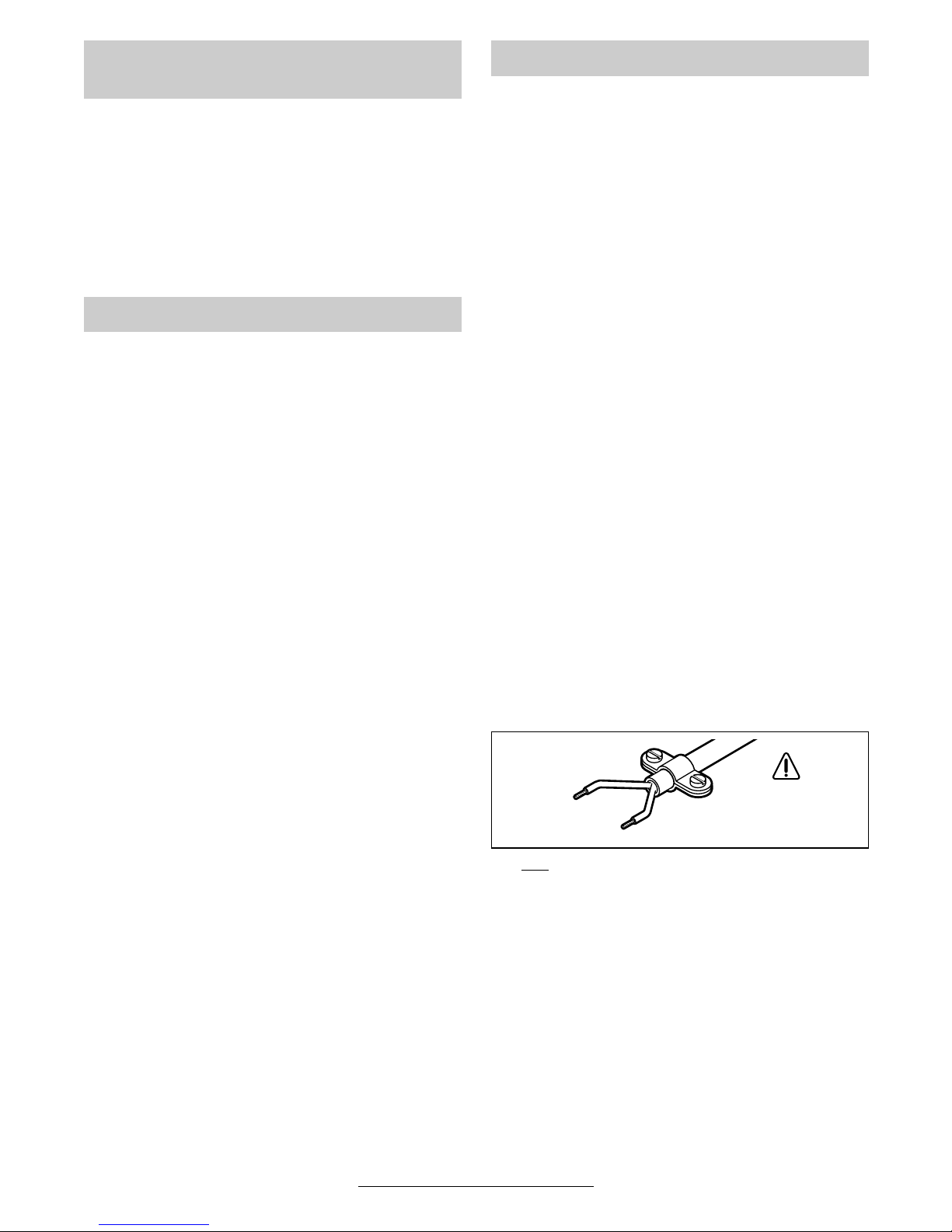
WARNING! Important instructions for connecting a new 3-pin plug to the 2-wire cable.
The wires in the cable are coloured according to
the following code:
Do not
connect the blue or brown wire to the
earth terminal of the plug.
Important: If for any reason the moulded plug is
removed from the cable of this machine it must be
disposed of safely.
Changing the Chiselling Position
(Vario-lock)
Sharpening Chisels
Maintenance and Cleaning
strain relief
live = brown
neutral = blue
To be fitted
by qualified
professional only
10 • 1 619 929 581 • TMS • 15.04.02
English - 4
Recycle raw materials instead of disposing as
waste
The machine, accessories and packaging should
be sorted for environmental-friendly recycling.
These instructions are printed on recycled paper
manufactured without chlorine.
The plastic components are labelled for categorized recycling.
Great Britain
Robert Bosch Ltd. (B.S.C.)
P.O. Box 98
Broadwater Park
North Orbital Road
Denham-Uxbridge
GB-Middlesex UB 9 5HJ
✆ Service............................ +44 (0)18 95 / 83 87 82
✆ Advice line.................... +44 (0)18 95 / 83 87 91
Fax
............................................. +44 (0)18 95 / 83 87 89
Ireland
Beaver Distribution Ltd.
Greenhills Road
IRL-Tallaght-Dublin 24
✆ Service................................... +353 (0)1 / 414 9400
Fax
.................................................... +353 (0)1 / 459 8030
Australia
Robert Bosch Australia L.t.d.
RBAU/SPT2
1555 Centre Road
P.O. Box 66 Clayton
AUS-3168 Clayton/Victoria
✆ ............................................... +61 (0)1 / 800 804 777
Fax
............................................... +61 (0)1 / 800 819 520
www.bosch.com.au
E-Mail: CustomerSupportSPT@au.bosch.com
New Zealand
Robert Bosch Limited
14-16 Constellation Drive
Mairangi Bay
Auckland
New Zealand
✆ ..................................................... +64 (0)9 / 47 86 158
Fax
..................................................... +64 (0)9 / 47 82 914
We declare under our sole responsibility that this
product is in conformity with the following standards or standardization documents: EN 50 144
according to the provisions of the directives
89/336/EEC, 98/37/EC, 2000/14/EC.
2000/14/EC: The guaranteed sound power
level L
WA
is lower than 107 dB (A). Conformity
assessment procedure according to Annex VI.
Notified body:
TÜV Hannover/Sachsen-Anhalt e.V.,
D-30519 Hannover CE-DE10-139 670
Leinfelden, 01.03.2002.
Dr. Gerhard Felten Dr. Eckerhard Strötgen
Senior Vice President Engineering Head of Product Certification
Robert Bosch GmbH, Geschäftsbereich Elektrowerkzeuge
Subject to change without notice
Environmental Protection
Service and
Customer Assistance
Declaration of Conformity
11 • 1 619 929 581 • TMS • 15.04.02

Français - 1
Valeurs de mesures obtenues conformément à la
2000/14/CE (mesure effectuée à une hauteur de
1,60 m et à 1 m de distance) et EN 50 144.
Les mesures réelles (A) des niveaux sonores de
la machine sont : intensité de bruit 88 dB (A). Niveau de bruit 101 dB (A).
Munissez-vous d’une protection acoustique !
L’accélération réelle mesurée est de 14 m/s
2
.
L’appareil est conçu pour des travaux de burinage dans le béton, la brique, la pierre naturelle
et l’asphalte ainsi que, lorsqu’il est muni d’accessoires adéquats, pour des travaux d’enfoncement et de compactage.
1 Capuchon anti-poussière
2 Douille de verrouillage
3 Bague d’ajustage du burin (Vario-lock)
4 Interrupteur Marche/Arrêt
5 Régulateur de frappe
6 Affichage travaux d’entretien
7 Poignée supplémentaire
Les accessoires reproduits ou décrits ne sont pas
forcément fournis avec la machine.
Pour travailler sans risque avec
cet appareil, lire intégralement
au préalable les instructions
d’utilisation et les remarques
concernant la sécurité. Respecter scrupuleusement les indications et les consignes qui y sont
données. Avant la première mise
en service, laisser quelqu’un
connaissant bien cet appareil
vous indiquer la façon de s’en
servir. Respecter en plus les indications générales de sécurité
se trouvant dans le cahier
ci-joint.
■ Porter une protection acoustique.
■ Porter des lunettes de protection et des gants
de protection. Mettre une paire de chaussures
solides.
■ Si le câble d’alimentation électrique est endommagé ou se rompt pendant le travail, ne
pas y toucher. Retirer immédiatement la fiche
du câble d’alimentation de la prise de courant.
Ne jamais utiliser un appareil dont le cordon
d’alimentation est endommagé.
■ Monter un disjoncteur différentiel (courant de
déclenchement : 30 mA max.) en amont des
appareils utilisés en plein air. N’utiliser qu’un
câble de rallonge électrique autorisé pour les
travaux à l’extérieur.
■ Utiliser des détecteurs appropriés afin de
déceler des conduites cachées ou consulter les entreprises d’approvisionnement locales.
Un contact avec des conduites d’électricité
peut provoquer un incendie ou un choc électrique. Un endommagement d’une conduite de
gaz peut provoquer une explosion. La perforation d’une conduite d’eau provoque des dégâts
matériels et peut provoquer un choc électrique.
■ Ne tenir l’outil électrique que par les poignées isolées lorsqu’il y a risque que l’outil
électrique puisse toucher une conduite cachée ou son propre câble d’alimentation.
Le contact avec une conduite sous tension
peut mettre les parties métalliques de l’appareil sous tension et provoquer ainsi un choc
électrique.
■ Toujours ramener les câbles à l’arrière de l’appareil.
■ Ne brancher l’appareil que si celui-ci est en position « Arrêt ».
Caractéristiques techniques
Marteau piqueur GSH 11 E
Référence 0 611 316 7..
Puissance absorbée [W] 1 500
Fréquence de frappe [tr/min] 900–1 890
Travail par coup [J] 6–25
Positions du burin 12
Puissance du burin
dans béton de dureté
moyenne
[cm3/
min]
2 700
Fixation de l’outil SDS-max
Graissage Graissage
central
permanent
Poids
(sans accessoires) env.
[kg] 10,1
Classe de protection / II
Faire attention au numéro de référence de la machine.
Les désignations commerciales des différentes machines
peuvent varier.
Bruits et vibrations
Utilisation conformément à la
destination de l’appareil
Eléments de la machine
Pour votre sécurité
12 • 1 619 929 581 • TMS • 15.04.02

Français - 2
■ N’utiliser l’appareil qu’avec la poignée supplémentaire 7.
■ Pendant le travail avec cet appareil, le tenir
toujours fermement avec les deux mains.
Adopter une position stable et sûre.
■ Avant de déposer l’appareil, toujours le mettre
hors fonctionnement et attendre l’arrêt total de
l’appareil.
■ Ne jamais permettre aux enfants d’utiliser cet
appareil.
■ Bosch ne peut garantir un fonctionnement impeccable que si les accessoires Bosch d’origine prévus pour cet appareil sont utilisés.
■ N’utiliser l’appareil qu’avec la poignée supplémentaire 7.
Une fois l’écrou moleté débloqué, la poignée supplémentaire 7 peut être orientée sans à-coups
pour s’adapter le mieux possible à toutes les conditions de travail.
Si l’utilisateur est gaucher, la poignée supplémentaire 7 peut être ajustée comme suit :
Desserrer entièrement l’écrou moleté puis tirer
vers le haut la vis à six pans.
Retirer la poignée supplémentaire 7 par la côté et
faire pivoter de 180° la pièce de serrage restée
en place.
Remonter la poignée supplémentaire 7 dans l’ordre inverse.
■ Avant toute intervention sur l’appareil proprement dit, toujours retirer la fiche du câble d’alimentation de la prise de courant.
Grâce au système de fixation SDS-max, le changement de l’outil est facile et rapide et ne nécessite pas d’outils supplémentaires.
☞
Graisser la queue des outils à intervalles réguliers.
Le capuchon anti-poussière 1 empêche dans
une large mesure une pénétration de poussières
durant le travail. Lors du montage de l’outil, veiller
à ce que le capuchon anti-poussière 1 ne soit pas
endommagé.
Remplacer immédiatement un capuchon antipoussière endommagé. Il est recommandé de
faire effectuer ce travail par un service aprèsvente.
Montage (voir figure )
Nettoyer et graisser la queue de l’outil.
Par un mouvement de rotation, introduire l’outil
dans le porte-outil jusqu’à ce qu’il soit verrouillé
automatiquement. Contrôler s’il est bien verrouillé en tirant sur l’outil.
Démontage de l’outil (voir figure )
Pousser en arrière la douille de verrouillage 2 du
porte-outil et retirer l’outil. Relâcher la douille de
verrouillage 2.
Tenir compte de la tension du secteur : La tension de la source de courant doit correspondre
aux indications figurant sur la plaque signalétique
de l’appareil. Les appareils fonctionnant sous
230 V peuvent également être exploités sous
220 V.
Mise en fonctionnement/Arrêt
Afin de mettre l’appareil en fonctionnement,
pousser l’interrupteur Marche/Arrêt 4 vers la
droite.
Afin d’arrêter l’appareil, pousser l’interrupteur
Marche/Arrêt 4 vers la gauche.
☞
Si la température de l’air est très basse,
l’appareil n’atteint sa pleine capacité de
frappe qu’au bout d’un certain temps.
Cette phase de mise en température peut
être écourtée en frappant le burin une fois
contre le sol.
Poignée supplémentaire
Changement de l’outil
Mise en service
A
B
13 • 1 619 929 581 • TMS • 15.04.02

Français - 3
L’électronique de réglage permet de régler sans
à-coups la vitesse de rotation et la fréquence de
frappe pour adapter le travail aux caractéristiques du matériau. Le réglage se fait par le régulateur de frappe 5.
L’électronique de réglage maintient presque
constantes la vitesse de rotation et la fréquence
de frappe entre la marche à vide et la marche en
charge.
Choisir la vitesse de rotation suivant le matériau
à travailler.
Les indications sont des valeurs approximatives.
Il est possible de bloquer le burin dans
12 positions différentes, ce qui permet de trouver
la position optimale à chaque opération de travail.
Pousser vers l’avant la bague d’ajustage du burin 3 et la maintenir dans cette position, puis la
faire tourner pour ajuster le burin 3 dans la position de travail souhaitée.
Relâcher la bague d’ajustage du burin 3 et faire
tourner le burin jusqu’au déclic.
Seuls des outils de burinage bien tranchants permettent d’obtenir de bons résultats de travail ;
c’est pourquoi il convient de les affûter avant
qu’ils ne soient émoussés. Leur durée de vie s’en
trouve rallongée et la qualité du travail améliorée.
Affûtage
Affûter les outils de burinage au moyen de meules (par exemple corindon raffiné) sous arrosage
permanent. Vous trouverez des valeurs recommandées sur la figure C. Veiller à ce que des
couleurs de revenu n’apparaissent pas sur le
tranchant ; la dureté de l’outil de burinage s’en
trouverait affectée.
Façonnage et trempe
Façonnage : Chauffer le burin à une tempéra-
ture comprise entre 850 et
1050 °C (rouge vif à jaune) et le
façonner.
Trempe : Chauffer le burin à 900 °C (rouge
vif), le tremper dans l’huile puis le
faire revenir pendant 1 heure env.
à 320 °C dans le four (couleur de
revenu = bleu clair).
■ Avant toute intervention sur l’appareil pro-
prement dit, toujours retirer la fiche du câble d’alimentation de la prise de courant.
☞
Pour obtenir un travail sûr et satisfaisant,
nettoyer régulièrement l’appareil ainsi que
ses ouïes de refroidissement.
■ Tenir le porte-outil toujours propre.
Changement du capuchon
anti-poussière
Remplacer immédiatement un capuchon antipoussière endommagé. Il est recommandé de
faire effectuer ce travail par un service aprèsvente.
Affichage travaux d’entretien 6
Lorsque l’affichage travaux d’entretien 6 com-
mence à clignoter ou qu’il est constamment allumé, l’appareil s’arrête automatiquement après
une durée de service de 8 heures et il doit être
envoyé auprès d’un service après-vente pour y
faire effectuer les travaux d’entretien (pour les
adresses, voir chapitre « Service après-vente »).
Si, malgré tous les soins apportés à la fabrication
et au contrôle de l’appareil, celui-ci devait avoir
un défaut, la réparation ne doit être confiée qu’à
une station de service après-vente agréée pour
outillage Bosch.
Pour toute demande de renseignements ou commande de pièces de rechange, nous préciser impérativement le numéro de référence à dix chiffres de la machine.
Changement de la
fréquence de frappe
Application Position de
la molette
Fréquence
de frappe
(tr/min)
Enduit/Matériaux de
construction légers
1–2 950– 1 180
Décollage de
carrelage
3 1 380
Briques 4 1 520
Béton 5–6 1 710–1 890
Modification de la position du
burin (Vario-lock)
Affûtage des outils de burinage
Nettoyage et entretien
14 • 1 619 929 581 • TMS • 15.04.02
Français - 4
Récupération des matières premières plutôt
qu’élimination des déchets
Les machines, comme d’ailleurs leurs accessoires et emballages, doivent pouvoir suivre chacune une voie de recyclage appropriée.
Ce manuel d’instructions a été fabriqué à partir
d’un papier recyclé blanchi en l’absence de
chlore.
Nos pièces plastiques ont ainsi été marquées en
vue d’un recyclage sélectif des différents matériaux.
France
Information par Minitel 11
Nom : Bosch Outillage
Loc : Saint Ouen
Dépt : 93
Robert Bosch France S.A.
Service Après-vente/Outillage
B.P. 67-50, Rue Ardoin
F-93402 St. Ouen Cedex
✆ Service conseil client,
Numéro Vert
.................................... 0 800 05 50 51
Belgique
Robert Bosch S.A.
After Sales Service Outillage
Rue Henri Genesse 1
BE-1070 Bruxelles
✆ ..................................................... +32 (0)2 / 525.50.29
Fax
..................................................... +32 (0)2 / 525.54.30
✆ Service conseil client..... +32 (0)2 / 525.53.07
E-Mail : Outillage.Gereedschappen@be.bosch.com
Suisse
Robert Bosch AG
Service après-vente/Outillage
Industriestrasse 31
CH-8112 Otelfingen
✆ .................................................... +41 (0)1 / 8 47 16 16
✆ Service conseil client,
Numéro Vert
.................................... 0 800 55 11 55
Nous déclarons sous notre propre responsabilité
que ce produit est en conformité avec les normes
ou documents normalisés suivants : EN 50 144
conformément aux réglementations 89/336/CEE,
98/37/CE, 2000/14/CE.
2000/14/CE : Le niveau d’intensité acoustique L
WA
garanti est inférieur à 107 dB (A). Procédures d’évaluation de la conformité conformément à l’annexe VI.
Office de contrôle désigné :
TÜV Hannover/Sachsen-Anhalt e.V.,
D-30519 Hannover CE-DE10-139 670
Leinfelden, 01.03.2002.
Dr. Gerhard Felten Dr. Eckerhard Strötgen
Chef de bureau d’études Chef du service
Homologation de produit
Robert Bosch GmbH, Geschäftsbereich Elektrowerkzeuge
Sous réserve de modifications
Instructions de protection de
l’environnement
Service Après-Vente
Déclaration de conformité
15 • 1 619 929 581 • TMS • 15.04.02
Español - 1
Determinación de los valores de medición según
norma 2000/14/CE (a 1,60 m de altura y 1 m de
distancia) y EN 50 144.
El nivel de ruido típico del aparato corresponde a:
nivel de presión de sonido 88 dB (A); nivel de potencia de sonido 101 dB (A).
¡Usar protectores auditivos!
El nivel de vibraciones típico es de 14 m/s
2
.
El aparato ha sido proyectado para efectuar trabajos de cincelado en hormigón, ladrillo, piedra y
asfalto y también para clavar y compactar, utilizando los accesorios especiales respectivos.
1 Caperuza antipolvo
2 Casquillo de enclavamiento
3 Anillo de ajuste de cincel (Vario-lock)
4 Interruptor de conexión/desconexión
5 Regulador de la frecuencia de percusión
6 Indicador de servicio
7 Empuñadura adicional
Los accesorios descritos e ilustrados no corresponden
en parte al material que se adjunta
Solamente puede trabajar sin peligro con el aparato si lee íntegramente las instrucciones de
manejo y las indicaciones de seguridad, ateniéndose estrictamente a las recomendaciones
allí comprendidas. Déjese instruir prácticamente en el manejo
antes de la primera aplicación.
Adicionalmente deberán respetarse las instrucciones de seguridad generales comprendidas
en el folleto adjunto.
■ Llevar un protector de oídos.
■ Ponerse gafas de protección, guantes protec-
tores y calzado fuerte.
■ Si llega a dañarse o cortarse el cable de red
durante el trabajo, no tocar el cable, sino extraer inmediatamente el enchufe de la red. No
usar jamás el aparato con un cable deteriorado.
■ Conectar los aparatos empleados en el exte-
rior a través de un fusible diferencial ajustado
a una corriente de disparo de 30 mA máximo.
Utilizar cables de prolongación autorizados
para su uso en el exterior.
■ Utilice unos instrumentos de exploración
adecuados para detectar tuberías y cables
ocultos, o consulte a su compañía abastecedora local.
El contacto con cables eléctricos puede provocar un incendio o sacudida eléctrica. El deterioro de tuberías de gas puede producir una
explosión. La perforación de una tubería de
agua puede causar daños materiales o una
sacudida eléctrica.
■ Únicamente sujetar la herramienta eléc-
trica por las empuñaduras aisladas en
caso de que el útil pudiera llegar a dañar un
conductor oculto o el propio cable de red
del aparato.
El contacto con un conductor portador de tensión pone bajo tensión las partes metálicas del
aparato pudiendo causar una descarga al
usuario.
■ Mantener el cable siempre detrás del aparato.
■ Conectar la máquina a la red únicamente es-
tando desconectada.
■ Emplear el aparato únicamente con la empu-
ñadura adicional 7.
■ Trabajar siempre con el aparato sujetándolo
firmemente con ambas manos y manteniendo
una posición estable.
Características técnicas
Martillo de percusión GSH 11 E
Número de pedido 0 611 316 7..
Potencia absorbida [W] 1 500
Frecuencia de
percusión
[min-1] 900– 1 890
Energía por percusión [J] 6–25
Posiciones de cincel 12
Rendimiento de
cincelado en hormigón
de dureza media
[cm3/
min]
2 700
Portaútiles SDS-max
Lubricación Lubricación
central
permanente
Peso
(sin accesorios) aprox.
[kg] 10,1
Clase de protección / II
Preste atención al nº de pedido de su máquina.
Las denominaciones comerciales en ciertas máquinas
pueden variar.
Información sobre ruidos y
vibraciones
Utilización reglamentaria
Elementos del aparato
Para su seguridad
16 • 1 619 929 581 • TMS • 15.04.02
 Loading...