


de Einbauanleitung |
pt Instruçoes de Montagem |
bitte aufbewahren |
por favor, guardar |
en Installation Instructions
nl Installatievoorschrift
please keep |
a.u.b. bewaren |
fr Notice de montage
tr
veuillez conserver
it Istruzioni di Montaggio
ru Руководство по монтажу
Siete pregati di conservarle |
лоуцмистжц, тоьецдржн пцддон |
es Instrucciones de Montaje |
еиэоаоптжао |
por favor, guardar
1 min.60 |
5 |
min.30 |
|
min.30 |
|
|
|
5 |
5 |
|
|
|
|
|
A |
710 |
|
150 |
|
480 |
|
55 |
A |
|
|
|
|
520 |
1a  1b
1b
.50 min 

|
|
1 |
|
+ |
|
|
560 |
– |
490 +–1 |
|
|
600
|
|
8 |
716 |
|
|
560 |
675 |
10 -0 |
|
|
526
490

2
2a 2b
3
10- 0
10- 0
3a 3b
4
4a
Ø max. 
 12,4
12,4 

5
6
7 mm.
7
8 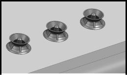


9 |

Bitte gut aufbewahren
Anleitungen für den Installateur
Alle Installations-, Regelungsund Umstellungsarbeiten auf eine andere Gasart müssen von einem autorisierten Fachmann und unter Beachtung der jeweils anwendbaren Regelungen und gesetzlichen Vorgaben sowie der Vorschriften der örtlichen Stromund Gasversorger vorgenommen werden.
Für Umstellungsarbeiten auf eine andere Gasart empfehlen wir, den Kundendienst zu rufen.
WICHTIG: Vor Beginn aller Arbeiten, die Gas und Stromzufuhr zum Gerät unterbrechen.
Vor dem Anschluss des Geräts an die Installation muss überprüft werden, ob das Gerät für den zugeleiteten Gastyp geeignet ist (siehe Tabelle I).
Unsere Kochfelder sind werkseitig für den Betrieb mit dem auf dem Typenschild angegebenen Gastyp eingestellt.
Der Ort, an dem das Gerät installiert werden soll, muss über die vorschriftsmäßige Belüftung verfügen. Daher müssen die Verbrennungsgase ins Freie ausgeleitet werden.
Die Abmessungen des Kochfelds sowie die Abmessungen der im Möbel anzufertigenden Öffnung überprüfen.
Die Arbeitsplatte muss eben und waagerecht sein.
Auch mit dem Ausschnitt muss die Stabilität gewährleistet sein. Die Arbeitsplatte muss zur Wand hin gegen Feuchtigkeit abgedichtet werden.
Für die Installation über einem Backofen muss geprüft werden, dass dieser über eine Zwangsbelüftung verfügt. Ebenso müssen die Abmessungen anhand der Einbauanleitung überprüft werden.
Die Platten auf der Arbeitsfläche in der direkten Umgebung des Kochfelds müssen aus nicht brennbarem Material bestehen.
Verkleidungen aus Schichtwerkstoffen sowie deren Verbindungsleim müssen hitzebeständig sein, um eine Abnutzung zu vermeiden.
Die elektrischen Leitungen dürfen keine Berührung zu den Hitzebereichen haben.
Die Stromnetzleitung muss am Möbel befestigt werden, damit es keine heißen Teile des Ofens oder des Kochfelds berühren kann.
Geräte mit elektrischen Bauteilen müssen vorschriftsgemäß mit der Erdableitung verbunden werden .
Das Gerät während der Installation vorsichtig behandeln. Keine Schläge auf das Gerät ausführen. Dieses Gerät ist nach dem allgemein gültigen Vorschriften und nur an einem gut belüfteten Platz zu installieren. Lesen Sie die Gebrauchsund Montageanleitung bevor Sie das Gerät installieren und gebrauchen.
WERDEN DIE DIESBEZÜGLICHEN BESTIMMUNGEN NICHT EINGEHALTEN, LIEGT DIE HAFTUNG BEIM INSTALLATEUR UND DER HERSTELLER IST VON DER HAFTUNG AUSGENOMMEN.
Einbau des Kochfelds im Küchenmöbel
Die Möglichkeit zum Einbau des Kochfelds in das Möbel entspricht gemäß der Norm für Gasgeräte EN 30-1-1 der Klasse 3.
Die Holzfasern, die zur Herstellung der Tischplattenmöbel verwendet werden, quellen im Kontakt mit Feuchtigkeit relativ schnell auf.
Daher sollten die Schnittflächen mit einem Spezialleim behandelt werden, um diese Flächen vor Dampf und Kondenswasser, das sich unter der Arbeitsplatte des Küchenmöbels bilden könnte, zu schützen.
de
Je nach Modell sind die Klammern und Dichtungen (Unterrand des Kochfelds) bereits montiert. Diese dürfen dann keinesfalls abgenommen werden.
Die Dichtung gewährleistet die Abdichtung der gesamten Arbeitsfläche und verhindert das Eindringen von Flüssigkeiten.
Ist die Dichtung werkseitig nicht montiert, die Roste, die Deckel der Brenner und die Verteiler Ihres Kochfelds abnehmen und das Kochfeld umdrehen. Die mit dem Gerät mitgelieferte selbstklebende Dichtung am unteren Rand des Kochfelds anbringen. Abb. 2.
Die Klammern aus dem beiliegenden Zubehörbeutel nehmen und an den dafür vorgesehenen unteren Stellen anschrauben. Abb. 2a.
Verfügt, müssen Sie nach Einsetzen des Kochfelds die Klammer drehen und kräftig anziehen, wie dies in Abb. 2b. beschrieben wird. Bei einem erforderlichen Ausbau die Klammer abschrauben und umgekehrt vorgehen.
A. Normale Einbauform
1-Mindestabstände (mm). In der Arbeitsplatte einen Ausschnitt mit den erforderlichen Abmessungen ausführen. Abb. 1a.
Wenn kein Ofen unter der Kochplatte montiert wird, sollte unterhalb der Kochplatte eine Trennplatte eingefügt werden, der den Zugriff von unten auf die Kochplatte verhindert. Das Kochfeld in seiner Einbauöffnung im Möbel zentrieren.
B. Versenkte Einbauform
Wichtiger Hinweis:
Alle Ausschnittarbeiten an der Arbeitsplatte sind in einer Fachwerkstatt durchzuführen.
Der Ausschnitt muss sauber und genau ausgeführt sein, da die Schnittkante an der Oberfläche sichtbar ist. Die Stabilität der betroffenen Möbel muß auch nach den Ausschnittarbeiten gewährleistet sein.
Verwenden Sie nur spezielle temeperaturund wasserfeste Arbeitsplatten (z. B. Naturstein oder geflieste Arbeitsplatte). Ausschnittmaße siehe Zeichnung. Abb. 1b.
Einbaumöbel müssen bis 90ºC temperaturbeständig sein. Bei gefliesten Arbeitsplatten: Die Auflageflächen bei Bedarf mit temperatur - und wasserfesten Leisten umlaufend erhöhen. Abb 3.
Kochfeld waagerecht in den Ausschnitt setzen und ausrichten, dabei auf gleichmäßigen umlaufenden Spalt achten. Das Kochfeld soll leicht unter der Arbeitsfläche liegen.
1- Geräte auf Funktion und Lage überprüfen.
2- Spalt zwischen Arbeitsplatte und Kochfeld mit geeignetem handelsüblichen Silikonkleber in Farbe Ihrer Wahl verfugen. Abb. 3b.
Achtung! Bei Naturstein-Arbeitsplatten kann es bei Verwendung ungeeigneter Silikonkleber zu nicht mehr entfernbaren Verfärbungen kommen. Ein geeigneter Kleber ist auch über unseren Kundendienst zu beziehen. Beachten Sie hierzu die Verarbeitungshinweise des Herstellers. Silikonkleber in die Fugen einspritzen.
Vor der Hautbildung Silikonkleber mit einem mit Seifenlösung angefeuchtetem Rakel oder Finger glätten.
Gerät erst nach dem Aushärten des Silikonklebers in Betrieb nehmen.

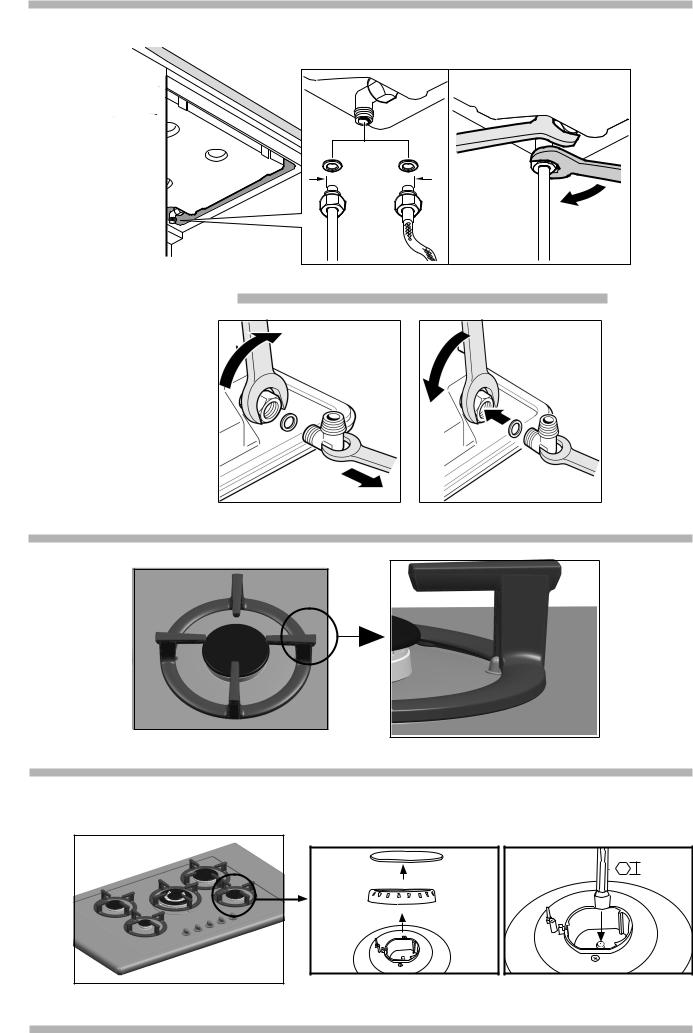
Anschluss der Kochfelder
3-Das Ende des Sammlers in der Zuleitung zum Gaskochfeld ist mit einem 1/2'' (20,955 mm) Gewindebogenstück ausgestattet, Abb. 4. Dieses Bogenstück erlaubt:
-den Anschluss mit einem Rohrstuck.
-Den Anschluss mit einem Schlauch aus Metall
(L min. 1 m - max. 3 m). In diesem Fall ist zu vermeiden, dass dieser Schlauch in Kontakt zu den beweglichen Teilen der Einbaueinheit gelangt (z. B. zu einer Schublade), und er darf nicht durch Öffnungen verlegt werden, die verschlossen werden könnten.
Bei allen Anschlussarten darf das Bogenstück in seiner werkseitigen Position weder bewegt noch verdreht werden. Bei der Benutzung dieses Geräts in Frankreich muss das werkseitig eingebaute Bogenstück ausgebaut, und durch das im Zubehörbeutel gelieferte Teil ersetzt werden, Abb 4 a, dabei nicht vergessen, auch die Dichtung einzusetzen.
Wird das Bogenstück aus irgendeinem Grund verdreht, muss die Dichtheit in diesem Bereich gewährleistet sein. Überprüfen Sie die Dichtheit aller durchgeführter Anschlüsse. Der Hersteller haftet nicht für Undichtheiten, wenn das Bogenstück bewegt oder verdreht wird, und auch nicht für die vom Installateur ausgeführten Anschlüsse.
4-Auf dem Typenschild muss die Spannung und die Gesamtleistung verglichen werden.
Das Gerät muss an die Erdableitung angeschlossen sein. Achten Sie darauf, dass der Anschluss entsprechend der gesetzlichen Vorschriften Ihres Landes ausgeführt worden ist. Die Bestimmungen der örtlichen Stromversorgungsgesellschaft müssen strikt eingehalten werden.
Zur Erfüllung der normalen Sicherheitsvorschriften muss seitens des Installateurs ein allpoliger Trennschalter mit einer Kontaktöffnung von mindestens 3 mm vorgesehen werden. Bei einem Anschluss durch eine für den Benutzer zugängliche Steckverbindung ist dies nicht erforderlich.
Mit Steckern ausgestattete Geräte dürfen nur an ordnungsgemäß installierte Steckdosen mit Erdableitung angeschlossen werden.
Das Gerät entspricht der Klasse “Y”, d. h., das Versorgungsstromkabel darf NICHT VOM BENUTZER sondern nur vom Kundendienst der Marke ausgewechselt werden. Der Querschnitt und die Art der Leitung darf nicht verändert werden.
Nehmen Sie keine Arbeiten im Innern des Gerätes vor. Wenden Sie sich ggf. an unseren Kundendienst.
Die Kochfelder werden mit einem Netzkabel mit oder ohne
Stecker geliefert. |
|
KABELARTEN: |
|
Kochplatte: |
Netzkabel: |
Alle Gase |
3 x 0.5 mm2 |
5-Zur Beendigung der Installation müssen die Verteiler und der Deckel der Brenner auf den entsprechenden Kochstellen angebracht werden. Außerdem müssen die Roste in ihren Halteelementen eingesetzt werden. Abb. 5.
Umstellung auf eine andere Gasart
Alle Installations-, Regelungsund Umstellungsarbeiten auf eine andere Gasart müssen von einem autorisierten Fachmann und unter Beachtung der jeweils anwendbaren Regelungen und gesetzlichen Vorgaben sowie der Vorschriften der örtlichen Stromund Gasversorger vorgenommen werden.
de
Für Umstellungsarbeiten auf eine andere Gasart empfehlen wir, den Kundendienst zu rufen.
WICHTIG: Vor Beginn aller Arbeiten, die Gasund Stromzufuhr zum Gerät unterbrechen.
Vor dem Anschluss des Geräts an die Installation muss überprüft werden, ob das Gerät für den zugeleiteten Gastyp geeignet ist.
Unsere Kochfelder sind werkseitig für den Betrieb mit dem auf dem Typenschild angegebenen Gastyp eingestellt. Wenn dies entsprechend der gültigen Vorschriften Ihres Landes zulässig ist (siehe Typenschild), kann dieses Kochfeld auf den Betrieb mit einer anderen Gasart umgestellt werden. Dazu sind folgende Maßnahmen erforderlich:
A ) Auswechseln der Brennerköpfe des Kochfelds 1 -Die Roste, Deckel und Brennerkörper abnehmen.
2 -Die Düsen mit einem 7 mm. Steckschlüssel (siehe Tabelle II) auswechseln und fest anziehen, damit deren Dichtheit gewährleistet ist. Abb. 6.
Bei diesen Brennern ist keine Einstellung der Primärluft erforderlich.
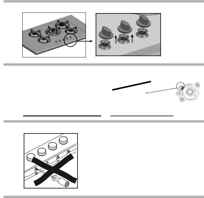
B)Einstellung des geringen Verbrauchs der Brennerhähne des Kochfelds.
1- Die Hähne auf die Position für den niedrigsten Verbrauch stellen.
2- Die Schaltelemente von den Hähnen abnehmen. Abb. 7. 3- Es wird ein innerer Dichtring aus flexiblem Gummi sichtbar. Dieser muss lediglich mit der Spitze eines Schraubendrehers weggedrückt werden, bis die Regulierschraube für die Armatur erreichbar ist. Abb. 8.
Die Dichtung niemals ausbauen.
4- Einstellung der Bypass-Schraube.
Bei Propan-oder Butangas muss die Schraube ganz eingeschraubt sein.
Bei Erdgas die Schraube nach links bis auf den Korrekten Gasauslass des Brenners drehen, so dass wenn man den Brenner von der Position Max. auf Min. schaltet, der Brenner weder ausgeht noch ein Flammenrückschlag entsteht.
5- Zur Gewährleistung der elektrischen Dichtheit und Dichtheit gegen auslaufender Flüssigkeiten vom Kochfeld müssen alle Dichtungen eingesetzt werden.
6- Die Schalter wieder auf den Hähnen montieren.
Die Achse des Hahns niemals ausbauen (Abb. 9): bei einer Störung den kompletten Hahn ersetzen.
C)Die Etikette mit dem Hinweis der Gasart, auf die das Gerät umgestellt wurde, an einer Stelle in der Nähe des Typenschilds anbringen.

Please detach and keep
Instructions for the installer
All installation, regulation and adaptation to other types of gas must be carried out by an authorised installation technician, respecting all applicable regulations, standards and the country's electrical and gas supply companies' specifications. It is recommended that you call our Technical Assistance Service for adaptation to other types of gas.
IMPORTANT: Cut the gas and electricity supplies to the appliance before any kind of work is performed.
Before connecting the appliance to the supply, check that it is prepared for the type of gas in question (see table I). Our hobs leave the factory set for the gas type indicated on the characteristics plate.
This appliance must be installed in a place with the proper level of ventilation. The gases produced during combustion must be released to the outside.
Check the size of the hob and the size of the opening to be made on the kitchen unit.
The work surface must be level and horizontal. The stability of the work surface must still be guaranteed after the cut-out has been made. The work surface must be sealed with the wall to protect against damp.
If it is to be installed over an oven, you must check that the oven is suffiently well ventilated and check the dimensions as given in the installation manual.
The panelling on the work surface in the immediate vicinity of the hob must be made of non-flammable material. Both stratified coatings and the adhesive used to fix them in place must be heat resistant. Otherwise, they may be damaged. Electric wiring must not come into contact with hot areas. The mains supply cable must be fixed to the kitchen unit to prevent it from coming into contact with hot parts on the oven or hob.
Appliances with electric components must be earthed. Handle the appliance with care throughout the entire installation process. Avoid knocking the appliance. This appliance shall be installed in accordance with the
regulations in force and only used in a well ventilated location. Read the instructions before installing or using this appliance.
SHOULD THE RELEVANT CONDITIONS NOT BE PROPERLY SATISFIED, THE INSTALLER, AND NOT THE MANUFACTURER, SHALL HELD LIABLE.
Installing the hob in the kitchen unit
The positioning of a hob in a kitchen unit is Class 3 according to the standard for gas appliances EN 30-1-1.
The wood fibres used in the manufacture of kitchen work surfaces are liable to swell when they come into contact with moisture. You are recommended, therefore, to coat cut edges with a special adhesive to protect them from steam or condensed water which could deposit beneath the work surface on the kitchen unit.
Depending on the model purchased, the fixtures and the watertight seal (lower edge of the hob) may come factory-fitted.
If this is the case, do not under any circumstances remove them. The seal keeps the entire work surface watertight and prevents leakage.
If these parts are not factory-fitted, fix the selfadhesive seal supplied with the appliance to the lower edge of the hob, Fig. 2.
Remove the clips from the attached accessories bag and screw them into the lower points designed for this purpose, Fig. 2a.
en
Once the hob is fitted you should turn the clip and tighten the screw as shown in Fig. 2b. For disassembly, unscrew the clip and proceed in the reverse manner.
A- Normal installation method
1-Minimum Distances (mm). Cut a hole of the necessary size in the work surface, Fig. 1a.
If the oven is not installed under the hob, place a separator to prevent access to the lower part of the hob.
If the cooking hob is to be installed above an oven, check that the oven is fitted with power ventilation, and check the dimensions according to the assembly manual.
Centre the hob in the hole on the work surface.
B- Flush installation method
Important note:
All cut-outs in the work surface are to be carried out at a specialist workshop.
The cut must be clean and precise, since the cut edge is visible on the surface. The stability of furniture being worked on must be ensured following the cut-outs.
Use special heat and water-resistant work surface (e.g. natural stone or tiled work surfaces).
See the diagram for the cutting dimensions. Fig. 1b.
The units into which the cooker is fitted must be heatresistant up to 90 ºC.
On tiled worktops:
If necessary, raise the height of the surfaces by fitting heat and water-resistant strips all the way round. Fig. 3.
Place the hob horizontally into the cut-out and align it, ensuring that the join is even on all sides Fig. 3a. The hob should be positioned just below the work surface.
1 - Check the function and location of the appliances.
2 - Fill in the gap between the worktop and the hob using a suitable commercial silicone bonding agent in a colour of your choice.
Caution. Use of unsuitable silicone bonding agents on natural stone worktops can cause permanent discoloration. Suitable bonding agents can be obtained from our after-sales service, cod. 310818.
Please observe the manufacturer´s instructions for use. Apply the silicone bonding agent in the joints.
Before the silicone bonding agent starts to form a skin, moisten a blade or your finger with a soapy solution and smooth it over.
The hob should only be used once the silicone bonding agent has hardened.
Hotplates connection
3 -The end of the input collector on gas hobs comes with a 1/2” (20,955 mm) threaded L-tube, Fig. 4. This caters for:
-Rigid connection.
-Connection to a flexible metal tube (L min. 1 m - max. 3 m). If this method is used, avoid both contact between this tube and moving parts on the housing (e.g. drawers) and passing the tube through spaces liable to get blocked.
In either of the cases, do not move or twist the L-tube from its factory-set position.
To use this appliance in France, it is necessary to remove the L-tube mounted in the factory and assemble the one supplied in the accessory bag. Fig. 4a. Do not forget to insert the seal. If, for some reason, the L-tube should be twisted, it is necessary to make sure that this area is properly sealed. Make sure that all connections performed are free of leakage.

en
The manufacturer does not accept any liability for leakage on connections performed by the installer or if the L-tube is moved or twisted.
4 -Check the voltage and total power on the characteristics plate. The appliance must be EARTHED.
Make sure that connection has been performed in accordance with legal regulations in force for the country in question. Comply fully with the conditions laid down by the local electricity company.
In order to meet normal safety standards, the installer must supply an all-pole circuit breaker with a contact aperture of at least 3 mm. This is not necessary when connection is made via a socket, so long as this is accessible to the user. Appliances equipped with plugs should only be connected to sockets which are duly earthed.
The appliance is type "Y". This means that the input supply cable cannot be changed by the user. Only the brand's service technicians are qualified to replace this cable. Use the right cable type and section.
Do not tamper inside the appliance. If necessary, call our Service Centre.
Hobs with control knobs are supplied with a plugged or unplugged power cable.
TYPES OF CABLE
Hob: |
Power cable: |
All gas |
3 x 0.5 mm2 |
5 -In order to complete the installation process, you must place the diffusers and the tops of the burners on their corresponding burners. Also you must place the metal grids correctly on their supporting elements. Fig. 5.
For Natural Gas: turn the screw in an anticlockwise direction until the correct release of gas is reached:
when the burner is changed from the maximum to minimum settings, the flame does not go out or backfire.
5 - Re-assembling the anti-liquid seals. All the seals must b system against the spillage of liquids on the hob.
6 - Re-assemble the control knobs. Never dismount the valve shaft (fig. 9): in the event of damage, change the entire valve.
C) Put the label which indicates the type of gas the appliance has been adapted to near the characteristics plate.
Changing the type of gas
All installation, regulation and adaptation to other types of gas must be carried out by an authorised installation technician, respecting all applicable regulations, standards and the country's electrical and gas supply companies' specifications. It is recommended that you call our Technical Assistance Service for adaptation to other types of gas.
IMPORTANT: Cut the gas and electricity supplies to the appliance before any kind of work is performed.
Before connecting the appliance to the supply, check that it is prepared for the type of gas in question. Our hobs leave the factory set for the gas type indicated on the characteristics plate.
Depending on the regulations in force in your country, this hob may be adapted to work with other types of gas (see characteristics plate). To adapt the gas type, proceed as follows:
A ) Changing the injectors on the burners
1 -Remove the grates, covers and burner core.
2 -Change the injectors using a 7-mm socket wrench (see table II) and be sure to tighten them down properly so that they are fully air-tight. Fig. 6.
It is not necessary to adjust the primary air on these burners. B ) Adjusting reduced consumption on the burner valves.
1 - Set the valves to minimum.
2 - Remove the control knobs from the valve shafts. Fig. 7. 3 - It has a flexible rubber seal. Simply apply pressure with the tip of the screwdriver to release the thread toward the tap´s adjusting screw. Fig. 8.
Do not remove the disc seal.
4 -Adjusting the by pass screw.
For Propane and Butane Gas: the screw must be tightened down fully.
 Loading...