


EL-51245
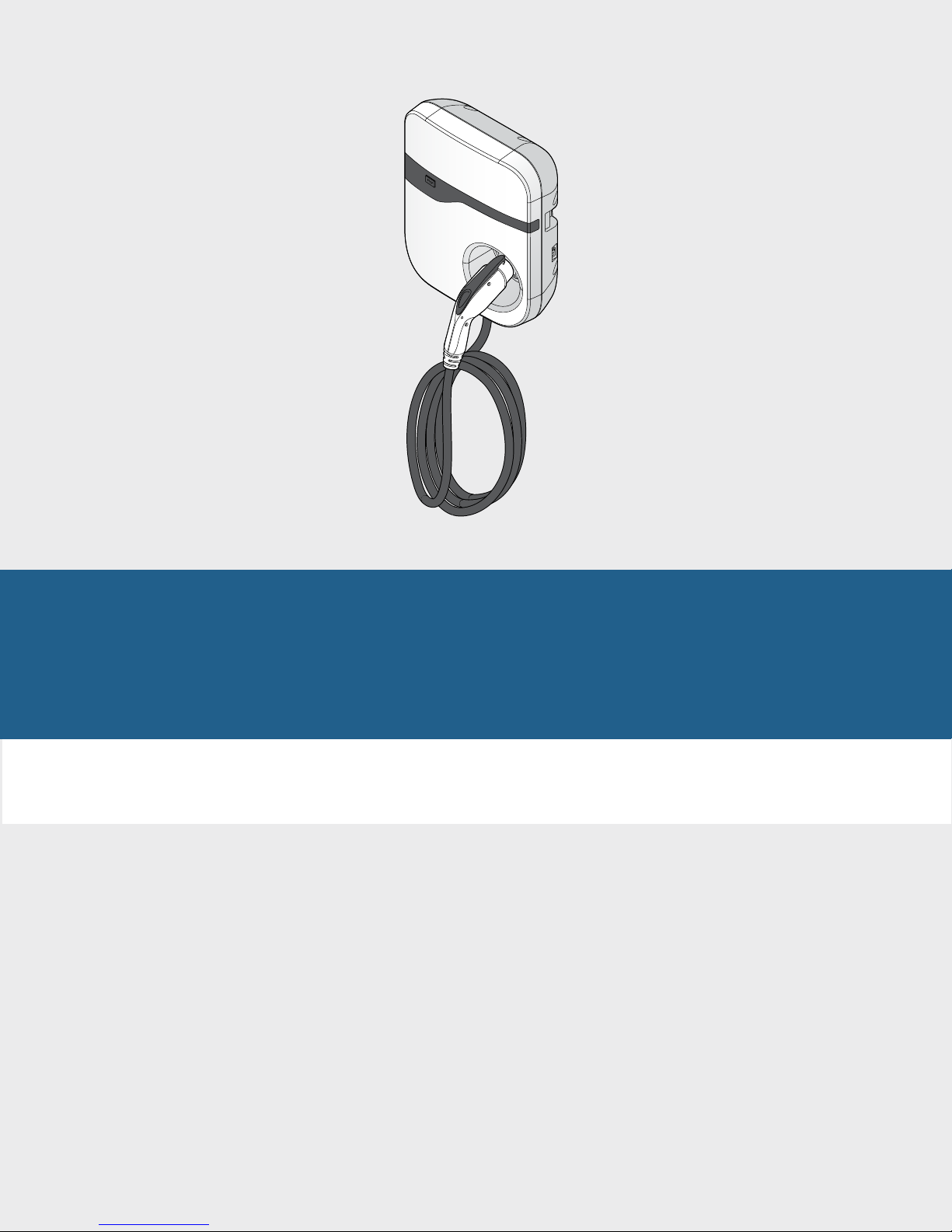
Power Max Level 2 Charging Station
en Installation and Operating Instructions
fr Guide d‘installation/Instructions d’emploi

en | 2 | Installation and Operating Instructions | Power Max Level 2 Charging Station
This equipment has been tested and found to comply with the limits for a Class B digital device, pursuant to part 15
of the FCC Rules. These limits are designed to provide reasonable protection against harmful interference in a residential installation. This equipment generates, uses and can radiate radio frequency energy and, if not installed and
used in accordance with the instructions, may cause harmful interference to radio communications. However, there
is no guarantee that interference will not occur in a particular installation. If this equipment does cause harmful interference to radio or television reception, which can be determined by turning the equipment off and on, the user
is encouraged to try to correct the interference by one or more of the following measures:
—Reorient or relocate the receiving antenna.
—Increase the separation between the equipment and receiver.
—Connect the equipment into an outlet on a circuit different from that to which the receiver is connected.
—Consult the dealer or an experienced radio/TV technician for help.
Cet équipement a été testé et déclaré conforme aux limites d’un appareil numérique de classe B, selon la partie 15
de la réglementation FCC. Ces limites sont conçues pour fournir une protection raisonnable contre les interférences
nuisibles dans une installation résidentielle. Cet équipement génère, utilise et peut émettre de l’énergie radioélectrique. Si l’installation et l’utilisation ne sont pas conformes aux instructions, il peut causer des interférences nuisibles aux communications radio. Toutefois, il n’existe aucune garantie qu’aucune interférence ne se produira dans
une installation particulière. Si cet équipement provoque des interférences nuisibles à la réception radio ou télévisu-
elle, ce qu’il est possible de vérier en éteignant et rallumant l’équipement, l’utilisateur doit tenter de corriger les
interférences à l’aide d’une ou plusieurs des mesures suivantes :
— Réorienter ou déplacer l’antenne de réception.
— Augmenter la distance entre l’équipement et le récepteur.
— Brancher l’équipement sur une prise d’un circuit différent de celui auquel le récepteur est branché.
— Consulter le concessionnaire ou un technicien radio/TV compétent pour obtenir de l’assistance.
Este equipo ha sido probado y se apega a los límites para los dispositivos digitales de Clase B, en virtud de la sección 15 de las Reglas de la Comisión Federal de Comunicaciones (FCC). Estos límites han sido diseñados para proporcionar una protección razonable contra interferencia perjudicial en una instalación residencial. Este equipo genera, usa y puede radiar energía de radiofrecuencia y si no se instala y utiliza conforme a las instrucciones, puede causar interferencias perjudiciales con las comunicaciones radiofónicas. No obstante, no existe ninguna garantía de que
no se produzcan interferencias en una instalación especíca. Si este equipo causa interferencias perjudiciales para
la recepción de radio o televisión, lo cual se puede determinar encendiendo y apagando el equipo, recomendamos
al usuario que intente corregir dichas interferencias con una o varias de las siguientes medidas:
—Reorientar o reubicar la antena receptora.
—Aumentar la separación entre el equipo y el receptor.
—Conectar el equipo a un enchufe o circuito diferentes de aquellos a los que el receptor estaba conectado.
—Consultar al distribuidor o a un técnico de radio/televisión con experiencia para obtener ayuda.
569217 | REV. D | 09.08.2016

Installation and Operating Instructions | Power Max Level 2 Charging Station | 3 | en
Contents English ............4
Sommaire Français .........19
569217 | REV. D | 09.08.2016

en | 4 | Installation and Operating Instructions | Power Max Level 2 Charging Station
Contents
1 Introduction 5
1.1 Applications 5
2 Important Safety Warnings and Instructions 5
3 FeaturesandSpecications 6
3.1 Front View 6
3.2 Package Contents 6
3.3 Specications 7
4 Installation 8
4.1 Important SAFETY WARNINGS and Instructions 8
4.2 Grounding Instructions 8
4.3 Recommended Tools 8
4.4 Installing the Power Max Level 2 Charging Station 9
5 Maintenance 12
6 OperationsandTroubleshooting 13
6.1 Charging 13
6.2 Charging Status Indicators 15
6.3 Troubleshooting 16
7 Important Notices 17
7.1 Limited Warranty 17
7.2 Disclaimer 17
7.3 Limitation of Liability 17
7.4 To Obtain Warranty Service 18
7.5 Technical Support 18
569217 | REV. D | 09.08.2016
Installation and Operating Instructions | Power Max Level 2 Charging Station | 5 | en
1 Introduction
The Power Max Level 2 Charging Station is designed for the North American market to charge plug-in electric vehicles (PHEV) and battery electric vehicles (BEV). It provides AC Level 2 Charging that effectively shortens charging
time for typical electric vehicles (EVs) when compared to the Level 1 Cordset.
1.1 Applications
} Residential
} Private and public parking facilities
} Fleet
} Shopping malls and retailers
} Workplace
Please read and follow these safety warnings and operating instructions carefully before operating the Power Max
Level 2 Charging Station. Failure to follow these instructions may result in serious injury or property damage.
2 Important Safety Warnings and Instructions
IMPORTANT SAFETY INSTRUCTIONS. SAVE THESE INSTRUCTIONS.
WARNING
DisconnectelectricalpowertothePowerMaxLevel2ChargingStationbeforeinstallation.Failuretodo
so may cause physical injury or damage to the electrical system and charging unit.
CAUTION
Toreducetheriskofre,connectonlytoacircuitprovidedwith20amperes(EL-51245-XXXXX)or40
amperes(EL-51253-XXXXX,EL-51254-XXXXX)maximumbranchcircuitovercurrentprotectionin
accordancewiththeNationalElectricalCode,ANSI/NFPA70.
} Read all the instructions before using this product.
} Children should be supervised when this product is used around children.
} Do not put ngers into the EV connector.
} Do not use this product if the EV cable is frayed, has broken insulation, or displays any other indication of
damage.
} Do not use this product if the enclosure or the EV connector is broken, cracked, open, or show any other
indication of damage.
} This product should be installed only by a qualied approved technician.
} Make sure that the materials used and the installation procedures follow local building codes and safety
standards.
} The information provided in this manual in no way exempts the user of responsibility to follow all applicable
codes or safety standards.
} Bosch and its partners are not responsible for physical injury, damage to property or equipment caused by the
installation of this product.
} This document provides instructions for the wall-mounted Power Max Level 2 Charging Station and should not be
used for any other product. Before installation or use of this product, you should review this manual carefully and
consult with a licensed contractor, licensed electrician, or trained installation expert to make sure of compliance
with local building codes and safety standards.
569217 | REV. D | 09.08.2016

en | 6 | Installation and Operating Instructions | Power Max Level 2 Charging Station
3 FeaturesandSpecications
3.1 Front View
3.2 Package Contents
} Power Max Level 2 Charging Station
} Installation and Operating Instructions
} Mounting bracket
} Three (3) Torx T30 screws
1. STOPbutton
2. Chargingplugandcable
} SAE J1772 compliant
3. Status indicator
} Ready (green LED on)
} Charging (green LED ashing)
} Fault (red LED on)
} Warning (red LED ashing)
4. ON/OFFswitch
5. Plugdock
569217 | REV. D | 09.08.2016
Installation and Operating Instructions | Power Max Level 2 Charging Station | 7 | en
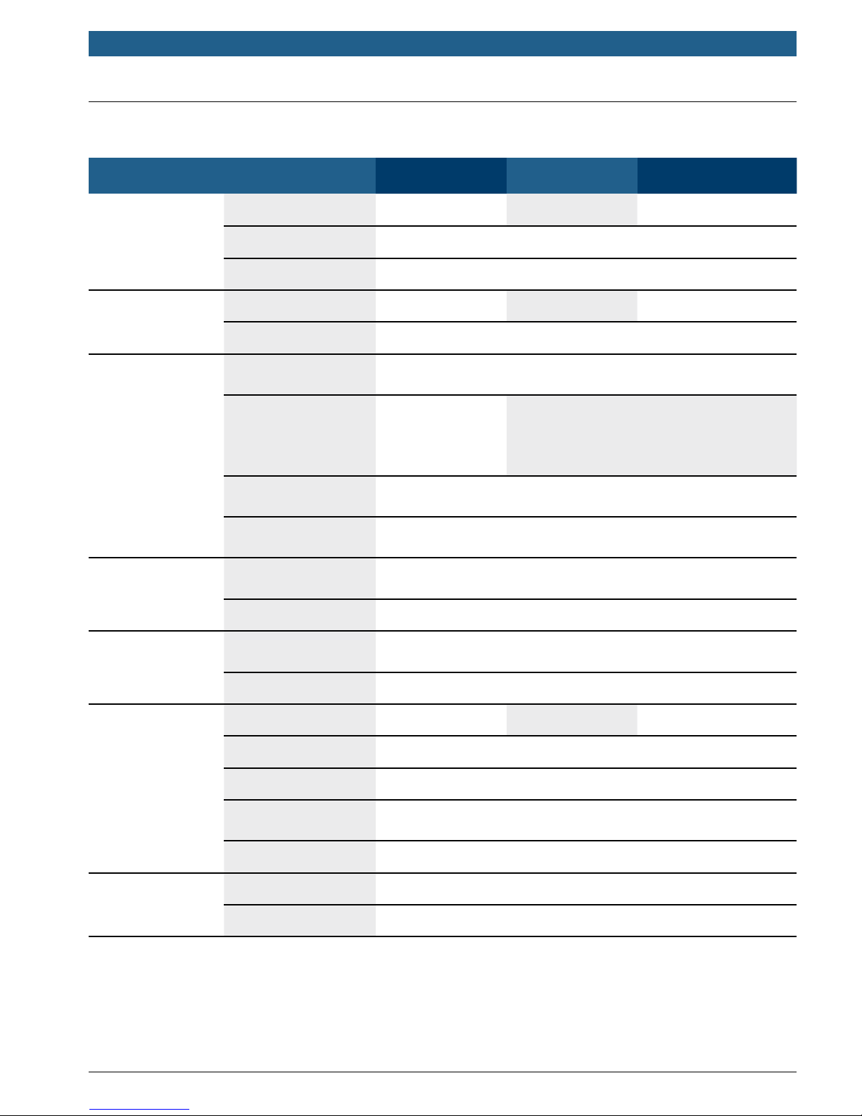
3.3 Specications
Model EL-51245-XXXXX EL-51253-XXXXX EL-51254-XXXXX
Input Rating 208-240 Vac, 16 A 208-240 Vac, 30 A 208-240 Vac, 30 A, 60 Hz
Power Input
Power Output
Protection
User Interface &
Control
Environmental
Connections & Wiring L1, L2, and Ground, hardwired w/ terminal block
Standby Power < 5 W
Output Rating 208-240 Vac, 16 A 208-240 Vac, 30 A 208-240 Vac, 30 A
Cold-Load Pickup Randomized delay before charge resume after power failure
Internal Residual
Current Detection
20 mA CCID per UL 2231
2-pole 20 A
Upstream Breaker
breaker on dedi-
cated circuit,
2-pole 40 A breaker on dedicated circuit,
non-GFCI type
non-GFCI type
Output Protection
Electrical Protection
Status Indicators
Power output is terminated upon detection of charging connector
plug-out
Over current, short circuit, over voltage, under voltage, ground
fault, surge protection, over temperature
Standby (solid green), charging (ashing green), fault (solid red),
warning (ashing red)
Buttons/Switches ON/OFF switch, stop button
Operating
Temperature
-22oF to +122oF (-30oC to +50oC)
Humidity 95% relative humidity, non-condensing
Charging Cable Length 12/18/25-ft cable 18-ft cable 25-ft cable
Ingress Protection Type 3R
Mechanical
Mounting Type Wall-Mount
Dimension (W x H x D)
Net Weight 15.4 lb (7 kg)
Certicate UL, cUL
Regulation
Charging Interface SAE J1772 compliant charging plug
13.8 x 15.7 x 5.0 inch (350 x 400 x 126 mm), excluding charging
cable and support bracket
569217 | REV. D | 09.08.2016

en | 8 | Installation and Operating Instructions | Power Max Level 2 Charging Station
4 Installation
4.1 Important SAFETY WARNINGS and Instructions
IMPORTANT SAFETY INSTRUCTIONS. SAVE THESE INSTRUCTIONS.
WARNING
Dangerofelectricalshockorinjury.TurnOFFpoweratthepanelboardorloadcenterbeforeworking
inside the equipment or removing any component. Do not remove circuit protective devices or any
othercomponentuntilthepoweristurnedOFF.
The Power Max Level 2 Charging Station should be installed only by a licensed contractor, and/or a licensed
electrician or trained installation expert in accordance with all applicable state, local and national electrical codes
and standards.
Before installing the Power Max Level 2 Charging Station, review this manual carefully and consult with a licensed
contractor, licensed electrician, or trained installation expert to ensure compliance with local building practices,
climate conditions, safety standards, and state and local codes.
The Power Max Level 2 Charging Station is to be hardwired only. The installation of a plug is not allowed.
4.2 Grounding Instructions
This product must be connected to a grounded, metal, permanent wiring system; or an equipment grounding conductor must be run with the circuit conductors and connected to the equipment grounding terminal or lead on the
product.
4.3 Recommended Tools
The following tools are recommended for the Power Max Level 2 Charging Station installation:
} Supplied accessories and components:
– Level 2 Charging Station mounting bracket
– Three (3) Torx T30 screws for securing the Level 2 Charging Station to the mounting bracket
} Installer-supplied components:
– Conduit of appropriate trade size for power wire
– Two (2) screws for securing the main body mounting bracket to the wall
} Recommended tools:
– Torx T30 screwdriver
569217 | REV. D | 09.08.2016
Installation and Operating Instructions | Power Max Level 2 Charging Station | 9 | en
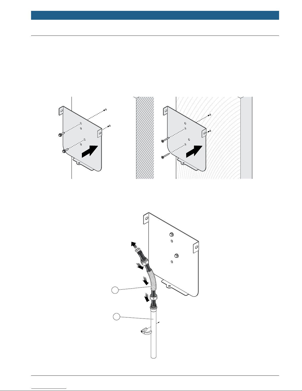
4.4 Installing the Power Max Level 2 Charging Station
1. See Figure 4-1. Secure the Level 2 Charging Station mounting bracket to the wall using appropriate screws and
bracket holes, as shown in Figure 4-1. Thread 1/4-in. expansion bolts through bracket offset holes into masonry
walls as shown and torque to 78 lb·in (8.8 N·m). Thread 2-in., or longer, No. 8 wood screws through bracket
inline holes into nished walls supported by wood studs and torque to 26 lb·in (3 N·m).
Note:
The Level 2 Charging Station must be mounted at a sufcient height from grade such that the height of the plug
dock is located between 24–48 in. (0.6–1.2 m) from grade per NEC Article 625.
Figure 4-1. Mounting bracket use on masonry wall (left) and nished wall (right)
2. See Figure 4-2. Choose appropriate conduit in accordance with all applicable state, local, and national electrical
codes and standards. Use exible conduit when connecting to the rear of the Level 2 Charging station to
faciliate rotation and installation on mounting bracket (Figure 4-4).
1
2
1. Flexibleconduit
2. Rigid conduit
Figure 4-2. Conduit use
569217 | REV. D | 09.08.2016
en | 10 | Installation and Operating Instructions | Power Max Level 2 Charging Station
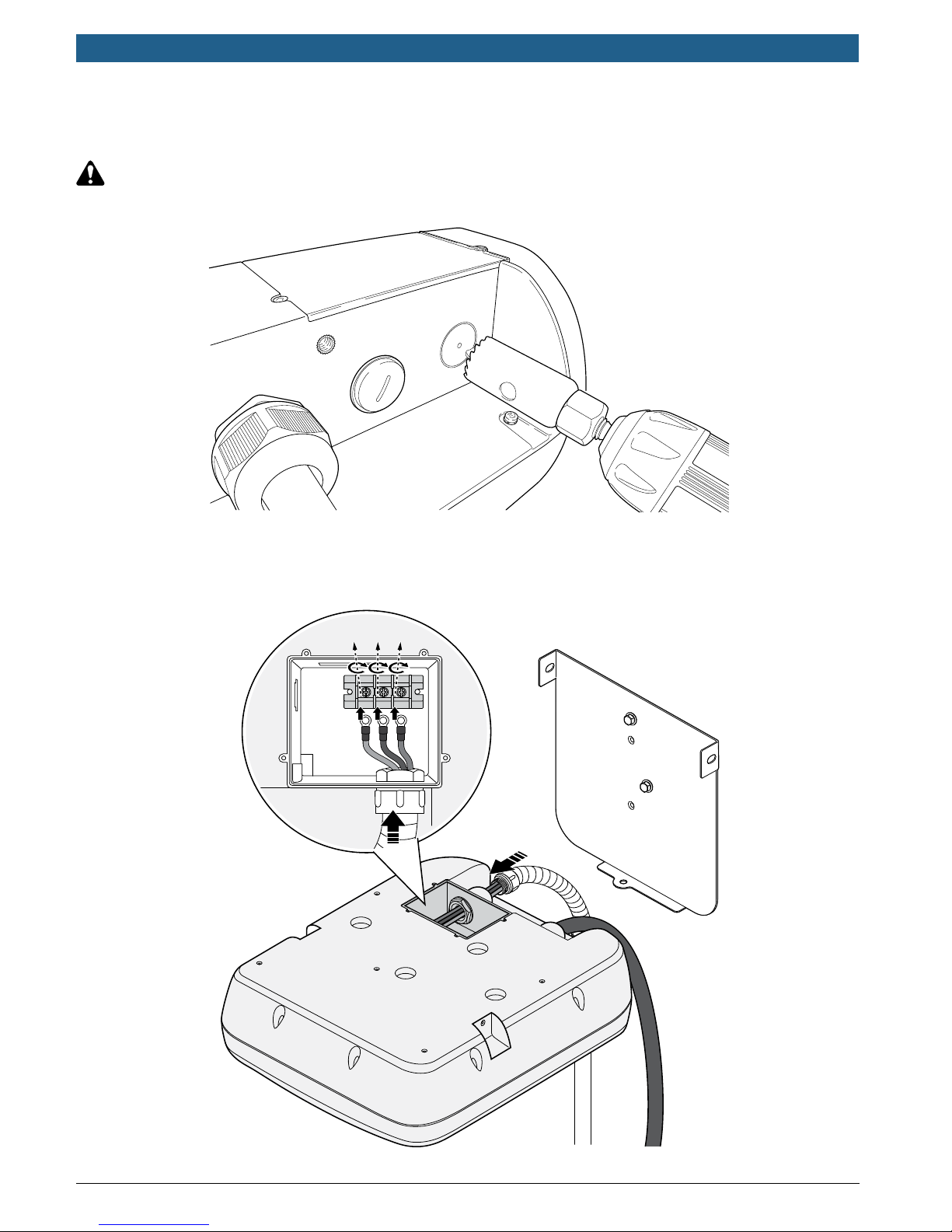
G L2 L1
3. See Figure 4-3. Drill a hole of an appropriate size to accommodate the conduit system tting in the bottom of
the plastic housing as shown.
CAUTION
Drill the hole carefully to avoid punching through the housing and damaging internal components
Place the Level 2 Charging Station on a soft surface during drilling to avoid damage.
Figure 4-3. Drilling hole for conduit
4. See Figure 4-4. Install ring terminal eyelets on each wire end and connect each to the correct terminal input
block connector. Use copper wire of the appropriate size to operate the EVSE at its rated amperage output.
Replace the compartment cover and torque to 4.6 lb·in (0.5 N·m).
Figure 4-4. Electrical wiring with detail of input terminal block
569217 | REV. D | 09.08.2016
Installation and Operating Instructions | Power Max Level 2 Charging Station | 11 | en
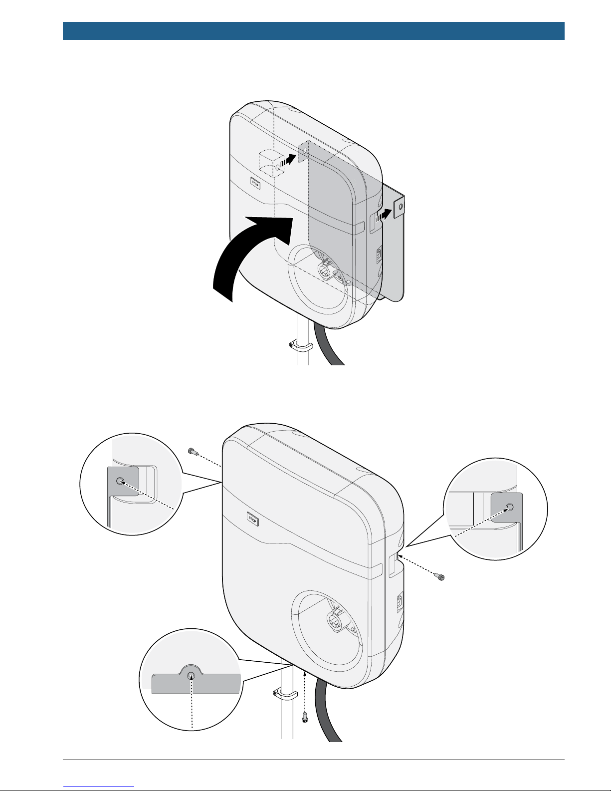
5. See Figure 4-5. Align the screw holes of the mounting bracket with the Level 2 Charging Station.
Figure 4-5. Alignment of charging station on mounting bracket
6. See Figure 4-6. Install and secure the charging station to the mounting bracket with the three (3) screws
supplied.
Figure 4-6. Installation screw locations
569217 | REV. D | 09.08.2016
 Loading...