Bosch F.01U.512.626 Datasheet

Communications Systems | LBB 1990/00 Plena Voice Alarm Controller
LBB 1990/00 Plena Voice Alarm
Controller
Heart of the Plena Voice Alarm SystemSix-zone system controller
Built-in 240 W amplifier
12 business and emergency control inputsEN 54 16 and EN 60849 compliant
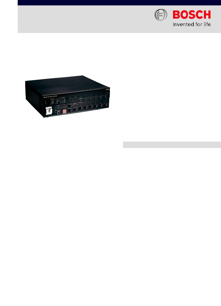
The Plena Voice Alarm Controller is the heart of the voice alarm system. It is the basis of the Plena Voice Alarm System, and has all the essential functionality for compliance with the EN 60849 and 54 16 standards, including full system supervision, loudspeaker line impedance supervision, a supervised emergency microphone on the front panel and a supervised message manager.
The messages can be merged to allow even more flexible use of pre-recorded announcements and evacuation messages. The controller can be used as a stand-alone system with up to six zones, or expanded to up to
60 zones using additional six-zone routers. Up to eight call stations can be connected. Interconnections are made using standard RJ45 connectors and shielded CAT-5 cable.
A built-in 240 W amplifier provides the power for the emergency call channel and BGM. Additional Plena Amplifiers can be added to provide two-channel operation. All amplifiers are supervised. The audio output uses standard analog audio 100 V line switching for full compatibility with the Plena family of public address equipment and Bosch EVAC-compliant loudspeakers. The system is configured using DIP switches for basic functionality and a PC for more advanced functions.
Functions
The controller has two BGM source inputs and a mic/line input with configurable priority, speech filter, phantom power and selectable VOX activation. A total of 16 priority levels can be specified for microphone, call stations and trigger inputs for optimum system flexibility.
The powerful 240 W output section has six transformerisolated 100 V constant-voltage outputs for driving 100 V loudspeakers in six separate zones. The 100 V-technique reduces line losses on longer distances and provides easy parallel connection of multiple loudspeakers. All zones may be individually selected from the front panel, and the BGM output level in each zone can be individually set in six steps. The controller supports A/B wiring.
Configuration software is provided on the CD included with the unit. The CD also includes many useful programs, such as MP3-ripping software, a sample-rate converter, various audio and visual tools, and free, MP3-coded music.
www.boschsecurity.com

2 | LBB 1990/00 Plena Voice Alarm Controller
The amplifier output is also available as a separate output on 100 V and 70 V. A separate 100 V call-only output provides addressing for an area where BGM is not required but where priority announcements are. Six configurable volume-override output contacts are available for overriding local volume controls during priority calls. Both four-wire and three-wire schemes are supported. An LED meter monitors the output.
Up to 255 messages can be stored in the internal 16 MB flash ROM, without a need for battery backup. Each message can have any length within the total available capacity. Messages and configurations are uploaded from a PC via USB 2 into the memory, after which the unit operates without a PC connection. The standard WAVformat is used for the messages, and sample rates of
8 kHz up to 24 kHz with 16-bit word length (linear PCM) are supported. This gives up to 17 minutes of recording time with CD-quality signal-to-noise ratio.
The unit has 12 contact trigger inputs for business and emergency (EMG) calls. Each can be configured for a message consisting of a sequence of up to eight wave files. In this way some wave files may be used in various combinations with other messages, optimizing flexibility and the amount of storage space used . Multiple messages can be merged to form one integrated message. A zone selection, together with this sequence can be configured for each trigger input.
Controls and indicators Front
•LED power meter
•13 system fault LEDs
•Two fault state buttons
•Two emergency state buttons
•Six EMG zone status LED pairs
•Six EMG zone select buttons
•Six BGM zone select LEDs
•Six BGM zone select buttons
•Six BGM zone volume control knobs
•Two BGM source status LEDs
•Three knobs for BGM volume, treble, and bass levels
•All-call button
•Indicator test button
•EMG state button
•Alert message button
Back
•Three service settings DIP switches
•Calibration switch
•Four system configuration DIP switches
•Mains voltage selector
•Power switch
•Power cord socket
•Mic/line level switch
•Three DIP switches for VOX, speech, phantom power
•Microphone volume control knob
•Digital message volume control screw
•Monitoring speaker volume control knob
Interconnections
Front
•Microphone socket
Back
•12 loudspeaker outputs
•External amplifier input
•Amplifier output (on 100 V)
•Backup power input
•Call output
•Six volume override outputs
•Three status outputs
•12 trigger inputs
•24 VDC output
•Two call station connectors (redundant)
•USB 2 connector
•Two DE-9 connectors (reserved)
•External amplifier output
•Line output connectors
•Two BGM inputs
•PC call station input (reserved)
•Two RC station connectors (redundant)
•Connector to LBB 1992/00 (router)
Certifications and Approvals
Region |
Certification |
|
Europe |
CE |
TUV certificate IEC60849 |
|
|
Declaration of Conformity |
|
TUEV- |
|
|
SUED |
|
Poland |
CNBOP |
|
Safety |
acc. to EN 60065 |
Immunity |
acc. to EN 55103-2 |
Emission |
acc. to EN 55103-1 |
Emergency |
acc. to EN 54 16 / EN 60849 |
Installation/Configuration Notes
LBB 1990/00 rear view
 Loading...