


BOSCH EB612PB90E, PBH615B80E, PBP615B80E, PBP612B80E, PBP616B80E User Manual [fr]
...
9000512208 9000512208 F |
|
|
|
|
|
|
|
|
|
|
|
Ú Installation instructions |
Û Instrucciones de montaje |
||
Ø Montageanleitung |
ì Instruções de montagem |
||
Þ Notice de montage |
é Installatievoorschrift |
||
â Istruzioni per il montaggio |
|
|
|
|
|
|
|
|
|
|
|
1 |
|
|
min. 100 |
510 |
min. 600 |
|
|
480÷490± 20 |
560± 20 |
min. 50 |
|
580 |
|
min. 650 min. 450
min. 5
2
3 |
3a |
4 |
4a |
5
6
7 |
7a |
8

en
Safety precautions
Read the appliance instructions before installing and using.
The graphics in these Assembly instructions are given as a guide only.
The manufacturer is exempt from all liability if this manual's requirements are not complied with.
All operations relating to installation, regulation and conversion to other gas types must be carried out by an authorised installation engineer, respecting all applicable regulations, standards and the specifications of the local gas and electricity providers.
You are recommended to contact the Technical Assistance Service to convert to another gas type.
Before you begin, turn off the appliance's electricity and gas supply.
This appliance has been designed for home use only, not for commercial or professional use. This appliance cannot be installed on yachts or in caravans. The warranty will only be valid if the appliance is used for the purpose for which it was designed.
Before installing, check that local distribution conditions (gas type and pressure) and the appliance's adjustment are compatible (see table I). The appliance's adjustment conditions are written on the label or the specifications plate.
This appliance can only be installed in a well-ventilated place in accordance with existing regulations and ventilation specifications. The appliance must not be connected to a combustion product removal device.
The supply cable must be attached to the unit to prevent it from touching hot parts of the oven or hob.
Appliances with electrical supply must be earthed.
Do not tamper with the appliance's interior. If necessary, call our Technical Assistance Service.
Before installing
This appliance is class 3 type, according to the EN 30-1-1 regulation for gas appliances: built-in appliance.
The units next to the appliance must be made of non-flammable materials. The laminated covering and glue for adhering it must be heat resistant.
This appliance cannot be installed above fridges, washing machines, dishwashers or similar.
An oven must have forced ventilation to install a hob above it. Check the dimensions of the oven in the installation manual.
If an extractor fan is installed, you must follow the installation manual's instructions, always keeping a minimum distance of 650 mm to the hob.
Preparation of the kitchen unit (fig. 1-2)
Make an appropriate size cut in the work surface.
If the hob is electric or mixed (gas and electricity) and there is no oven below, place a non-flammable separator (e.g. metal or plywood) 10 mm from the bottom of the hob. This will prevent access to the base of the hob.If the hob is gas, it is recommendable to place the separator at the same distance.
On wood work surfaces, varnish the cutting surfaces with a special glue. This protects them from moisture which could collect under the work surface.
Installation of appliance
Depending on the model, the adhesive seal may be factoryfitted. If this is the case, it should not be removed under any circumstances, since the adhesive seal prevents leaks. If the seal has not been factory-fitted, apply it to the underside of the hob. Fig. 3.
Fitting the appliance onto the kitchen unit:
1.Remove the clips from the accessory bag and screw them into the position indicated so that they can turn freely.
2.Insert and centre the hob.
Press the sides of the hob until it is supported around its entire perimeter.
3.Turn the clips and tighten them fully.
The position of the clips depends on how thick the work surface is. Fig. 3a.
Removal of hob
Turn off the appliance's electricity and gas supply.
Unscrew the clips and proceed in the reverse order to installation.
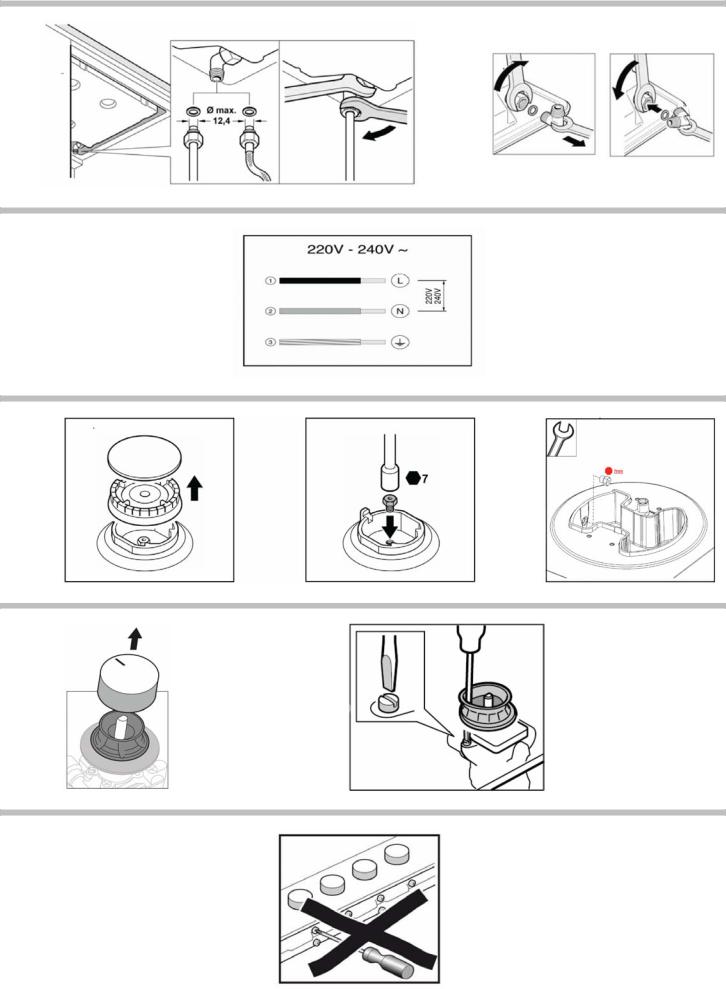
Gas connection (fig. 4)
The end of the inlet connection point of the gas hob has a 1/2” (20.955 mm) thread that allows for:
■fixed connection.
■connection using a flexible metal pipe (L min. 1 m - max. 3 m).
The watertight seal (034308) supplied must be inserted between the manifold outlet and the gas supply.
You must prevent the pipe from coming into contact with moving parts of the kitchen unit (for example, a drawer) and prevent access to any spaces which might become obstructed.
Do not move the L-tube from the factory-fitted position, regardless of the connection type.
France: substitute the factory-fitted L-tube for that included in the accessory bag. Fig. 4a.
Please remember to insert the seal.
ã=Danger of leaks!
If any connection is handled, check the seal.
The manufacturer is not liable for any connection leaking, after being handled.
Electric connection (fig. 5)
Check that the voltage and power of the appliance are compatible with the electrical installation.
The hobs are supplied with a power cable with or without a wall socket plug.
Provide an omnipolar cut-off switch with a minimum contact opening of 3 mm (except for plug connections, if the user has access to it).
Appliances with plugs must only be connected to sockets that have earth wires correctly installed.
This appliance is type “Y”: the supply cable can only be changed by the Technical Assistance Service and not the user. The cable type and minimum cross-section must be respected.
Changing the gas type
If the country's regulations allow, this appliance can be adapted to other types of gas (see specifications plate). The components required for this are in the transformation kit supplied (depending on the model) or are available from our Technical Assistance Service. The following steps should be taken:
A) Changing the nozzles (fig. 6):
1.Remove the pan supports, burner caps and diffusers.
2.Change the nozzles using the spanner provided by our Technical Assistance Service (code 340847 or 340808 for double-flame burners), see table II, taking special care to ensure that the nozzle does not fall when it is removed from or fitted to the burner.
Ensure that it is completely tightened in order to guarantee the seal.
Primary air adjustment is not necessary with these burners.
3.Position the diffusers and burner caps on the corresponding rings. The pan supports must also be positioned correctly.
B) Adjusting the taps
1.Set the control knobs to minimum.
2.Remove the control knobs from the taps. Fig. 7.
It has a flexible rubber valve reinforcing ring. Simply press on this seal with the tip of a screwdriver to allow access to the tap adjusting screw. Fig. 7a. Never remove the valve reinforcing ring.
3.Adjust the minimum ring setting by turning the by-pass screw using a flat head screwdriver.
Depending on the gas to which your appliance is going to be adapted, see table III, carry out the corresponding action:
A:firmly tighten the by-pass screws.
B:loosen the by-pass screws until the gas flow from the burners is correct: when adjusting the control knob between maximum and minimum, the burner does not go out, nor is there a flame backdraught created.
C:the by-pass screws need to be changed by an authorised engineer.
D:do not touch the by-pass screws.
If the by-pass screw cannot be accessed, disassemble the grease drip tray, which is fitted to the hob with a series of screws. The following steps must be taken to remove it:

1.Remove all pan supports, burner caps, diffusers and control knobs.
2.Remove the screws from the burners.
3.To reinstall the appliance, proceed in the reverse order to disassembly.
All valve reinforcing rings must be in position to ensure watertightness. These devices are essential for the correct operation of the appliance as they prevent liquids and dirt from entering the appliance.
Never remove the tap spindle (Fig. 8). In the event of a malfunction, change the whole tap.
Caution!
After finishing, the sticker indicating the new type of gas must be placed close to the specifications plate.
de
Sicherheitshinweise
Lesen Sie die Gebrauchsanweisung für das Gerät, bevor Sie es installieren und benutzen.
Die Abbildungen in dieser Anleitung dienen der Veranschaulichung.
Der Hersteller ist jeglicher Verantwortung enthoben, wenn die Bestimmungen dieses Handbuchs nicht eingehalten werden.
Alle Installations-, Regelungsund Umstellungsarbeiten auf eine andere Gasart müssen von einem autorisierten Fachmann und unter Beachtung der jeweils anwendbaren Regelungen und gesetzlichen Vorgaben sowie der Vorschriften der örtlichen Stromund Gasversorger vorgenommen werden.
Für Umstellungsarbeiten auf eine andere Gasart empfehlen wir, den Kundendienst zu rufen.
Stellen Sie vor der Durchführung jeglicher Arbeiten die Stromund Gaszufuhr ab.
Dieses Gerät wurde ausschließlich für die Verwendung in Privathaushalten entworfen; eine kommerzielle oder gewerbliche Nutzung ist nicht gestattet. Dieses Gerät darf nicht auf Jachten oder in Wohnwagen eingebaut werden. Die Garantie gilt nur dann, wenn das Gerät ausschließlich für seinen vorgesehenen Zweck genutzt wird.
Überprüfen Sie vor dem Einbau, dass die örtlichen Voraussetzungen (Gasart und -druck) und die Geräteeinstellungen miteinander kompatibel sind (siehe Tabelle I). Die Bedingungen für die Geräteeinstellung finden Sie auf dem Etikett oder Typenschild.
Dieses Gerät darf nur an einem ausreichend belüfteten Ort und nur in Übereinstimmung mit den für die Belüftung geltenden Bestimmungen und Richtlinien eingebaut werden. Das Gerät darf nicht an einen Schornstein oder eine Abgasanlage angeschlossen werden.
Das Netzkabel muss am Einbaumöbel gut befestigt werden, damit es nicht mit heißen Teilen des Backofens oder des Kochfeldes in Berührung kommen kann.
Elektrische Geräte müssen immer geerdet werden.
Nehmen Sie keine Arbeiten im Geräteinneren vor. Rufen Sie gegebenenfalls unseren Kundendienst an.
Vor dem Einbau
Dieses Gerät entspricht Klasse 3 gemäß DIN EN 30-1-1 für Gasgeräte: Einbaugeräte.
Die neben dem Gerät befindlichen Möbel müssen aus nicht brennbaren Materialien sein. Die Schichtwerkstoffe der Möbel sowie der sie zusammenhaltende Leim müssen hitzebeständig sein.
Dieses Gerät darf nicht über Kühlschränken, Waschmaschinen, Spülmaschinen oder ähnlichen Geräten eingebaut werden.
Wenn Sie das Kochfeld über einem Backofen installieren, muss dieser über eine Zwangsbelüftung verfügen.
Überprüfen Sie die Abmessungen des Backofens in Ihrem Installationshandbuch.
Wenn eine Dunstabzugshaube angebracht wird, muss dies gemäß der Montageanleitung und immer unter Berücksichtigung eines vertikalen Mindestabstandes von 650 mm zum Kochfeld geschehen.
Vorbereitung des Küchenmöbels (Abb. 1-2)
Nehmen Sie in der Arbeitsfläche einen Ausschnitt mit den benötigten Abmessungen vor.
Wenn es sich bei dem Kochfeld um ein elektrisches oder gemischtes Kochfeld (Gas und elektrisch) handelt und sich kein Ofen darunter befindet, bringen Sie einen Zwischenboden aus
nicht brennbarem Material (z.B. Metall oder Sperrholz) 10 mm unter dem Boden des Kochfeldes an. So wird ein Zugang zum unteren Teil des Kochfeldes verhindert.Wenn es sich bei dem Kochfeld um ein Gaskochfeld handelt, wird empfohlen, den Zwischenboden im selben Abstand zum Kochfeld anzubringen.
Bei Arbeitsflächen aus Holz firnissen Sie die Schnittflächen mit Spezialleim, um sie vor Feuchtigkeit zu schützen.
Einbau des Geräts
Je nach Modell kann die Klebedichtung bereits im Werk angebracht worden sein. Die Klebedichtung dann keinesfalls entfernen, sie verhindert Durchsickern. Wenn die Dichtung nicht werkseitig angebracht wurde, kleben Sie sie an den unteren Rand des Kochfelds. Abb. 3.
Zur Befestigung des Geräts am Einbaumöbel:
1.Entnehmen Sie die Klammern dem Zubehörbeutel und schrauben Sie sie in der angegebenen Postition an, so dass sie sich frei drehen.
2.Fügen Sie das Kochfeld mittig ein.
Drücken Sie die Ränder so lange nach unten, bis der gesamte Rand aufliegt.
3.Drehen Sie die Klammern und ziehen Sie diese fest an.
Die Position der Klammern hängt von der Dicke der Arbeitsoberfläche ab. Abb. 3a.
Ausbau des Kochfeldes
Trennen Sie das Gerät von der Stromund Gasversorgung.
Schrauben Sie die Klammern auf und folgen Sie den Einbauschritten in umgekehrter Reihenfolge.
Gasanschluss (Abb. 4)
Am Ende des Eingangsrohrs zum Gaskochfeld befindet sich ein 1/2” (20,955 mm) Gewinde. Dieses Gewinde ermöglicht:
■einen Festanschluss.
■einen Anschluss mit einem Metallschlauch (L min. 1 m - max. 3 m).
Die mitgelieferte Dichtung (034308) muss zwischen dem Auslass der Sammelleitung und dem Gasanschluss angebracht werden.
Der Schlauch sollte nicht in Kontakt zu den beweglichen Teilen der Einbaueinheit gelangen (z. B. einer Schublade) oder durch Öffnungen verlegt werden, die verschlossen werden könnten.
Beim Anschluss, egal welcher Art, darf der Krümmer nicht bewegt oder verdreht und so aus seiner werkseitigen Position gebracht werden.
Für Frankreich: Ersetzen Sie den werkseitig montierten Krümmer mit dem Krümmer aus dem Zubehörbeutel. Abb. 4a.
Vergessen Sie nicht, dazwischen die Dichtung anzubringen.
ã=Gasaustrittsgefahr!
Nach Arbeiten an einer Anschlussstelle diese immer auf Dichtheit prüfen.
Der Hersteller übernimmt für den Gasaustritt an einer Anschlussstelle, an der zuvor hantiert wurde, keine Verantwortung.
Elektrischer Anschluss (Abb. 5)
Prüfen Sie, ob Spannung und Nennleistung des Geräts mit der elektrischen Installation übereinstimmen.
Die Kochfelder werden mit Netzkabel mit oder ohne Stecker geliefert.
Es muss ein allpoliger Trennschalter mit mindestens 3 mm Kontaktabstand angebracht werden (außer bei Anschluss an eine frei zugängliche Steckdose).
Mit Stecker ausgestattete Geräte dürfen nur in vorschriftsmäßig angebrachte, geerdete Steckdosen gesteckt werden.
Das Gerät gehört zum Typ "Y". Das Zuleitungskabel darf nicht vom Benutzer, sondern nur vom Kundendienst ausgetauscht werden. Sowohl Kabeltyp als auch minimaler Querschnitt müssen berücksichtigt werden.
Umstellung auf eine andere Gasart
Wenn die einschlägigen Bestimmungen des jeweiligen Landes dies erlauben, kann dieses Gerät auf andere Gasarten umgestellt werden (siehe Typenschild). Die hierfür notwendigen Teile befinden sich im mitgelieferten Umbaukit (je nach Modell) oder können über den Kundendienst bezogen werden. Es müssen folgende Schritte befolgt werden:

A) Austausch der Düsen (Abb. 6):
1.Nehmen Sie die Roste, Brennerdeckel und Verteiler ab.
2.Tauschen Sie die Verteiler mit dem über unseren Kundendienst erhältlichen Schlüssel mit der Artikelnummer 340847 aus (für Doppelbrenner Artikelnummer 340808), siehe Tabelle II. Achten Sie dabei besonders darauf, dass der Verteiler beim Herausdrehen oder Befestigen am Brenner nicht abbricht.
Stellen Sie sicher, sie bis zum Anschlag eingedreht zu haben, um eine gute Abdichtung zu erreichen.
Bei diesen Brennern muss keine Einstellung der Primärluft vorgenommen werden
3.Bringen Sie die Verteiler und Brennerdeckel auf den entsprechenden Kochstellen an. Setzen Sie außerdem die Roste korrekt ein.
B) Einstellung der Gashähne
1.Drehen Sie die Bedienknebel auf die niedrigste Stufe.
2.Ziehen Sie die Bedienknebel der Gashähne ab. Abb. 7.
Es wird eine Knebeldichtung aus flexiblem Gummi sichtbar. Es ist ausreichend, diese mit der Schraubenzieherspitze beiseite zu drücken, um an die Einstellschraube des Gashahns zu gelangen. Abb. 7a. Bauen Sie die Knebeldichtungen niemals aus.
3.Stellen Sie die minimale Gaszufuhr ein, indem Sie die BypassSchraube mit einem Schlitzschraubenzieher drehen.
Je nach Gasart, auf die Sie umstellen (siehe Tabelle III), müssen entsprechende Schritte durchgeführt werden:
A:die Bypass-Schrauben ganz anziehen.
B:die Bypass-Schrauben bis zum korrekten Gasaustritt an den Brennern lockern: stellen Sie sicher, dass der Brenner bei einer Umstellung des Bedienknebels von der höchsten auf die niedrigste Stufe nicht ausgeht und nicht zurückschlägt.
C:die Bypass-Schrauben müssen von einem autorisierten Fachmann ausgetauscht werden.
D:nehmen Sie keine Veränderungen an den Bypass-Schrau- ben vor.
Wenn Sie nicht an die Bypass-Schraube gelangen sollten, bauen Sie die Fettauffangschale, die mit dem restlichen Kochfeld verschraubt ist, aus. Zum Abnehmen gehen Sie wie folgt vor:
1.Nehmen Sie alle Roste, Brennerdeckel, Verteiler und Bedienknebel ab.
2.Lockern Sie die Brenner-Schrauben.
3.Für den Wiedereinbau des Geräts folgen Sie den Ausbauanweisungen in umgekehrter Reihenfolge.
Um die Dichtheit zu gewährleisten, müssen alle Knebeldichtungen eingesetzt werden. Die Dichtungen sind für den fehlerfreien Betrieb des Geräts unerlässlich, da sie das Eindringen von Flüssigkeiten und Schmutz ins Geräteinnere verhindern.
Bauen Sie niemals die Achse des Gashahns aus (Abb. 8). Bei einer Störung den kompletten Gashahn ersetzen.
Achtung!
Bringen Sie den Aufkleber mit der umgestellten Gasart in der Nähe des Typenschildes an.
fr
Indications de sécurité
Lisez les instructions de l'appareil avant de procéder à son installation et à son utilisation.
Les graphiques représentés dans cette Notice de montage sont purement à caractère informatif.
Le fabricant est exempt de toute responsabilité si les indications de ce manuel ne sont pas respectées.
Tous les travaux d'installation, de réglage et d'adaptation à un autre type de gaz doivent être réalisés par un technicien agréé qui doit respecter les normes et la législation applicables, ainsi que les prescriptions des sociétés locales fournisseuses d'électricité et de gaz .
Il est recommandé d'appeler le Service Technique pour l'adaptation à un autre type de gaz.
Avant toute action, coupez l'alimentation électrique et de gaz de l'appareil.
Cet appareil n'a été conçu que pour un usage domestique ; son usage commercial ou professionnel n'est en aucun cas permis. Cet appareil ne peut pas être installé dans des yachts ou des caravanes. La garantie ne sera valable que si l'usage pour lequel il a été conçu a été respecté.
Avant l'installation, vous devez vérifier que les conditions de distribution locale (nature et pression du gaz) et le réglage de l'appareil sont compatibles (cf. tableau I). Les conditions de réglage de l'appareil sont inscrites sur l'étiquette ou la plaque signalétique.
Cet appareil ne peut être installé que dans un endroit bien ventilé, en respectant les règlements en vigueur et les dispositions relatives à la ventilation. L'appareil ne doit pas être connecté à un dispositif d'évacuation des produits de combustion.
Le câble d'alimentation doit être fixé au meuble pour qu'il ne touche pas des parties chaudes du four ou de la plaque de cuisson.
Les appareils alimentés électriquement doivent être obligatoirement connectés à la terre.
Ne manipulez pas l'intérieur de l'appareil. Le cas échéant, appelez notre Service Technique.
Avant l'installation
Cet appareil correspond à la classe 3, selon la norme EN 30-1- 1 pour les appareils à gaz : appareil encastré dans un meuble.
Les meubles situés à proximité de l'appareil doivent être fabriqués dans des matériaux non inflammables. Les revêtements stratifiés et la colle qui les fixe doivent être résistants à la chaleur.
Cet appareil ne peut pas être installé sur des réfrigérateurs, des machines à laver le linge, des lave-vaisselle ou d'autres appareils semblables.
Pour installer la plaque de cuisson sur un four, celui-ci doit disposer d'une ventilation forcée.
Vérifiez les dimensions du four dans le manuel d'installation.
Si une hotte aspirante est installée, il faut respecter les observations de son manuel d'installation, et respecter toujours une distance verticale minimum de 650 mm par rapport à la plaque de cuisson.
Préparation du meuble (fig.1-2)
Effectuez une découpe sur la surface de travail selon les dimensions nécessaires.
Si la plaque de cuisson est électrique ou mixte (gaz et électricité) et s'il n'y a pas de four dessous, placez un séparateur de matériau non inflammable (p. ex. métal ou bois contreplaqué) à 10 mm de la base de la plaque de cuisson. Ainsi est empêché l'accès à la partie inférieure de celle-ci.Si la plaque de cuisson est à gaz, il est recommandé de placer le séparateur à la même distance.
Pour des surfaces de travail en bois, vernissez les surfaces de découpe avec une colle spéciale, pour les protéger de l'humidité.
Installation de l'appareil
Selon le modèle, le joint adhésif peut être placé d'usine. Si c'est le cas, ne le retirez sous aucun prétexte ; le joint adhésif évite les filtrations. Si le joint n'est pas placé d'usine, collez-le sur le bord inférieur de la plaque de cuisson. Fig. 3.
Pour la fixation de l'appareil au meuble d'encastrement :
1.Sortez les agrafes de la poche des accessoires et vissez-les dans la position indiquée en les laissant tourner librement.
2.Encastrez et centrez la plaque de cuisson.
Appuyez sur ses extrémités jusqu'à ce qu'elle s'appuie sur tout son périmètre.
3.Tournez les agrafes et serrez-les à fond.
La position des agrafes dépend de l'épaisseur de la surface de travail. Fig. 3a.
Démontage de la plaque de cuisson
Débranchez l'appareil des prises de courant électrique et du gaz.
Dévissez les agrafes et suivez la procédure inverse au montage.
Branchement de gaz (fig. 4)
L'extrémité du branchement d'entrée de la plaque de cuisson à gaz est munie d'un filet d'un demi-pouce (20,955 mm), qui permet:
■La connexion rigide.
■Le branchement avec un tuyau flexible métallique (L min. 1 m - max. 3 m).
Il faut intercaler le joint d'étanchéité (034308) fourni entre la sortie du collecteur et le branchement de gaz.
 Loading...