


EA500
Installation Instructions
EN Transponder
EA500 | Installation Instructions | 1.0 Overview |
EN | 2 |
|
|
1.0Overview
The EA500 Transponder is the Security Escort module that provides communications between the central console and the many receivers and alert units throughout the protected area. In addition to its communications functions, this transponder also supplies power to the receivers. Each transponder also includes drivers for a single strobe and siren.
2.0Specifications
Table 1: Specifications
|
|
|
Enclosure (AE3) |
52.7 cm x 38.1 cm x 10.8 cm |
|
(H x W x D) |
(20.75 in. x 15 in. x 4.25 in.) |
|
|
|
|
Temperature |
-40°C to +65°C (-40°F to +149°F) |
|
Range |
||
|
||
Power |
18.0 VAC, 50 VA maximum plug-in |
|
|
transformer for 110 V, 60 Hz |
|
Power Output |
9 VDC used for SE485 or Proxim |
|
|
radio power |
|
Driver Outputs |
Strobe: 500 mA solid state sink, |
|
|
terminal switches to ground in an |
|
|
alarm condition. |
|
|
Siren: 500 mA solid state sink, |
|
|
terminal switches to ground in an |
|
|
alarm condition. |
|
|
|
|
Battery Backup |
12 VDC lead acid battery |
|
Multiplex Buses |
Eight multiplex drivers, each capable |
|
|
of driving eight receivers or alert |
|
|
units for a combined total of 64 |
|
|
receivers and alert units per |
|
|
transponder. |
|
|
|
|
Communications |
Selectable SE485 or RS-232 |
|
Interface |
|
|
Keyswitch Input |
47k EOL resistor, supervised loop |
|
Compatibility |
ROM version 4.00 or greater (the |
|
|
version shipped with this unit) is |
|
|
compatible with “–304” equipment |
|
|
(such as EA102A-304). Version |
|
|
4.00 or greater is not compatible |
|
|
with non “–304” equipment. |
|
|
ROM versions earlier than 4.00 are |
|
|
compatible with non “-304” |
|
|
equipment. |
|
Tamper Switch |
P/N: CTS1-70, Normally Closed |
|
(option) |
||
|
||
|
|
|
|
|
|
|
|
3.0Mounting
Normally, the enclosures are mounted first and all wiring is run. Then the electronics are mounted, wired, and tested.
The enclosures include hardware for mounting the enclosure to a wall and mounting the circuit board to the enclosure.
1.Mount the enclosure to the mounting surface.
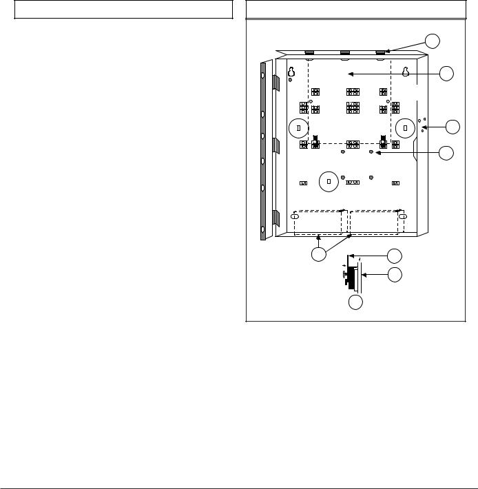
2.Mount the circuit board to the enclosure. See Figure 1.
Figure 1: Enclosure
|
1 |
|
2 |
|
3 |
|
4 |
5 |
6 |
|
7 |
|
8 |
1 - View to show retainer tabs. Insert board between tabs to secure.
2 - Circuit location
3 - Tamper switch mounting location
4 - Support post
5 - Battery location
6 - Enclosure
7 - Circuit board
8 - Support post assembly
Bosch Security Systems | 6/03 | 33829E
EA500 | Installation Instructions | 4.0 Wiring |
EN | 3 |
|
|
4.0Wiring
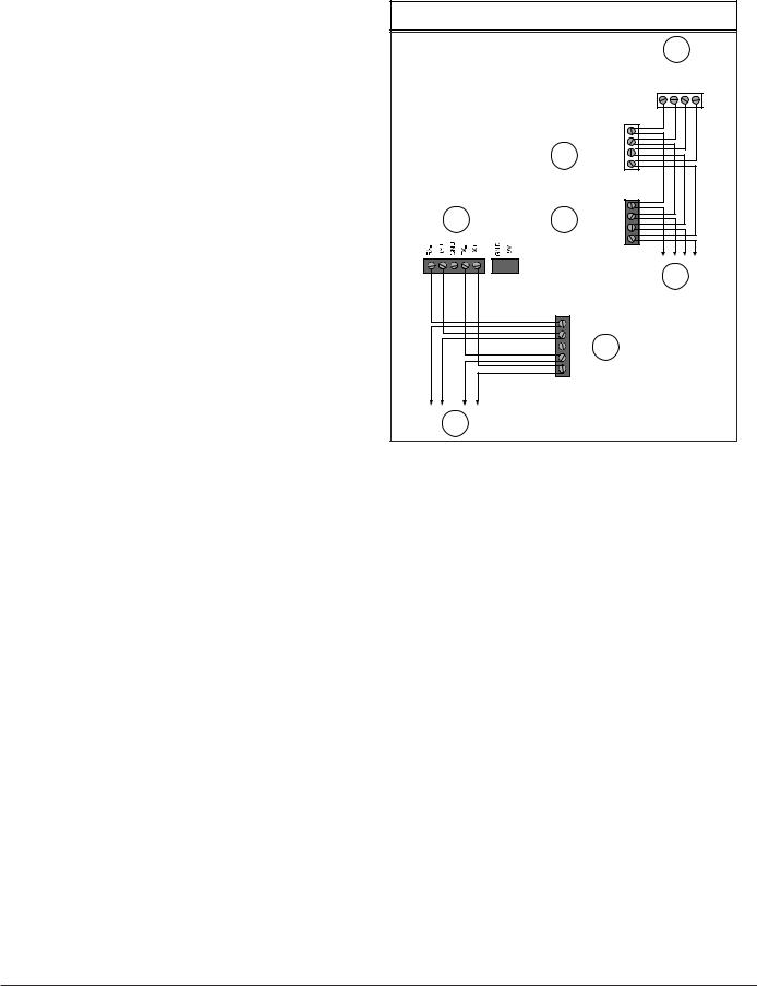
Wire the transponder according to Figure 2.
The wiring to the receivers and alert units can be as home-run (individual), daisy-chain (device to device), or a combination of both. T-tapping is also acceptable. The recommended cable is 4-conductor, 18 AWG
(1.2 mm [0.05 in.]) fire rated.
Wiring from SE485 to the transponders can be home-run (individual), daisy-chain (device to device), or a combination of both. T-Tapping is also acceptable. The recommended cable is 4-conductor, twisted pair, non-shielded, 22 AWG (0.8 mm [0.03 in.]).
Figure 2: Wiring
1
_ + _ + BUS 0 PWR 0
|
|
_ |
|
|
|
|
|
|
|
|
|
|
|
|
|
|
|
|
|
BUS |
|
|
|
|
|
+ |
|
|
|
|
2 |
_ |
|
|
|
|
POWER |
|
|
|
|
|
|
+ |
|
|
|
|
|
_ |
|
|
|
5 |
3 |
BUS |
|
||
+ |
|
|
|
||
_ |
|
|
|
||
POWER
+
|
4 |
|
- |
|
|
TX |
|
|
+ |
4 |
|
GND |
||
|
||
- |
|
|
RX |
|
|
+ |
|
6
1 - Transponder
2 - Typical receiver
3 - Typical output module
4 - To next device
5 - SE485
6 - To next transponder
Bosch Security Systems | 6/03 | 33829E
 Loading...