


EC Large Series
072, 096, 120, 150, 151, 180, 181, 210, 240, 242, 300, 360.
Installation, operation and Maintenance Manual
T111970289 (01/15)

2 | |
EC Series |
|
|
CONTENTS |
|
Model Nomenclature.......................................................... |
3 |
Initial Inspection................................................................ |
4 |
General Description........................................................... |
4 |
Moving and Storage........................................................... |
5 |
Location............................................................................ |
5 |
INSTALLATION .................................................................. |
5 |
MOUNTING VERTICALLY............................................... |
5 |
MOUNTING HORIZONTALY............................................ |
5 |
CONDENSATE DRAIN ......................................................... |
6 |
Duct System...................................................................... |
6 |
Piping ............................................................................... |
7 |
Electrical .......................................................................... |
7 |
ECM INTERFACE BOARD............................................... |
8 |
Thermostat Connections .................................................... |
9 |
Safety Devices and the UPM Controller ............................. |
10 |
Electronic Thermostat Installation..................................... |
13 |
Water Quality................................................................... |
15 |
UPM Sequence of Operation............................................. |
14 |
Water Quality table........................................................... |
15 |
Heat Recovery Package ................................................... |
16 |
Typical Connection Piping (HRP).................................. |
16 |
Water Tank PrECaration:............................................. |
16 |
HR Water Piping ........................................................ |
16 |
Water Tank Refill............................................................. |
17 |
Initial Start-Up........................................................... |
17 |
Hot Gas Reheat (HGRH).............................................. |
17 |
Sequence of Operation .................................................... |
18 |
Cooling Mode ............................................................ |
18 |
Heating Mode............................................................ |
18 |
Application considerations............................................... |
18 |
Well Water Systems ................................................... |
18 |
Installation of Pressure Regulating Valves......................... |
19 |
Cooling Tower/Boiler Systems.......................................... |
19 |
Geothermal (Earth-Coupled) Systems .......................... |
21 |
System Checkout............................................................. |
22 |
Unit Start-up ................................................................... |
22 |
Maintenance ................................................................... |
23 |
Unit Check-Out Sheet ...................................................... |
24 |
Customer Data .......................................................... |
24 |
Unit Nameplate Data.................................................. |
24 |
Operating Conditions................................................. |
24 |
Auxiliary Heat ........................................................... |
24 |
troubleshooting .............................................................. |
25 |
Belt drive Motor |
|
Table............................................................................... |
28 |
Blower Performance |
|
Table.............................................................................. |
29 |
Water side Pressure Drop |
|
Table............................................................................... |
30 |
Operating temperatures and Pressures............................. |
31 |
Wiring diagrams.............................................................. |
34 |
Notes ............................................................................. |
46 |
Key to symbols and safety instructions
Key to symbols
Warnings
Warnings in this document are identified by a warning triangle printed against a grey background.
Keywords at the start of a warning indicate the type and seriousness of the ensuing risk if measures to prevent the risk s are not taken.
The following keywords are defined and can be used in this document:
•NOTE indicates a situation that could result in damage to property or equipment.
•CAUTION indicates a situation that could result in minor to medium injury.
•WARNING indicates a situation that could result in severe injury or death.
•DANGER indicates a situation that will result in severe injury or death.
T111970289 (2015/01) |
Subject to change without prior notice |
EC Series |
Series EC
1 # Figure
(2015/01) T111970289
|
EC |
300 - |
4 VT C - S B S I U A - X X T |
X X X X X X |
1 X X X X 6 X X X X S |
B A |
|
|
|
EC |
|
|
|
|
|
|
CODE STRING LEVEL |
|
|
SIZE |
|
|
|
|
|
|
B - Bosch |
|
|
072 |
|
|
|
|
|
|
STANDARD/SPECIAL |
|
|
096 |
|
|
|
|
|
|
S - Standard |
|
|
120 |
|
|
|
|
|
|
A - Special #1 |
|
|
150 |
|
|
|
|
|
|
B - Special #2 |
|
|
180 |
|
|
|
|
|
|
OPEN |
|
|
210 |
|
|
|
|
|
|
MOTOR BLOWER ORIENTATION |
|
|
240 |
|
|
|
|
|
|
X - Blower and Motor Standard Orientation |
|
|
300 |
|
|
|
|
|
|
B - Blower Rotated 180 Deg, Motor Standard |
|
|
360 |
|
|
|
|
|
|
M - Blower Standard, Motor Rotated 1 |
|
|
VOLTAGE |
|
|
|
|
|
|
N - Both Blower and Motor Rotated 180 Deg |
|
|
1 |
208-230/60/1 |
|
|
|
|
X - N/A |
|
|
|
3 |
208-230/60/3 |
|
|
|
|
MOTOR HP (BELT DRIVE ONLY) |
|
|
|
4 |
460/60/3 |
|
|
|
|
|
A - 1 |
|
|
5 |
575/60/3 |
|
|
|
|
|
B - 1.5 |
|
|
CABINET CONFIGURATION |
|
|
|
|
|
C - 2 |
|
|
|
VT - Vertical |
|
|
|
|
|
|
D - 3 |
|
|
HZ - Horizontal |
|
|
|
|
|
E - 5 |
|
|
|
COAX OPTIONS |
|
|
|
|
|
|
AIR FILTRATION |
|
|
C - Copper |
|
|
|
|
|
|
1 - Standard Throw Away |
|
|
N - Cupro-Nickel |
|
|
|
|
|
3 - 2" 4 Sided Filter Rack with 1" Filter |
|
||
X - No condenser |
|
|
|
|
|
8 - 2" 2 Sided Filter Rack |
|
|
|
WATER CONNECTIONS |
|
|
|
|
|
OPEN |
|
|
|
F - Front |
|
|
|
|
|
|
ECONOMIZER |
|
|
S - Side |
|
|
|
|
|
|
X - None |
|
|
X - N/A |
|
|
|
|
|
|
E - Economizer With 3 Way Valve and Controls |
|
|
RETURN AIR CONFIGURATION |
|
|
|
|
H - Hot Water Coil |
|
|
||
B - Back |
|
|
|
|
|
|
X - None |
|
|
F - Front |
|
|
|
|
|
CONTROLS |
|
|
|
L - Left |
|
|
|
|
|
|
X - Standard |
|
|
R - Right |
|
|
|
|
|
M - DDC - Multi-Protocol (BacNET, Modbus, N2) |
|
||
DISCHARGE AIR CONFIGURATION |
|
|
|
|
P - DDC - Multi-Protocol (BacNET, Modbus, N2) w/ Expander |
|
|||
T - Top |
|
|
|
|
|
|
L - DDC - LonWorks |
|
|
F - Front |
|
|
|
|
|
|
G - DDC - LonWorks w/ Expander |
|
|
R - Rear |
|
|
|
|
|
|
I - Inverter |
|
|
E - End Blow |
|
|
|
|
|
J - DDC - Multi-Protocol (BacNET, Modbus, N2) with Inverter |
|
||
S - Straight Through |
|
|
|
|
|
T - DDC - Multi-Protocol (BacNET, Modbus, N2) with Inverter w/ Expander |
|
||
FAN/MOTOR OPTIONS |
|
|
|
|
|
K - DDC - LonWorks with Inverter |
|
|
|
I - Belt Drive, Inverter Duty |
|
|
|
|
C - DDC - LonWorks with Inverter |
|
|
||
B - Belt Drive |
|
|
|
|
|
O - Carrier Open Protocol Controller |
|
||
AIR COIL |
|
|
|
|
|
|
V - Carrier Open Protocol Controller w/ Inverter |
|
|
U - Uncoated |
|
|
|
|
|
TRANSFORMER |
|
|
|
D - DuoGuard |
|
|
|
|
|
7 - 75 VA |
|
|
|
REVISION LEVEL |
|
|
|
|
|
1 - 100 VA |
|
|
|
A - Current |
|
|
|
|
|
|
REFRIGERATION CIRCUIT OPTIONS |
|
|
ELECTRIC HEAT |
|
|
|
|
|
|
X - None |
|
|
X - None |
|
|
|
|
|
H - Hot Gas Reheat - On/Off |
|
|
|
CABINET CONSTRUCTION |
|
|
|
|
|
B - Hot Gas Bypass |
|
|
|
A - G90 Steel / 1/2" Standard 1.5LB Dual Density Fiberglass |
|
|
|
C - Hot Gas Bypass with Hot Gas Reheat |
|
||||
C - G90 Steel / 1/2" Closed Cell Foam |
|
|
|
M - Modulating Hot Gas Reheat |
|
||||
D - G90 Steel / 1/2" Standard 1.5LB Dual Density Fiberglass, Extra Quiet |
|
|
|
S - Straight Cool |
|
|
|||
F - G90 Steel / 1/2" Closed Cell Foam, Extra Quiet |
|
|
|
GENERAL ELECTRICAL OPTIONS(UP TO 5 AVAILABLE PER UNIT |
|
||||
APPLICATION |
|
|
|
|
|
A - EMS relay |
D - Phase Monitor |
G - Boilerless control |
X - As default for non used electrical codes |
T - TXV Option |
|
|
|
|
B - Blower Monitor Relay |
E - Pump/valve relay |
H - Flow proving switch |
Z - EMS + Pump/valve relay |
|
G - EXTENDED RANGE W/ SCHRADER VALVE (Geothermal) |
|
|
C - Compressor Monitor Relay |
M - Wire to 208 V |
K - Fire Alarm Relay/Dual Power |
|
|||
|
|
|
|
|
|
|
|
|
|
NOMENCLATURE MODEL
Series EC
3 | Nomenclature Model
4 | Initial Inspection |
EC Series |
|
|
WARNING: Installation and servicing of this equipment can be hazardous due to system pressure and electrical components. Only trained and qualified personnel should install, rECair, or service the equipment.
WARNING: Before performing service or maintenance operations on the system, turn off main power to the unit. Electrical shock could cause personal injury or death.
CAUTION: When working on equipment, always observe precautions described in the literature, tags, and labels attached to the unit. Follow all safety codes. Wear safety glasses and work gloves. Use a quenching cloth for brazing, and place a fire extinguisher close to the work area.
NOTE: All refrigerant discharged from this unit must be recovered WITHOUT EXCECTION. Technicians must follow industry accECted guidelines and all local, state, and federal statutes for the recovery and disposal of refrigerants. If a compressor is removed from this unit, refrigerant circuit oil will remain in the compressor. To avoid leakage of compressor oil, refrigerant lines of the compressor must be sealed after it is removed.
NOTE: To avoid equipment damage, DO NOT use these units as a source of heating or cooling during the construction process. Doing so may affect the unit’s warranty. The mechanical components and filters will quickly become clogged with construction dirt and debris, which may cause system damage.
NOTE: To avoid the release of refrigerant into the atmosphere, the refrigerant circuit of this unit must be serviced only by technicians who meet local, state, and federal proficiency requirements.
INITIAL INSPECTION
1
2
3
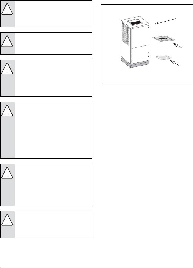
Figure # 2
[1]EC Series Water-to-Air Heat Pump
[2]Installation and Operation Manual
[3]Hanging Bracket kit (HZ unit only)
Be certain to inspect all cartons or crates on each unit as received at the job site before signing the freight bill. Verify that all items have been received and that there are no visible damages; note any shortages or damages on all copies of the freight bill. In the event of damage or shortage, remember that the purchaser is responsible for filing the necessary claims with the carrier. Concealed damages not discovered until after removing the units from the packaging must be rECorted to the carrier within 24 hours of receipt.
GENERAL DESCRIPTION
EC Series Water-to-Air Heat Pumps provide the best combination of performance and efficiency available. Safety devices are built into each unit to provide the maximum system protection possible when properly installed and maintained.
All EC water to Air Heat Pumps conform to UL1995 standard and are certified to CAN/CSA C22.2 No 236 by Intertek-ETL.The Water-to-Air Heat Pumps are designed to operate with entering fluid temperature between 20°F to 90°F in the heating mode and between 30°F to 120°F in the cooling mode.
T111970289 (2015/01) |
Subject to change without prior notice |
EC Series |
EC Series |
Moving and Storage | 5 |
|
|
NOTE: 50° Minimum Entering Water Temperature (EWT) for well water applications with sufficient water flow to prevent freezing. Antifreeze solution is required for all closed loop applications. Cooling Tower/Boiler and Geothermal applications should have sufficient antifreeze solution to protect against extreme conditions and equipment failure. Frozen water coils are not covered under warranty.
NOTE: This product should not be used for temporarily heating/cooling during construction. Doing so may Affect the units warranty.
MOVING AND STORAGE
If the equipment is not needed for immediate installation upon its arrival at the job site, it should be left in its shipping carton and stored in a clean, dry area. Units must only be stored or moved in the normal upright position as indicated by the “UP” arrows on each carton at all times.
For storage If unit stacking is required, stack units as follows:
Do not stack units larger than 6 tons.
Vertical units less than 6 tons, no more than two high.
Horizontals units less than 6 tons, no more than three high.
LOCATION
Locate the unit in an indoor area that allows easy removal of the filter and access panels, and has enough room for service personnel to perform maintenance or repair. Provide sufficient room to make fluid, electrical, and duct connection(s). If the unit is located in a confined space such as a closet, provisions must be made for return air to freely enter the face of unit’s air coil. On horizontal units, allow adequate room below the unit for a condensate drain trap and do not locate the unit above supply piping.
NOTE: These units are not approved for outdoor installation; therefore, they must be installed inside the structure being conditioned. Do not locate in areas that are subject to freezing.
INSTALLATION
MOUNTING VERTICALLY
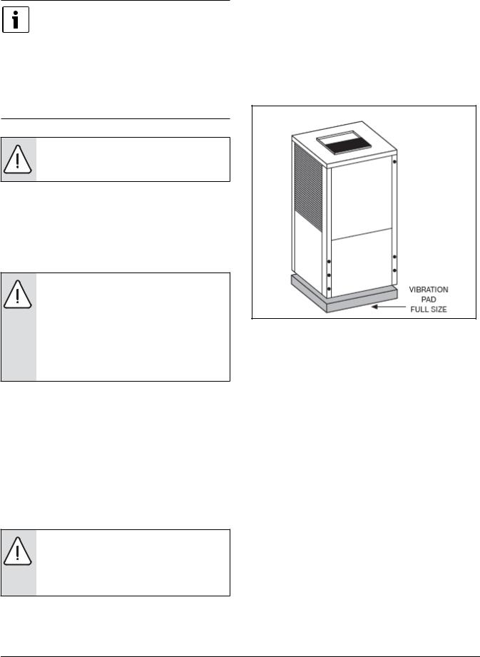
Vertical units up to six tons are available in left or right air return configurations. Vertical units should be mounted level on a vibration absorbing pad slightly larger than the base to minimize vibration transmission to the building structure. It is not necessary to anchor the unit to the floor. (See Figure #3).
Figure # 3
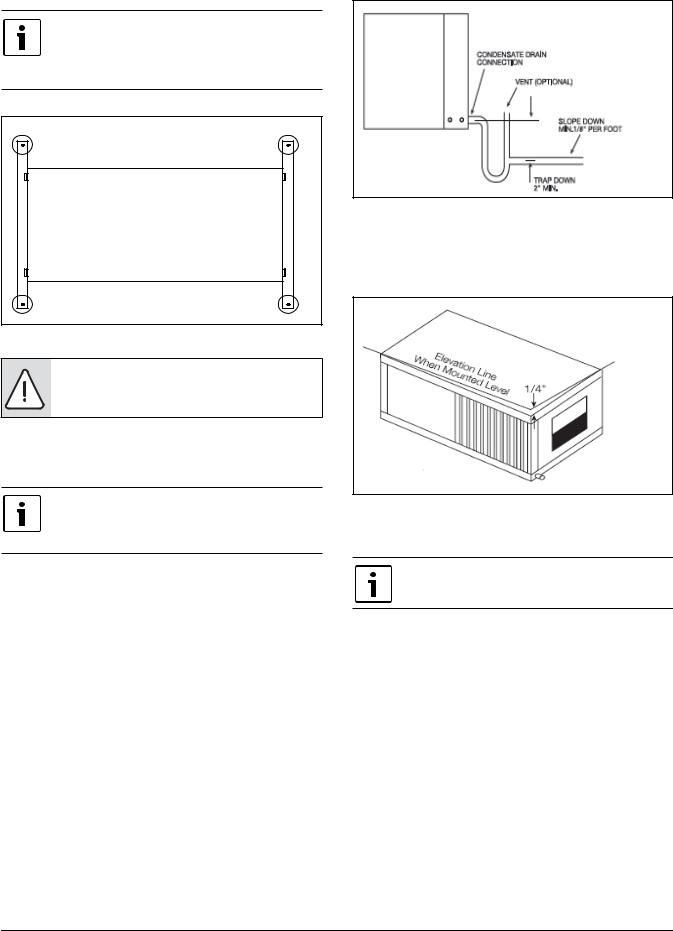
MOUNTING HORIZONTALY
While horizontal units may be installed on any level surface strong enough to hold their weight, they are typically suspended above a ceiling by threaded rods. The rods are usually attached to the unit corners by the base frame support rails , with mounting holes present (See Figure #4). The rods must be securely anchored to the ceiling. Horizontal units installed above the ceiling must conform to all local codes. An auxiliary drain pan if required by code, should be at least four inches larger than the bottom of the heat pump. Plumbing connected to the heat pump must not come in direct contact with joists, trusses, walls, etc.some applications require an attic floor installation of the horizontal unit. In this case the unit should be set in a full size secondary drain pan on top of a vibration absorbing mesh. The secondary drain pan prevents possible condensate overflow or water leakage damage to the ceiling. The secondary drain pan is usually placed on a plywood base isolated from the ceiling joists by additional layers of vibration absorbing mesh. In both cases, a 3/4” drain connected to this secondary pan should be run to an eaves at a location that will be noticeable.
EC Series |
T111970289 (2015/01) |
6 | CONDENSATE DRAIN |
EC Series |
|
|
NOTE: IF unit is located in a crawl space, the bottom of the unit MUST be at least 4” above grade to prevent flooding of the electrical parts due to heavy rains.
Figure # 4 |
NOTE: Plumbing connected to the heat pump must not come in direct contact with joists, trusses, walls, etc.
CONDENSATE DRAIN
If equipped with float style condensate
overflow switch, final adjustment must be
made in the field.
A drain line must be connected to the heat pump and pitched away from the unit a minimum of 1/8” per foot to allow the condensate to flow away from the unit.
This connection must be in conformance with local plumbing codes. A trap must be installed in the condensate line to insure free condensate flow. (Heat Pumps are not internally trapped).
A vertical air vent is sometimes required to avoid air pockets.(See Figure #5).
The length of the trap depends on the amount of positive or negative pressure on the drain pan. A second trap must not be included.
Figure # 5
The horizontal unit should be pitched approximately 1/4” towards the drain in both directions, to facilitate condensate removal. (See Figure #6)
Figure # 6
DUCT SYSTEM
Supply air duct and return air duct flanges are shipped unfolded with unit.
A supply air outlet collar and return air duct flange are provided on all units to facilitate duct connections. Fold the duct flange outwards along the perforated line. Refer to unit Dimensional Drawings for physical dimensions of the collar and flange. (Pg#33 through Pg#34)
A flexible connector is recommended for supply and return air duct connections on metal duct systems. All metal ducting should be insulated with a minimum of one inch duct insulation to avoid heat loss or gain and prevent condensate forming during the cooling operation.
T111970289 (2015/01) |
Subject to change without prior notice |
EC Series |

EC Series |
Piping | 7 |
|
|
NOTE: Application of the unit to no insulated duct work is not recommended as the unit’s performance will be adversely affected.
NOTE: The factory provided air filter must be removed when using a filter back return air grill. The factory filter should be left in place on a free return system
NOTE: Do not connect discharge ducts directly to the blower outlet.
If the unit will be installed in a new installation which includes new duct work, the installation should be designed using current ASHRAE procedures for duct sizing.
If the unit is to be connected to existing duct work, a check should be made to assure that the duct system has the capacity to handle the air required for the unit application. If the duct system is too small, larger duct work should be installed. Check for existing leaks and repair.
The duct system and all diffusers should be sized to handle the designed air flow quietly. To maximize sound attenuation of the unit blower, the supply and return air plenums should be insulated. There should be no direct straight air path thru the return air grille into the heat pump.
The return air inlet to the heat pump must have at least one 90 degree turn away from the space return air grille.
If air noise or excessive air flow are a problem, the blower speed can be changed to a lower speed to reduce air flow.
(Refer to ECM motor interface board section in Figure#11)
PIPING
Supply and return piping must be as large as the unit connections on the heat pump (larger on long runs).
NOTE: Never use flexible hoses of a smaller inside diameter than that of the fluid connections on the unit.
EC units are supplied with either a copper or optional cupro-nickel condenser. Copper is adequate for ground water that is not high in mineral content.
NOTE: Proper testing is recommended to assure the well water quality is suitable for use with water source equipment.
In conditions anticipating moderate scale formation or in brackish water a cupro-nickel heat exchanger is recommended.
NOTE: Both the supply and discharge water lines will sweat if subjected to low water temperature. These lines should be insulated to prevent damage from condensation.
All manual flow valves used in the system must be ball valves. Globe and gate valves must not be used due to high pressure drop and poor throttling characteristics.
NOTE: Never exceed the recommended water flow rates as serious damage or erosion of the water-to-refrigerant heat exchanger could occur.
Always check carefully for water leaks and rECair appropriately. Units are equipped with female pipe thread fittings. Consult Unit Dimensional Drawings. (Pg#33 through Pg#34)
NOTE: Teflon tape sealer should be used when connecting water piping connections to the units to insure against leaks and possible heat exchanger fouling.
NOTE: Do not overtighten the connections.
Flexible hoses should be used between the unit and the rigid system to avoid possible vibration. Ball valves should be installed in the supply and return lines for unit isolation and unit water flow balancing.
ELECTRICAL
Refer to electrical component box layout. (Figure#10)
WARNING: Field wiring must comply with local and national electric codes.
EC Series |
T111970289 (2015/01) |
 Loading...