


EXTEGRA IP 9000 FX
Bosch EXTEGRA IP 9000 FX, NXF-9130, NXF-9230, NXF-9130-A4, NXF-9230-A4 Installation Manual
...
EXTEGRA IP 9000 FX
NXF-9x30
Installation Manual / Manuel d'installation
english
français


Table of contents
1
Safety 4
1.1 About this Manual 4
1.2 Legal Information 4
1.3 Safety Precautions 4
1.4 Important Safety Instructions 5
1.5 FCC & ICES compliance 6
1.6 UL Certification 7
1.7 Explosion Protected Certifications 7
1.8 Joint Information 8
1.9 Warranty / Limitation of Liability 9
1.10 Customer Support and Service 10
2
Product Description 11
2.1 Unpacking 11
2.2 Parts List 12
2.2.1 Parts Included with the Product 12
2.2.2 User-supplied Parts 12
3
Planning 13
3.1 Dimensional Drawings 13
3.2 Initial Preparations 14
4
Installation Overview 15
5
Install the Optional Media Storage Card 17
6
Connections 20
6.1 Power Cable Requirements 20
6.1.1 Wire Distance Guide 20
6.2 Ethernet Cable Requirements 20
6.3 Alarm Cable Requirements 21
6.4 Audio Cable Requirements 21
6.5 Making the Connections 21
7
Mounting 24
7.1 Mounting the Unit 24
7.2 Installing the Sunshield 26
8
Troubleshooting 27
8.1 Function Test 27
8.2 Resolving Problems 27
8.3 Customer Service 28
9
Maintenance 29
9.1 Repairs 29
9.2 Replacement of the Mounting Cradle 29
10
Decommissioning 30
EXTEGRA IP 9000 FX Table of Contents | en
3
Bosch Security Systems Installation Manual / Guide d'installation 2015.03 | 1.7 | F.01U.304.260
Safety
About this Manual
This manual has been compiled with great care and the information it contains has been
thoroughly verified. The text was complete and correct at the time of printing. Because of the
ongoing development of products, the content of the manual may change without notice.
Bosch Security Systems accepts no liability for damage resulting directly or indirectly from
faults, incompleteness, or discrepancies between the manual and the product described.
Legal Information
Copyright
This manual is the intellectual property of Bosch Security Systems, Inc. and is protected by
copyright. All rights reserved.
Trademarks
All hardware and software product names used in this document are likely to be registered
trademarks and must be treated accordingly.
Safety Precautions
In this manual, the following symbols and notations are used to draw attention to special
situations:
Danger!
High risk: This symbol indicates an imminently hazardous situation such as “Dangerous
Voltage” inside the product. If not avoided, this will result in an electrical shock, serious bodily
injury, or death.
!
Warning!
Medium risk: Indicates a potentially hazardous situation. If not avoided, this may result in
minor or moderate injury.
!
Caution!
Low risk: Indicates a potentially hazardous situation. If not avoided, this may result in
property damage or risk of damage to the unit.
Notice!
This symbol indicates information or a company policy that relates directly or indirectly to the
safety of personnel or protection of property.
1
1.1
1.2
1.3
4
en | Safety EXTEGRA IP 9000 FX
2015.03 | 1.7 | F.01U.304.260 Installation Manual / Guide d'installation Bosch Security Systems
Important Safety Instructions
Read, follow, and retain all of the following safety instructions. Heed all warnings on the unit
and in the operating instructions before operation.
!
Caution!
TO REDUCE THE RISK OF ELECTRIC SHOCK, DISCONNECT THE POWER SOURCE WHILE
INSTALLING THE CAMERA.
!
Caution!
Installation must be made by qualified personnel and conform to ANSI/NFPA 70 (the National
Electrical Code® (NEC)), Canadian Electrical Code, Part I (also called CE Code or CSA C22.1),
and all applicable local codes. Bosch Security Systems, Inc. accepts no liability for any
damages or losses caused by incorrect or improper installation.
!
Warning!
INSTALL EXTERNAL INTERCONNECTING CABLES IN ACCORDANCE TO NEC, ANSI/NFPA70
(FOR US APPLICATION) AND CANADIAN ELECTRICAL CODE, PART I, CSA C22.1 (FOR CAN
APPLICATION) AND IN ACCORDANCE TO LOCAL COUNTRY CODES FOR ALL OTHER
COUNTRIES. BRANCH CIRCUIT PROTECTION INCORPORATING A 20 A, 2-POLE LISTED
CIRCUIT BREAKER OR BRANCH RATED FUSES ARE REQUIRED AS PART OF THE BUILDING
INSTALLATION. A READILY ACCESSIBLE 2-POLE DISCONNECT DEVICE WITH A CONTACT
SEPARATION OF AT LEAST 3 mm MUST BE INCORPORATED.
Adjustment of controls - Adjust only those controls specified in the operating instructions.
Improper adjustment of other controls may cause damage to the unit.
Power cord and plug protection - Protect the power cord from being walked on or pinched,
particularly at plugs, and at the point of exit from the device.
For units intended to operate with 230 VAC, 50 Hz, the input and output power cord must
comply with the latest versions of IEC Publication 227 or IEC Publication 245.
Power disconnect - Units with or without ON/OFF switches have power supplied to the unit
whenever the power cord is inserted into the power source; however, the unit is operational
only when the ON/OFF switch is in the ON position. The power cord is the main power
disconnect device for switching off the voltage for all units.
HPoE: Use only approved HPoE devices. High Power-over-Ethernet can be connected at the
same time as a 24 VAC power supply.
If auxiliary power (24 VAC) and HPoE are applied simultaneously, the camera selects auxiliary
input and shuts off the HPoE.
Servicing - Do not attempt to service this device yourself. Refer all servicing to qualified
service personnel.
1.4
EXTEGRA IP 9000 FX Safety | en
5
Bosch Security Systems Installation Manual / Guide d'installation 2015.03 | 1.7 | F.01U.304.260

FCC & ICES compliance
FCC & ICES Information
(U.S.A. and Canadian Models Only)
This device complies with part 15 of the FCC Rules. Operation is subject to the following
conditions:
– this device may not cause harmful interference, and
– this device must accept any interference received, including interference that may cause
undesired operation.
NOTE: This equipment has been tested and found to comply with the limits for a Class A
digital device, pursuant to Part 15 of the FCC Rules and ICES-003 of Industry Canada. These
limits are designed to provide reasonable protection against harmful interference when the
equipment is operated in a commercial environment. This equipment generates, uses, and
radiates radio frequency energy and, if not installed and used in accordance with the
instruction manual, may cause harmful interference to radio communications. Operation of
this equipment in a residential area is likely to cause harmful interference, in which case the
user will be required to correct the interference at his expense.
Intentional or unintentional modifications, not expressly approved by the party responsible for
compliance, shall not be made. Any such modifications could void the user's authority to
operate the equipment. If necessary, the user should consult the dealer or an experienced
radio/television technician for corrective action.
The user may find the following booklet, prepared by the Federal Communications
Commission, helpful: How to Identify and Resolve Radio-TV Interference Problems. This
booklet is available from the U.S. Government Printing Office, Washington, DC 20402, Stock
No. 004-000-00345-4.
Informations FCC et ICES
(modèles utilisés aux États-Unis et au Canada uniquement)
Ce produit est conforme aux normes FCC partie 15. la mise en service est soumises aux deux
conditions suivantes :
– cet appareil ne peut pas provoquer d'interférence nuisible et
–
cet appareil doit pouvoir tolérer toutes les interférences auxquelles il est soumit, y
compris les interférences qui pourraient influer sur son bon fonctionnement.
AVERTISSEMENT: Suite à différents tests, cet appareil s’est révélé conforme aux exigences
imposées aux appareils numériques de Classe A en vertu de la section 15 du règlement de la
Commission fédérale des communications des États-Unis (FCC). Ces contraintes sont
destinées à fournir une protection raisonnable contre les interférences nuisibles quand
l'appareil est utilisé dans une installation commerciale. Cette appareil génère, utilise et émet
de l'energie de fréquence radio, et peut, en cas d'installation ou d'utilisation non conforme aux
instructions, générer des interférences nuisibles aux communications radio. L’utilisation de ce
produit dans une zone résidentielle peut provoquer des interférences nuisibles. Le cas
échéant, l’utilisateur devra remédier à ces interférences à ses propres frais.
Au besoin, l’utilisateur consultera son revendeur ou un technicien qualifié en radio/télévision,
qui procédera à une opération corrective. La brochure suivante, publiée par la Commission
fédérale des communications (FCC), peut s’avérer utile : How to Identify and Resolve Radio-TV
Interference Problems (Comment identifier et résoudre les problèmes d’interférences de radio
et de télévision). Cette brochure est disponible auprès du U.S. Government Printing Office,
Washington, DC 20402, États-Unis, sous la référence n° 004-000-00345-4.
1.5
6
en | Safety EXTEGRA IP 9000 FX
2015.03 | 1.7 | F.01U.304.260 Installation Manual / Guide d'installation Bosch Security Systems
UL Certification
UL Disclaimer
Underwriter Laboratories Inc. ("UL") has not tested the performance or reliability of the
security or signaling aspects of this product. UL has only tested fire, shock and/or casualty
hazards as outlined in Standard(s) for Safety for Information Technology Equipment, UL
60950-1 . UL Certification does not cover the performance or reliability of the security or
signaling aspects of this product.
UL MAKES NO REPRESENTATIONS, WARRANTIES, OR CERTIFICATIONS WHATSOEVER
REGARDING THE PERFORMANCE OR RELIABILITY OF ANY SECURITY OR SIGNALING-RELATED
FUNCTIONS OF THIS PRODUCT.
Explosion Protected Certifications
Camera for Use in Hazardous Locations
Bosch Security Systems B.V.
NXF-9x30 camera models
24 VAC, Class 2, maximum 68 W (85 VA) (with heaters)
HPoE maximum 48 W (50 VA) (with heaters)
File # E333679
Class I, Groups C and D; Class II, Groups E, F, and G; Class III
Class I, Zone 1, AEx d IIB T6
; Ex d IIB T6 X
AEx tb IIIC T85°C Db
Ex tb IIIC T85°C Db X
IP68, Type 4X, Type 6P
ATEX Certification
DEMKO 15 ATEX 1444X
0539 II 2 GD
IECEx Certification
IECEx UL 15.0001X
Ex d IIB T6 Gb; Ex tb IIIC T85°C Db
Relevant standards associated with the ATEX and IECEx certifications.
EN 60079-0:2012+A11:2013
EN 60079-1:2007
EN 60079-31:2009
IEC 60079-1:2011 Edition 6
IEC 60079-1:2007-04 Edition 6
IEC 60079-31:2008 Edition 1
1.6
1.7
EXTEGRA IP 9000 FX Safety | en
7
Bosch Security Systems Installation Manual / Guide d'installation 2015.03 | 1.7 | F.01U.304.260
Joint Information
To obtain more information about the flameproof joints, please contact Bosch Security
Systems.
Joint-Threaded (All Models) Designation Pitch Full Threads
Engaged
Depth of
Engagement
Back Cover to Junction Box M 103 1.5 mm 7 minimum 14.5 mm
Housing to Junction Box M 103 2 mm 7 minimum 18.5 mm
Supply Opening Blanking Element to
Junction Box (four openings
provided)
3/4-14 NPT N/A 5 N/A
Housing to Front Cover M 103 2 mm 8 minimum 19.5 mm
!
Warning!
To reduce the risk of ignition of hazardous atmospheres, conduit runs must have a sealing
fitting connected to the wall of the enclosure.
!
Warning!
DO NOT OPEN WHEN AN EXPLOSIVE ATMOSPHERE MAY BE PRESENT.
1.8
8
en | Safety EXTEGRA IP 9000 FX
2015.03 | 1.7 | F.01U.304.260 Installation Manual / Guide d'installation Bosch Security Systems

Warranty / Limitation of Liability
The unit has a 3 year warranty.
BOSCH Security Systems warrants that its products, at the time of shipment by BOSCH
Security Systems, are free from defect in material or workmanship under normal use and
service for the respective warranty periods specified in the applicable Price Schedule or as
otherwise published.
To assure conformance with operating limitations, Buyer should refer to the applicable data
sheet.
The warranty is void (i) if the Product is not operated in conformance with installation,
environmental, mechanical or electrical requirements, or within thermal stress limits, or (ii) to
the extent that any malfunction is the result of misuse, abuse, vandalism, neglect, improper
installation or application, alteration, accident, or negligence in use, storage, transportation,
or handling or if the original identification markings on the product have been removed,
defaced or altered, lightning, electricity, water, fire, environment or other hazard, or act of
God, or other impact outside of normal operating guidelines.
The foregoing warranty is subject to Buyer’s (i) promptly written claim and (ii) timely provision
to BOSCH Security Systems of an opportunity to inspect and test the Product claimed to be
defective. Such inspection may be on Buyer’s premises and/or BOSCH Security Systems may
request the return of the Product at Buyer’s expense. However, BOSCH Security Systems shall
not be responsible for packing, inspection, or labor costs in connection with the return of
Product. No Product shall be accepted for warranty service that is not accompanied by a
Return Authorization issued by BOSCH.
The liability of BOSCH Security Systems hereunder or otherwise is solely and exclusively
limited to replacement (new or refurbished Product), repair, or credit of the amortized
purchase price, as BOSCH Security may elect, for any Product which is returned by Buyer
during the applicable warranty period, or services for which timely notice of defect has been
given by Buyer, and which are found by BOSCH Security to be subject to adjustment under
this warranty.
BOSCH Security System’s warranty shall not be enlarged, diminished, or affected by, and no
obligation or liability shall arise or grow out of BOSCH Security’s rendering or technical
advice, facilities, or services in connection with Buyer’s order to the products furnished
hereunder.
For more information about the warranty on this product, see the Warranty Repair section on
Bosch’s Customer Care web page at www.boschsecurity.us/en-us/Service/CustomerCare.
1.9
EXTEGRA IP 9000 FX Safety | en
9
Bosch Security Systems Installation Manual / Guide d'installation 2015.03 | 1.7 | F.01U.304.260

Customer Support and Service
If this unit needs service, contact the nearest Bosch Security Systems Service Center for
authorization to return and shipping instructions.
Service Centers
USA
Telephone: 800-366-2283 or 585-340-4162
Fax: 800-366-1329
Email: cctv.repair@us.bosch.com
Customer Service
Telephone: 888-289-0096
Fax: 585-223-9180
Email: security.sales@us.bosch.com
Technical Support
Telephone: 800-326-1450
Fax: 585-223-3508 or 717-735-6560
Email: technical.support@us.bosch.com
Repair Center
Telephone: 585-421-4220
Fax: 585-223-9180 or 717-735-6561
Email: security.repair@us.bosch.com
Canada
Telephone: 514-738-2434
Fax: 514-738-8480
Europe, Middle East & Africa Region
Please contact your local distributor or Bosch sales office. Use this link:
http://www.boschsecurity.com/startpage/html/europe.htm
Asia Pacific Region
Please contact your local distributor or Bosch sales office. Use this link:
http://www.boschsecurity.com/startpage/html/asia_pacific.htm
More Information
For more information please contact the nearest Bosch Security Systems location or visit
www.boschsecurity.com
1.10
10
en | Safety EXTEGRA IP 9000 FX
2015.03 | 1.7 | F.01U.304.260 Installation Manual / Guide d'installation Bosch Security Systems

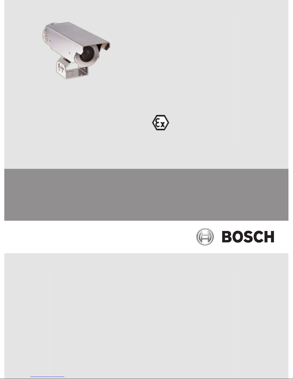
Product Description
The EXTEGRA IP 9000 is a high-performance, smart surveillance camera for explosive
environments. The camera offers unrivaled image quality in the worst lighting conditions. A
single pre-assembled unit with an integrated junction box, the camera is designed to be easy
to install. Through any of the four (4) 3/4 in. conduit entries, connections are made to the
convenient terminal connector; there is also space for any additional wiring.
The camera supports Power over Ethernet (HPoE, IEEE 802.3at, class 2) compliant network
cable connection and a 24 VAC power supply. You can connect both power sources
simultaneously for additional system reliability.
Both camera variants--
EXTEGRA IP starlight 9000 FX (NXF-9130) and EXTEGRA IP dynamic
9000 FX (NXF-9230)—have a professional-grade imaging platform with a 30x optical zoom (12x
digital) lens capable of delivering HD resolution in environments with ambient light extremes.
EXTEGRA IP starlight 9000 FX has 720p50/60 resolution. EXTEGRA IP dynamic 9000 FX has
both 720p50/60 and 1080p25/30 resolution.
Options for powering the camera
Both aluminum and stainless steel models of EXTEGRA IP 9000 can be powered by the
following devices:
– 24 VAC 50/60Hz (VG4-A-PSU1, VG4-A-PSU2)
– 60 W midspan (NPD-6001A)
– 95 W midspan (NPD-9501A)
– VIDEOJET connect 7000 (VJC-7000-90)
When using 24 VAC to power the camera, customers have the option to install an Optical Fiber
Converter (OFC) Kit (sold separately). When using HPoE to power the camera, this option is
not supported.
Unpacking
–
This equipment should be unpacked and handled with care. Check the exterior of the
packaging for visible damage. If an item appears to have been damaged in shipment,
notify the shipper immediately.
– Verify that all the parts listed in the Parts List below are included. If any items are
missing, notify your Bosch Security Systems Sales or Customer Service Representative.
– Do not use this product if any component appears to be damaged. Please contact Bosch
Security Systems in the event of damaged goods.
– The original packing carton is the safest container in which to transport the unit and must
be used if returning the unit for service. Save it for possible future use.
2
2.1
EXTEGRA IP 9000 FX Product Description | en
11
Bosch Security Systems Installation Manual / Guide d'installation 2015.03 | 1.7 | F.01U.304.260
Parts List
Parts Included with the Product
Quantity Item
1 EXTEGRA IP 9000 explosion-protected camera
1 Sunshield
4 M4 bolts, stainless steel, plus washers, for sunshield
1 1.5 mm hex key
1 Thread Adapter, ¾ in. NPT to M20, stainless steel
1 Multi-use tool
1 Installation Manual
User-supplied Parts
Quantity Item
3 M6 x 1.0 x 16 mm bolts with lock washers
1 Bottle of Jet-Lube® NCS-30 grease (as needed)
1 Tube of Molykote® BG 20 grease (as needed)
1 Tube of LA-CO Slic-Tite® Paste with PTFE (as needed)
2.2
2.2.1
2.2.2
12
en | Product Description EXTEGRA IP 9000 FX
2015.03 | 1.7 | F.01U.304.260 Installation Manual / Guide d'installation Bosch Security Systems
Planning
Refer to the information below before installing the unit. This section provides dimensional
information and guidelines to help plan your installation.
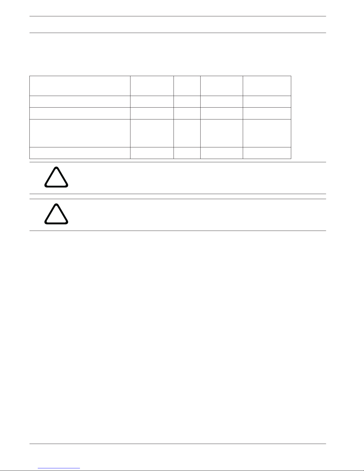
Dimensional Drawings
135
5.30
102
4.01
125
4.93
Figure 3.1: Front view
Ø
6.6
0.26
71°
60.0
2.36
3/4-in.
NPT x4
Figure 3.2: Bottom view
3
3.1
EXTEGRA IP 9000 FX Planning | en
13
Bosch Security Systems Installation Manual / Guide d'installation 2015.03 | 1.7 | F.01U.304.260
114
4.50
208
8.18
471
18.54
100
3.94
381
15.01
90°
Figure 3.3: Side view
Initial Preparations
The camera transmits zoom control commands and images over a TCP/IP network. It also
allows users to configure the camera display settings, camera operating settings, and to
configure the network parameters.
The camera incorporates a network video server in the IP module. The primary function of the
server is to encode video and control data for transmission over a TCP/IP network. With this
H.264 encoding, it is ideally suited for IP communication and for remote access to video
management systems. The use of existing networks means that integration with CCTV systems
or local networks can be achieved quickly and easily. Video images from a single camera can
be simultaneously received on several receivers.
– Determine the operating voltage at the installation site. The unit can receive an input
voltage range of 24 VAC ± 10%/HPoE without damage.
–
All units have been tested prior to shipment. It is advisable to check the unit’s operation
before installation.
!
Caution!
It is recommended that the installer wear an ESD strap or discharge any static electricity to
ground before handling any electronic components.
3.2
14
en | Planning EXTEGRA IP 9000 FX
2015.03 | 1.7 | F.01U.304.260 Installation Manual / Guide d'installation Bosch Security Systems
Installation Overview
This chapter details the installation guidelines for the EXTEGRA IP 9000. It is important that
you consider these steps.
!
Warning!
Do not apply power to the unit in an explosive environment unless the housing is fully
installed, the front and back caps are tightened, and all openings are appropriately plugged
and sealed. Disconnect power before servicing or disassembling the unit.
Based on the explosion-protected requirements of the installation location, determine the
appropriate installation method and follow all local guidelines and laws. It is important to
keep the following in mind during installation:
– The back end cap of the unit must be removed for access to the internal electronics. The
set screws on the caps are tightened at the factory. It is easier to remove the end cap
with the sunshield removed.
– When tightening the end caps, ensure that the threads are clean and lubricated with Jet-
Lube® NCS-30 grease or equivalent.
– Before tightening the end caps, ensure that the o-rings are clean and lubricated with
Molykote® BG 20 grease (from Dow Corning) or equivalent.
–
Ensure that all 3/4-in. NPT plugs are securely tightened in the 3/4-in. NPT conduit
openings and sealed with LA-CO Slic-Tite® Paste with PTFE, apply per manufacturer’s
instructions on the label.
– Ensure that the unit is wired and sealed appropriately either with a conduit seal or a
gland and cable rated for the intended environment. Use LA-CO Slic-Tite® Paste with
PTFE thread sealant on all conduit or gland threads.
– Carefully follow all manufacturers’ instructions for applying grease and paste products.
– All cable entry devices shall be ATEX/IECEx-certified for Ex d IIB T6 Gb and Ex tb IIIC
T85°C Db, rated at least 85 °C (185 °F), suitable for the conditions of use and installed
correctly.
– All unused conduit openings shall be closed with the supplied conduit plug, which is a
3/4 in. NPT plug certified for Class I, Groups C and D; Class II, Groups E, F, and G; and
Class III; Class I, Zone 1, AEx d IIB T6; Ex d IIB T6 X, AEx tb IIIC T85°C Db, and Ex tb IIIC
T85°C Db X hazardous locations.
– The maximum surface temperature will not exceed 85°C when operated in the ambient
temperature ranges for the different power options (24VAC vs. HPoE) and housing
material as specified in the following table:
Aluminum
housing
Stainless steel
housing
NXF-9130-A4
NXF-9230-A4
NXF-9130-S4
NXF-9230-S4
Ambient operating range
when powered by 24 VAC
-50 °C to 60 °C
(-58 °F to 140 °F)
-50 °C to 55 °C
(-58 °F to 131 °F)
Ambient operating range when powered by
HPoE
-40 °C to 60 °C
(-40 °F to 140 °F)
-40 °C to 55 °C
(-40 °F to 131 °F)
– If starting up the unit below -40 °C, there may be a delay (up to 30 minutes) between
when power is applied to the camera and when video output is available.
4
EXTEGRA IP 9000 FX Installation Overview | en
15
Bosch Security Systems Installation Manual / Guide d'installation 2015.03 | 1.7 | F.01U.304.260

– The joint between the junction box and housing is secured by a thread locker for
permanent securement. This joint shall not be removed because there may be damage to
the flame path threads.
– The device was subjected to the resistance to impact test at 2 J. It shall be installed
where it will not be subjected to impact.
– For ambient temperatures below –10 °C, use field wiring suitable for the minimum
ambient temperature.
Note: For instructions to configure the camera, refer to the Software Manual. Go to http://
www.boschsecurity.com
, navigate to the product page for your camera, and then locate the
document in the Documents tab.
16
en | Installation Overview EXTEGRA IP 9000 FX
2015.03 | 1.7 | F.01U.304.260 Installation Manual / Guide d'installation Bosch Security Systems
Install the Optional Media Storage Card
The camera can accept a customer-supplied SDHC or SDXC memory card (hereafter referred
to as “SD card”) for local storage. (The camera will not accept MicroSD cards.) Using an SD
card is optional.
!
Caution!
Risk of electrostatic discharge!
Use proper CMOS/MOS-FET handling precautions and observe proper ESD safety precautions
(such as wearing grounded wrist straps) to avoid electrostatic discharge.
Note: Disconnect power to the camera while adding or removing an SD card.
Ideally, you should install the card before connecting cables and mounting the camera. To
install the card,
follow these steps
:
!
Warning!
DO NOT OPEN WHEN AN EXPLOSIVE ATMOSPHERE MAY BE PRESENT.
Note: You may need to remove the sunshield to remove the front end cap more easily.
1. Loosen the set screw on the front end cap using the supplied hex key.
2. Loosen the front end cap using the supplied multi-use tool. To prevent damage to the oring, for every half turn counterclockwise turn back one quarter turn clockwise.
3. Unscrew the front end cap by hand.
Figure 5.1: Remove the front end cap
5
EXTEGRA IP 9000 FX Install the Optional Media Storage Card | en
17
Bosch Security Systems Installation Manual / Guide d'installation 2015.03 | 1.7 | F.01U.304.260
Notice!
Take care not to drop the end caps to prevent damage to the cap threads.
4. Remove the inner mounting bracket assembly from the front of the housing:
Note: Before removing the assembly from the housing, ensure that all connections to the User
Interface Board have been removed.
– Using the multi-use tool, loosen the two (2) bolts that hold the assembly.
Figure 5.2: Loosen the 2 bolts
– Pull the assembly out of the housing until the card slot is accessible.
Figure 5.3: Pull the assembly out of the housing
5. Orient the card so that the side with the golden contacts faces away from the camera and
towards the housing as you hold the card in front of the card slot.
6. Slide the card into the card slot. Press the card until you hear a click and the card locks into
place.
18
en | Install the Optional Media Storage Card EXTEGRA IP 9000 FX
2015.03 | 1.7 | F.01U.304.260 Installation Manual / Guide d'installation Bosch Security Systems
 Loading...