


DX4010V2
Installation Instructions
RS-232/USB Serial
EN Interface Module

DX4010V2 | Installation Instructions | Trademarks
Trademarks
•BlackBox® is either a registered trademark or a trademark of BlackBox Corporation in the United States and/or other countries.
2 |
Bosch Security Systems, Inc. | 9/08 | F01U083036-01 |

DX4010V2 | Installation Instructions | Contents
Contents |
|
|
1.0 |
General Information .................................... |
4 |
2.0 |
Specifications .............................................. |
4 |
3.0 |
Installation Standards ................................. |
4 |
4.0 |
Wiring........................................................... |
5 |
5.0 |
DX4010V2 Jumper Pin Settings ................ |
6 |
5.1 |
Enable LED Jumper Pins (P2) ..................... |
6 |
5.2 |
DB9 Ground Enable Pins (P1) ..................... |
6 |
5.3 |
Address DIP Switches.................................. |
7 |
6.0Remote Programming Direct Connection 7
7.0 |
DB9 DTE RS-232 Connector (P6) ............ |
10 |
8.0 |
RJ-16 Data Bus Connector (P3) .............. |
11 |
9.0 |
USB Data Bus Connector ........................ |
11 |
9.1 |
Installing USB Drivers ................................ |
11 |
Figures
Figure 1: DX4010V2 Component Layout .............. |
4 |
|
Figure 2: Control Panel Connections .................... |
5 |
|
Figure 3: External Power Supply Connections...... |
5 |
|
Figure 4: Serial Device Connections..................... |
5 |
|
Figure 5: Parallel Device Connections.................. |
6 |
|
Figure 6: P2 Jumper Settings ............................... |
6 |
|
Figure 7: DIP Switch Location and Orientation ..... |
7 |
|
Figure 8: DB9 Connector Layout ........................ |
10 |
|
Figure 9: |
P3 Connector....................................... |
11 |
Figure 10: |
Select File............................................ |
11 |
Figure 11: |
Security Warning ................................. |
11 |
Figure 12: |
Install Shield ........................................ |
11 |
Figure 13: |
Security Warning ................................. |
11 |
Figure 14: |
Destination Location ............................ |
12 |
Figure 15: Ready to Install .................................... |
12 |
|
Figure 16: |
Setup Status ........................................ |
12 |
Figure 17: |
Installation Complete ........................... |
12 |
Figure 18: USB Driver Installer ............................. |
12 |
|
Figure 19: |
Scanning.............................................. |
12 |
Figure 20: |
Installation Complete ........................... |
12 |
Figure 21: |
System Properties ............................... |
13 |
Figure 22: |
Device Manager................................... |
13 |
Figure 23: |
Panel Communication.......................... |
13 |
Tables
Table 1: |
DX4010V2 Specifications ...................... |
4 |
|
Table 2: |
Diagnostic LED Functions ..................... |
6 |
|
Table 3: |
Option Bus Address DIP Switch Settings8 |
|
|
Table 4: |
SDI Bus Address DIP Switch Settings ... |
9 |
|
Table 5: |
Alternate Wiring Configuration............. |
10 |
|
|
|
||
Bosch Security Systems, Inc. | 9/08 | F01U083036-01 |
3 |
||
DX4010V2 | Installation Instructions | 1.0 |
General Information |
|
|
1.0 General Information
The DX4010V2 is a data terminal equipment (DTE) configured RS-232/USB serial device interface. This module is designed to operate with compatible control panels. It connects to the control panel through the Option or SDI data bus.
The DX4010V2 is used to connect a PC with RPS, BIS, PC 9000, CMS 7000, or other third party software that uses a serial connection to the supported control panels. The module also supports a serial printer (or parallel printer with a converter box) for control panels that support a serial printer. The compatibility lists in Table 1 show support information.
2.0 Specifications
Table 1: DX4010V2 Specifications
|
|
|
|
|
Operating |
12 VDC nominal |
|
|
Voltage |
|
|
|
Current Draw |
55 mA nominal, 60 mA with |
|
|
|
|
diagnostic LEDs enabled |
|
Communication |
Programmable through the control |
|
|
Configuration |
panel. Refer to the appropriate |
|
|
|
|
control panel programming |
|
|
|
instructions. |
|
|
|
|
|
|
|
|
The baud rate for the printer output on a DS7400Xi must be greater than 300 baud.
Operating |
0°C to +50°C (+32°F to +122°F) |
Temperature |
|
Relative |
5 to 85% @ +30°C (+86°F) |
Humidity |
non-condensing |
Control Panel |
Option bus control panels: D6412, |
Compatibility |
D4412, DS7240, DS7220, DS7400Xi |
|
(v2.02 or higher) |
|
SDI bus control panels (v6.0 or |
|
higher): D9412GV2, D7412GV2, |
|
D7212GV2, D9412G, D7412G, |
|
D7212G, D9124, D9112, D7412, and |
|
D7212 |
Table 1: DX4010V2 Specifications (continued)
Application |
RPS: Supported on all compatible |
Compatibility |
control panels. |
PC 9000: Supported on SDI Bus control panels (D9412G, D7412G, D7212G, D9112, D7412, and D7212).
BIS: Supported on SDI Bus control panels, v6.3 and higher (D9412GV2, D7412GV2, D7212GV2, D9412G, D7412G, and D7212G).
CMS 7000: Supported on DS7400Xi Control Panels set at Mode 18 (v3.09 or higher).
Printers: Supported on compatible control panel.
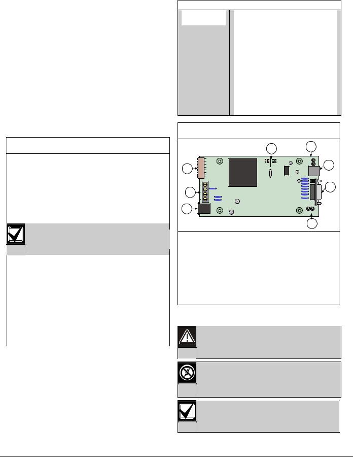
Figure 1: DX4010V2 Component Layout
|
|
5 |
6 |
|
|
|
LED |
|
Rx Tx |
Tx Rx |
7 |
4 |
BUS |
SER |
|
|
|
|
3 |
8 |
|
|
2 |
P1 |
|
|
|
DB9 GND |
P3 |
ENABLE |
1
1- DB9 GND enable pins (P1)
2- RJ-16 data bus connector (P3)
3- Data bus (TS1)
4- Address DIP switches (S1)
5- Diagnostic LEDs
6- Diagnostic LED enable pins (P2)
7- USB Connector (P7)
8- DB9 DTE RS-232 connector (P6)
3.0 Installation Procedure
Failure to follow the instructions in this manual can result in personal injury or damage to the equipment.
The DX4010V2 contains static-sensitive components and must be handled with care. Follow anti-static procedures when handling the modules.
Test according to NFPA 72 if used in fire applications.
4 |
Bosch Security Systems, Inc. | 9/08 | F01U083036-01 |

DX4010V2 | Installation Instructions | 4.0 |
Wiring |
|
|
1.Disconnect power to the control panel by unplugging the transformer and removing the red battery lead.
2.Remove screws from enclosure cover to access the DX4010V2 board.
3.Connect circuit wiring and install jumper pins. Refer to Section 4.0 Wiring on page 5.
4.Replace enclosure cover.
5.Connect a serial cable to the serial device. Refer to Section 7.0 DB9 DTE RS-232 Connector (P6) on page 10.
6.Reapply power to the control panel.
4.0 Wiring
Remove all power to the control panel (AC and standby battery) before making or breaking any connections. Failure to do so can result in personal injury or damage to the equipment.
Wire Length Restrictions
•0.8 mm (#22 AWG): 305 m (1000 ft)
•1.2 mm (#18 AWG): 610 m (2000 ft)
•USB or Serial Cables are not to exceed 2 meters (6 ft) in length.
SDI option bus wiring is limited to 305 m (1000 ft).
Connect the DX4010V2 to the control panel data and auxiliary power sources as shown in Figure 2.
Figure 2: Control Panel Connections
1 |
2 |
B |
3 |
G |
4 |
Y |
5 |
R |
6 |
1- DX4010V2 data bus
2- Control panel data bus
3- Option AUX common/SDI common (black)
4- Option data/SDI B (green)
5- Option data/SDI A (yellow)
6- Option AUX power +/SDI power (red)
If an external 12 VDC power supply is used, wire as shown in Figure 3.
Figure 3: External Power Supply Connections
1 |
2 |
|
3 |
|
4 |
|
5 |
|
6 |
+ |
- |
|
7 |
1- DX4010V2 data bus
2- Control panel data bus
3- Option AUX common/SDI common (black)
4- Option data/SDI B (green)
5- Option data/SDI A (yellow)
6- Option AUX power +/SDI power (red)
7- External 12 VDC power supply
Figure 4 shows serial device-to-DX4010V2 connections using the DB9 DTE RS-232 connector (P6).
Figure 4: Serial Device Connections
Rx Tx |
Tx Rx |
BUS |
SER |
P3
LED |
P2 |
P1 |
DB9 GND |
ENABLE |
1
1- Serial (RS-232) device such as a PC (with RPS, BIS, PC9000, or other third party application) or a serial printer for supported control panels.
Refer to Section 7.0 DB9 DTE RS-232 Connector (P6) on page 10 for additional information.
Bosch Security Systems, Inc. | 9/08 | F01U083036-01 |
5 |
 Loading...