


DS1
Table of contents
 Loading...
AT&T
DEFINITY
AT&T 555-025-101
April 1990
®
Communications
System
Issue 4
and System 75 and System 85
DS1/DMI/ISDN-PRI Reference

NOTICE
While reasonable efforts were made to ensure that the information
in this document was complete and accurate at the time of printing,
AT&T can assume no responsibility for any errors.
Changes or corrections to the information contained in this
document may be incorporated into future issues.
Prepared by
AT&T Technical Publications Department
Denver, Colorado
Copyright © 1990 AT&T
All Rights Reserved
Printed in USA

CONTENTS
ABOUT THIS DOCUMENT
PURPOSE
INTENDED AUDIENCES
PREREQUISITE SKILLS AND KNOWLEDGE
HOW THIS DOCUMENT IS ORGANIZED
HOW TO USE THIS DOCUMENT
TRADEMARKS AND SERVICE MARKS
RELATED SOURCES
HOW TO MAKE COMMENTS ABOUT THIS DOCUMENT
1. INTRODUCTION
FUNDAMENTALS OF DS1 SIGNALS
Channels
Framing Formats
Signaling Types
Line-Coding Formats
IMPORTANT CONCEPTS
Common-Channel Signaling
Alternate Voice/Data (AVD) Trunks
Bearer Capability (BC)
ISDN Call Processing
CBC Service Selection
Networking Restrictions and ISDN-PRI Limitations
xix
xix
xx
xx
xx
xxii
xxii
xxii
xxiii
1-1
1-1
1-7
1-10
1-14
1-16
1-22
1-22
1-22
1-23
1-25
1-28
1-29
2. NETWORK CONNECTIONS AND CONFIGURATIONS
NETWORK DIFFICULTIES
Hyperactivity
Glare
2-1
2-1
2-1
2-2
iii

iv CONTENTS
DS1/DMI PRIVATE-NETWORK CONNECTIONS
Generic 1, Generic 2, System 75, or System 85 to Another System
Host Computer to Another System
®
IDNX Multiplexer to Another System
IBM
Other Vendor Digital Switch to Another System
Analog Switch to Another System
OPS to Another System Via a D4-Channel Bank
DS1/DMI PUBLIC-NETWORK CONNECTIONS
4ESS to Another System (Special-Access Connection)
5ESS to Another System
DACS to Another System
Analog CO to Another System Via a D4-Channel Bank
DS1/DMI TERMINAL-EQUIPMENT CONNECTIONS
CDM
CEM to a BCM32000
ISDN-PRI PRIVATE-NETWORK CONNECTIONS
System 85 R2 to a System 85 R2V4, Generic 1, or Generic 2
System 85 or Generic 2 ISDN-PRI to Another Vendor’s Digital Switch
ISDN-PRI PUBLIC-NETWORK CONNECTIONS
2-3
2-3
2-3
2-4
2-4
2-5
2-5
2-6
2-6
2-7
2-8
2-8
2-9
2-9
2-10
2-12
2-12
2-13
2-13
System 85 R2V4, Generic 1, and Generic 2 to a 4ESS
Synchronization
System 85 R2V4, Generic 1, or Generic 2 to a DACS
System 85 or Generic 2 ISDN-PRI to a 5ESS
3. DS1 TRANSMISSION AND CABLING
METALLIC CABLING OPTIONS
DSX-1 Distance Limitations
Network Channel Terminating Equipment (NCTE)
On-Premises Cabling
Off-Premises Cabling
NONMETALLIC CABLING OPTIONS
CEM AND CDM CABLING CONFIGURATIONS
LINE EQUALIZER AND COMPENSATION SETTINGS
2-13
2-15
2-15
2-15
3-1
3-2
3-2
3-2
3-3
3-5
3-6
3-7
3-9

CONTENTS
v
System 85 Traditional Modules
Generic 1 and Generic 2 Universal Modules
4. THE DIGITAL LOSS PLAN
LOSS-PLAN IMPLEMENTATION AND PROVISIONING
Generic 2
Generic 1
PORT-TO-PORT LOSS VALUES
DS1/DMI/ISDN-PRI PORT LOSSES
TERMINATING A DS1 AT A CHANNEL BANK
Tie Trunk Ports
CO DID Trunk Ports
OPS Ports
5. SYNCHRONIZATION OF DIGITAL FACILITIES
THE NEED FOR SYNCHRONIZATION
SYNCHRONIZATION HIERARCHY
System 85 and Generic 2 Synchronization Architecture
System 85 and Generic 2 Synchronization Software Operation
CHANGES TO THE SCS SOFTWARE MADE AVAILABLE VIA SOFTWARE PATCHES
System 75 and Generic 1 Synchronization Architecture
System 75 and Generic 1 Synchronization Software Operation
The External Synchronization Clock
3-9
3-9
4-1
4-2
4-2
4-3
4-4
4-6
4-6
4-6
4-6
4-7
5-1
5-1
5-3
5-7
5-9
5-11
5-11
5-12
5-14
NETWORK SYNCHRONIZATION AND ENGINEERING
Selecting a Timing Source for the Switch
Internal Reference Selection Rules
External-Reference Selection Rules
AVAILABILITY OF SYNCHRONIZATION SOURCES
CONCLUSIONS ON SYNCHRONIZATION
USE OF GENERIC 2 AS A SYSTEM CLOCK REFERENCE
ISDN-PRI Trunk Facilities (ANN35 or TN767 with TN755)
Line-Only Mode DS1/DMI-BOS (ANN11_ or TN767)
5-18
5-18
5-19
5-27
5-28
5-29
5-29
5-29
5-29

vi
CONTENTS
Line+Trunk Mode DS1/DMI-BOS (ANN35 or TN767 with TN555)
DMI-MOS (ANN35 or TN767 with TN755)
USE OF GENERIC 1 AS A SYSTEM CLOCK REFERENCE
Trunk-Mode ISDN-PRI (TN767)
Trunk-Mode Interface (ISDN-PRI + Robbed Bit) (TN767)
Line-Only Mode DS1/DMI-BOS (TN767)
Trunk-Mode DS1/DMI-MOS (TN767)
6. PORT TYPES/INSTALLATION COMPATIBILITIES
GENERIC 1 DS1/DMI-BOS
Operating Mode
Supported Port Types
GENERIC 1 ISDN-PRI
SYSTEM 85 DS1, TRADITIONAL MODULES (ANN11)
Operating Modes
Line+Trunk Mode Port Grouping Rules
Supported Port Types
SYSTEM 85 DS1 OR DMI-MOS, TRADITIONAL MODULES (ANN35)
Operating Mode
Port Grouping Rules
Supported Port Types
5-30
5-30
5-30
5-30
5-30
5-31
5-31
6-1
6-4
6-4
6-4
6-5
6-5
6-5
6-10
6-10
6-13
6-13
6-14
6-14
7. ADMINISTRATION OPTIONS AND REQUIREMENTS
SYSTEM 85 (R2V1 THROUGH R2V4)
Procedure 275 Word 4:
Procedure 276 Word 1:
Procedure 250 Word 1:
Procedure 260 Word 1:
Procedure 262 Word 1:
Procedure 354 Word 3:
Procedure 000 Word 4:
Procedure 210 Word 2:
ISDN Service — Enable/Disable
Other Feature Groups
DS1 — Carrier Designation
DS1/DMI/ISDN-PRI Physical Interface
ISDN Board Parameters
NPA-NXX Digits Assignment
NPA-NXX Index Designator
LDN, NPA, and NNX Attendant Partition Assignments
7-1
7-3
7-3
7-4
7-4
7-6
7-16
7-18
7-19
7-20

CONTENTS
vii
Procedure 010 Word 4:
Procedure 100 Word 1:
Procedure 100 Word 2:
Procedure 100 Word 3:
Procedure 101 Word 1:
Procedure 103 Word 1:
Procedure 116 Word 1:
Procedure 012 Word 1:
Procedure 012 Word 2:
Procedure 012 Word 3:
Procedure 309 Word 1:
Procedure 309 Word 5:
Procedure 321 Word 1:
Procedure 321 Word 5:
Procedure 107 Word 1:
Procedure 108 Word 1:
GENERIC 2
Line Side (B-Channel) BC and ISDN Routing Options
Trunk Group Type, Signaling, and Dial Access (ID) Code
Trunk Group Data Translations
ISDN Trunk Group Signaling Options
ISDN Trunk Group, SMDR, Digital Loss Plan, and AVD Assignments
Trunk Group Digit Collection and Trunk-Side BC
DS1/DMI/ISDN-PRI Trunk Assignments
Name Database
Name Database
Name Database
ARS Assignments and IXC/ISDN Network Identifier
ARS and ISDN Trunk — Network Characteristics
AAR Assignments and IXC/ISDN Network Identifier
AAR and ISDN Trunk — Network Characteristics
ISDN Trunk Verification by Terminal, Attendant, and ATMS
ISDN Trunk Group Terminating Test Line Number (Digits)
7-22
7-23
7-26
7-27
7-30
7-33
7-35
7-38
7-40
7-41
7-42
7-44
7-46
7-47
7-48
7-49
7-51
Procedure 275 Word 4:
Procedure 276 Word 1:
Procedure 250 Word 1:
Procedure 260 Word 1:
Procedure 262 Word 1:
Procedure 262 Word 2:
Procedure 262 Word 3:
Procedure 280 Word 1:
Procedure 354 Word 3:
Procedure 000 Word 4:
Procedure 210 Word 2:
Procedure 014 Word 1:
Procedure 014 Word 2:
Procedure 010 Word 4:
Procedure 100 Word 1:
Procedure 100 Word 2:
Procedure 100 Word 3:
ISDN Service — Enable/Disable
Other Feature Groups
SC/DS1 — Carrier Designation
DS1/DM1/ISDN-PRI Physical Interface
Additional DMI-MOS/ISDN-PRI Facility Options
ISDN-PRI D-Channel Backup
ISDN-PRI Codeset Map Assignments
ISDN-PRI Receive/Transmit Codeset Mapping
NPA-NXX Digits Assignment
NPA-NXX Index Designator
LDN, NPA, and NNX Attendant Partition Assignments
BCCOS Routing Options
BCCOS Data Options
Line Side (B-Channel) BC and ISDN Routing Options
Trunk Group Type Signaling and Dial Access (ID) Code
Trunk Group Data Translations
ISDN Trunk Group Signaling Options
7-51
7-52
7-53
7-54
7-65
7-67
7-69
7-71
7-72
7-74
7-75
7-76
7-78
7-80
7-81
7-84
7-86

viii
CONTENTS
Procedure 101 Word 1:
Procedure 103 Word 1:
Procedure 116 Word 1:
Procedure 012 Word 1:
Procedure 012 Word 2:
Procedure 012 Word 3:
Procedure 279 Word 1:
Procedure 309 Word 1:
Procedure 309 Word 5:
Procedure 321 Word 1:
Procedure 321 Word 5:
Procedure 107 Word 1:
Procedure 108 Word 1:
SYSTEM 75 (R1V2 AND R1V3)
Network Synchronization Options
Trunk Group/Trunk Group Members
GENERIC 1
Network Synchronization Options — DS1 and ISDN-PRI Applications
Trunk Group/Trunk Group Members — DS1 Trunk Applications
Processor Interface Data Module — ISDN-PRI Applications
Processor Channel Assignments — ISDN-PRI Applications
Interface Links — ISDN-PRI Applications
Trunking Considerations — ISDN-PRI Applications
Network Facilities — ISDN-PRI Applications
Trunk Group — ISDN-PRI Trunk Applications
Trunk Group Usage Allocation — ISDN-PRI Applications
Usage Allocation Plan Assignment Schedule — ISDN-PRI Applications
Trunk Group Member Assignments — ISDN-PRI Trunk Applications
SID Prefix Table — ISDN-PRI Applications
Routing Patterns — ISDN-PRI Applications
Hunt Group — ISDN-PRI Applications
ISDN Trunk Group, CDR, and Digital Loss Plan
Network Trunk Group Translations
DS1/DMI/ISDN-PRI Trunk Assignments
Name Database
Name Database
Name Database
Network Facilities Coding
ARS Route Tables
ARS–ISDN BCCOS
AAR Tables (Generic 2)
AAR–ISDN and Other Feature Parameters
ISDN Trunk Verification by Terminal, Attendant, and ATMS
ISDN Trunk Group TTL Number (Digits)
7-88
7-90
7-92
7-94
7-95
7-96
7-97
7-100
7-101
7-102
7-104
7-105
7-106
7-107
7-110
7-112
7-115
7-119
7-121
7-124
7-125
7-126
7-128
7-129
7-130
7-139
7-141
7-143
7-144
7-146
7-149
Terminating Extension Group — ISDN-PRI Applications
7-150

CONTENTS
ix
8. MAINTENANCE AND ALARMS
GENERIC 1 AND GENERIC 2 ISDN-PRI MAINTENANCE PHILOSOPHY
GENERIC 2 MAINTENANCE CAPABILITIES AND CONCERNS
Generic 2 Maintenance Procedures
Summary of Generic 2 Maintenance Capabilities
GENERIC 1 MAINTENANCE CAPABILITIES AND CONCERNS
Generic 1 Maintenance Procedures
Summary of Generic 1 Maintenance Capabilities
ALARMS
Circuit Pack Alarms
Facility Alarms
A. ADMINISTRATION REQUIREMENTS
B. SAMPLE INSTALLATION AND MAINTENANCE PROBLEMS
8-1
8-1
8-1
8-2
8-5
8-6
8-6
8-7
8-7
8-7
8-8
A-1
B-1
TRANSLATIONS-BASED PROBLEMS
TRUNKS AND TRUNK GROUPS
CDMs
CEMs
D4-Channel Banks
SYNCHRONIZATION-RELATED PROBLEMS
Loss of or No Synchronization
Leavenworth Loop
D4 Synchronization Problems
Digital CO Synchronization Problems
DACS
TYPICAL PHYSICAL INTERFACE CONNECTION PROBLEMS
Specific Cabling Options
System 85 DS1/DMI to System 85 DS1/DMI — Colocated Arrangement
System 85 DS1/DMI to System 75 DS1/DMI — Colocated Arrangement
System 85 DMI to Host Computer
System 85 DS1/DMI Direct to a NCTE
B-1
B-3
B-5
B-5
B-7
B-8
B-9
B-9
B-10
B-12
B-12
B-13
B-17
B-18
B-20
B-21
B-22

x
CONTENTS
System 85 DS1/DMI-BOS to a CEM or CDM
C. ADMINISTRATIVE PROCEDURE SUMMARY
PROCEDURE 000 WORD 3 (Generic 2 Only)
PROCEDURE 000 WORD 4 (System 85 R2V4 & Generic 2)
PROCEDURE 010 WORD 4 (System 85 R2V4 & Generic 2)
ISDN Routing Parameters (System 85 R2V4 & Generic 2)
BC (System 85 R2V4 Only)
PROCEDURE 012 (System 85 R2V4 & Generic 2)
PROCEDURE 100 WORD 1 (System 85 R2V4 & Generic 2)
PROCEDURE 100 WORD 2 (Generic 2 Only)
PROCEDURE 100 WORD 3 (System 85 R2V4 & Generic 2)
PROCEDURE 103
PROCEDURE 107 WORD 1 (System 85 R2V4 & Generic 2)
PROCEDURE 108 WORD 1 (System 85 R2V4 & Generic 2)
PROCEDURE 116 WORD 1 (System 85 R2V4 & Generic 2)
B-22
C-1
C-1
C-3
C-3
C-3
C-4
C-5
C-5
C-6
C-7
C-7
C-8
C-9
C-9
PROCEDURE 210 WORD 2 (System 85 R2V4 & Generic 2)
PROCEDURE 260 WORD 1 (System 85 R2V4 & Generic 2)
PROCEDURE 262 WORD 1 (System 85 R2V4 & Generic 2)
PROCEDURE 262 WORD 3 (Generic 2 Only)
PROCEDURE 275 WORD 4 (System 85 R2V4 & Generic 2)
PROCEDURE 279 WORD 1 (Generic 2 Only)
PROCEDURE 280 WORD 1 (Generic 2 Only)
PROCEDURE 309 WORD 5 (System 85 R2V4 & Generic 2)
Field 4, ISDN Trunk Type
Field 5, Network Service Value
BC (System 85 R2V4 and Generic 2)
PROCEDURE 321 WORD 5 (System 85 R2V4 & Generic 2)
PROCEDURE 354 WORD 3 (System 85 R2V4 & Generic 2)
PROCEDURE 420 (System 85 R2V4 & Generic 2)
C-9
C-9
C-9
C-11
C-11
C-11
C-11
C-13
C-13
C-13
C-16
C-17
C-17
C-18

D. TRUNK TYPE AND SIGNALING TYPE COMPATIBILITY
TABLES
CONTENTS
xi
D-1
ABBREVIATIONS
GLOSSARY
INDEX
AB-1
GL-1
IN-1

xii
CONTENTS
LIST OF FIGURES
Figure 1-1.
Figure 1-2.
Figure 1-3.
Figure 1-4.
Figure 1-5.
Figure 1-6.
Figure 1-7.
Figure 1-8.
Figure 1-9.
Figure 3-1.
Figure 3-2.
Figure 3-3.
Figure 3-4.
Figure 4-1.
Figure 5-1.
Figure 5-2.
Figure 5-3.
Figure 5-4.
Figure 5-5.
Figure 5-6.
Figure 5-7.
Figure 5-8.
Figure 5-9.
Figure 5-10.
Figure 5-11.
Figure 5-12.
Figure 5-13.
Figure 5-14.
Figure 5-15.
Figure 5-16.
System 85 R2V4 ISDN Configuration
Generic 2 ISDN Network Configuration
Generic 1 ISDN Network Configuration
D4 Framing
DS1 Extended Superframe Format
DS1 Signal, Framing Format, and ESF Superframe (24 Frames)
Alternate Mark Inversion
Example of B8ZS Line Coding
ISDN Message Signaling Format
On-Premises Metallic-Cable Configurations
Off-Premises Metallic Cable Configuration
Nonmetallic Cabling Configurations
CEM and CDM Cable Configurations
End-to-End Loss Configuration Using Combination Tie Trunks
Options for Synchronization
Synchronization Hierarchy
Stratum Levels for the Synchronization Hierarchy
SCS (Generic 2)
Duplicated Synchronization Architecture and Cross Coupling
Tone-Clock Synchronizer (Nonduplicated, Generic 1)
Public-Network External Clock
External Clock
External-Clock Interface
External-Clock Duplicated Synchronization
External and Internal Reference Levels
Nonpublic Network without Digital Switches
Proper Use of Backup Facilities
Improper Use of Backup Facilities
Optimal Diverse Routing
Less Than Optimal Diverse Routing
1-5
1-6
1-7
1-11
1-12
1-13
1-17
1-19
1-26
3-5
3-6
3-7
3-8
4-5
5-2
5-5
5-7
5-8
5-9
5-12
5-15
5-16
5-17
5-17
5-19
5-20
5-21
5-22
5-23
5-24

CONTENTS
xiii
Figure 5-17.
Figure 5-18.
Figure 5-19.
Figure 5-20.
Figure 6-1.
Figure 6-2.
Figure 7-1.
Figure 7-2.
Figure 7-3.
Figure 7-4.
Figure 7-5.
Figure 7-6.
Figure 7-7.
Figure 7-8.
Excessive Cascading
Minimized Cascading
Excessive Synchronization from One Node
Minimized Synchronization from One Node
Physical and Virtual Carrier Slot Relationships, Line-Only Mode
Physical and Virtual Carrier Slot Relationships, Line+Trunk Mode
Procedure 275 Word 4:
System COS and Miscellaneous Service Assignments
(System 85 R2V4)
Procedure 276 Word 1:
Procedure 250 Word 1:
Feature Group COS (System 85 R2V4)
System Configuration, Carriers (System 85
R2V4)
Procedure 260 Word 1:
System Configuration, Circuit Pack Assignments
(System 85 R2V4)
Procedure 262 Word 1:
Procedure 354 Word 3:
Procedure 000 Word 4:
ISDN Board Parameters
NPA–NXX Assignment (System 85 R2V4)
NPA–NXX/Partition Assignment (System 85
R2V4)
Procedure 210 Word 2:
Attendant Partition Assignments (System 85
R2V4)
5-25
5-25
5-26
5-27
6-8
6-9
7-3
7-4
7-5
7-7
7-16
7-19
7-20
7-21
Figure 7-9.
Figure 7-10.
Figure 7-11.
Figure 7-12.
Figure 7-13.
Figure 7-14.
Figure 7-15.
Figure 7-16.
Figure 7-17.
Figure 7-18.
Figure 7-19.
Procedure 010 Word 4:
Terminal COS Restrictions (System 85
R2V4)
Procedure 100 Word 1:
Procedure 100 Word 2:
Trunk Group Translations (System 85 R2V4)
Trunk Group Data Characteristics (System 85
R2V4)
Procedure 100 Word 3:
Translations (System 85
Procedure 101 Word 1:
Trunk Group/Trunk Type — Signaling Type
R2V4)
Additional Trunk Group Translations (System 85
R2V4)
Procedure 103 Word 1:
Network Trunk Group Translations (System 85
R2V4)
Procedure 116 Word 1:
DS1 Trunk Assignments to Equipment/Circuit
Location (System 85 R2V4)
Procedure 012 Word 1:
Name Database Establish Key (System 85
R2V4)
Procedure 012 Word 2:
Procedure 012 Word 3:
Procedure 309 Word 1:
Name Database Entry (System 85 R2V4)
Name Database (System 85 R2V4)
ARS (System 85 R2V4)
7-22
7-24
7-27
7-28
7-31
7-34
7-36
7-39
7-41
7-42
7-43

xiv
CONTENTS
Figure 7-20.
Figure 7-21.
Figure 7-22.
Figure 7-23.
Figure 7-24.
Figure 7-25.
Figure 7-26.
Figure 7-27.
Figure 7-28.
Figure 7-29.
Figure 7-30.
Figure 7-31.
Procedure 309 Word 5: ARS and Transit Network Identifiers (System 85
R2V4)
Procedure 321 Word 1: AAR (System 85 R2V4)
Procedure 321 Word 5: AAR and Transit Network Identifiers (System 85
R2V4)
Procedure 107 Word 1: ATMS Terminating Test Line Assignment (System
85 R2V4)
Procedure 108 Word 1: ISDN Terminating Test Line Assignments (System 85
R2V4)
Procedure 275 Word 4: System COS and Miscellaneous Service Assignments
(Generic 2)
Procedure 276 Word 1: Feature Group COS (Generic 2)
Procedure 250 Word 1: System Configuration — Carriers (Generic 2)
Procedure 260 Word 1: Additional DMI-MOS/ISDN-PRI Circuit Pack
Assignments (Generic 2)
Procedure 262 Word 1: Additional DMI-MOS/ISDN-PRI Facility Options
(Generic 2)
Procedure 262 Word 2: ISDN-PRI D-Channel Backup (Generic 2)
Procedure 262 Word 3: ISDN-PRI Codeset Map Assignments (Generic
2)
7-44
7-46
7-47
7-49
7-50
7-51
7-52
7-53
7-55
7-65
7-68
7-69
Figure 7-32.
Figure 7-33.
Figure 7-34.
Figure 7-35.
Figure 7-36.
Figure 7-37.
Figure 7-38.
Figure 7-39.
Figure 7-40.
Figure 7-41.
Figure 7-42.
Figure 7-43.
Procedure 280 Word 1: ISDN-PRI Receive/Transmit Codeset Mapping
(Generic 2)
Procedure 354 Word 3: NPA-NXX Digits Assignment (Generic 2)
Procedure 000 Word 4: NPA-NXX Index Designator
Procedure 210 Word 2: LDN, NPA, and NNX Attendant Partition
Assignments
Procedure 014 Word 1: BCCOS Routing Options
Procedure 014 Word 2: BCCOS Data Options
Procedure 010 Word 4: Terminal COS Restrictions (Generic 2)
Procedure 100 Word 1: Trunk Group Type Signaling and Dial Access (ID)
Code (Generic 2)
Procedure 100 Word 2: Trunk Group Data Translations (Generic 2)
Procedure 100 Word 3: ISDN Trunk Group Signaling Options (Generic
2)
Procedure 101 Word 1: ISDN Trunk Group, CDR, and Digital Loss Plan
(Generic 2)
Procedure 103 Word 1: Network Trunk Group Translations (Generic
2)
7-71
7-73
7-74
7-75
7-77
7-79
7-80
7-82
7-85
7-86
7-89
7-91

CONTENTS xv
Figure 7-44.
Figure 7-45.
Figure 7-46.
Figure 7-47.
Figure 7-48.
Figure 7-49.
Figure 7-50.
Figure 7-51.
Figure 7-52.
Figure 7-53.
Figure 7-54.
Figure 7-55.
Figure 7-56.
Figure 7-57.
Figure 7-58.
Figure 7-59.
Figure 7-60.
Figure 7-61.
Figure 7-62.
Figure 7-63.
Figure 7-64.
Figure 7-65.
Figure 7-66.
Figure 7-67.
Figure 7-68.
Figure 7-69.
Figure 7-70.
Figure 7-71.
Figure 7-72.
Figure 7-73.
Figure 7-74.
Figure 7-75.
Procedure 116 Word 1: DS1/DMI/ISDN-PRI Trunk Assignments (Generic
2)
Procedure 012 Word 1: Name Database (Generic 2)
Procedure 012 Word 2: Name Database (Generic 2)
Procedure 012 Word 3: Name Database (Generic 2)
Procedure 279 Word 1: Network Facilities Coding (Generic 2)
Procedure 309 Word 1: ARS Route Tables (Generic 2)
Procedure 309 Word 5: ARS-ISDN BCCOS (Generic 2)
Procedure 321 Word 1: AAR Route Tables (Generic 2)
Procedure 321 Word 5: AAR-ISDN and Other Feature Parameters (Generic
2)
Procedure 107 Word 1: ATMS TTL Assignment (System 85 R2V4)
Procedure 108 Word 1: ISDN Trunk Group TTL Assignment (Generic
2)
DS1 Circuit Pack Screen
Synchronization Plan Screen
Trunk Group Screen, Page 1
Trunk Group Screen, Page 2
Trunk Group Screen, Page 1 (DMI)
DS1 Circuit Pack Screen, Common-Channel Signaling
DS1 Circuit Pack Screen, ISDN-PRI Signaling
Synchronization Plan Screen
Trunk Group Screen, Page 1 (Tie)
Trunk Group Screen, Page 2 (Tie)
Trunk Group Screen, Page 3 (Tie)
Data Module Screen
Processor Channel Assignment Screen
Interface Links Screen
Network-Facilities Screen
Trunk Group Screen, Page 1 (ISDN-PRI)
Trunk Group Screen, Page 2 (ISDN-PRI)
Trunk Group Screen, Page 2 (ISDN-PRI) for Cases 1-8
Trunk Group Screen, Page 3 (ISDN-PRI)
Trunk Group Screen, Page 4 (ISDN-PRI)
Trunk Group Screen, Page 5 (ISDN-PRI)
7-92
7-94
7-96
7-97
7-98
7-100
7-101
7-103
7-104
7-105
7-106
7-107
7-111
7-112
7-113
7-114
7-116
7-116
7-120
7-121
7-123
7-123
7-125
7-126
7-127
7-129
7-130
7-133
7-139
7-140
7-142
7-143

xvi
CONTENTS
Figure 7-76.
Figure 7-77.
Figure 7-78.
Figure 7-79.
Figure 7-80.
Figure 8-1.
Figure A-1.
Figure A-2.
Figure A-3.
Figure A-4.
Figure A-5.
Figure A-6.
Figure B-1.
Figure B-2.
Figure B-3.
Figure B-4.
Figure B-5.
SID Prefix Table Screen
SID Prefix Table Screen, Sample Application
Routing Patterns Screen
Hunt Group Screen
Terminating Extension Group Screen
Facilities Generating the RFA
DS1 Circuit Pack Screen
Trunk Group Screen, Page 1 (MEGACOM)
Trunk Group Screen, Page 1 (MEGACOM 800)
Trunk Group Screen, Page 1 (MEGACOM 800 DNIS)
Trunk Group Screen, Page 1 (SDN)
Synchronization Plan Screen
Incorrect Translations (Procedure 260)
Correct Translations (Procedure 260)
Incorrect Assignment of Trunks
Correct Assignment of Trunks
System 75 or System 85 with CDMs
7-144
7-146
7-147
7-150
7-151
8-9
A-1
A-2
A-3
A-4
A-5
A-5
B-2
B-3
B-4
B-4
B-5
Figure B-6.
Figure B-7.
Figure B-8.
Figure B-9.
Figure B-10.
Figure B-11.
Figure B-12.
Figure B-13.
Figure B-14.
Figure B-15.
Translation Effects on the CEM
Arrangement for a Complex CEM Installation
System 75/System 85 to a D4-Channel Bank
Internal Timing (No Synchronization)
Leavenworth Loop on the Primary Reference
Leavenworth Loop on the Secondary Reference
No Synchronization Reference Assigned at Location A
No, Primary, or Secondary Sync Reference Assigned at Location A
Compatible Synchronization References
Synchronization from DACS Node
B-6
B-7
B-8
B-9
B-10
B-10
B-11
B-11
B-12
B-13

LIST OF TABLES
CONTENTS
xvii
TABLE 1-1.
TABLE 1-2.
TABLE 1-3.
TABLE 3-1.
TABLE 4-1.
TABLE 4-2.
TABLE 5-1.
TABLE 6-1.
TABLE 7-1.
TABLE 7-2.
TABLE 7-3.
TABLE 7-4.
TABLE 7-5.
TABLE 7-6.
TABLE 7-7.
TABLE 7-8.
TABLE 7-9.
24th-Channel Signaling Arrangement
Data-Module Capabilities
BCCOS
System 85 Traditional Module Equalizer Settings (Metallic Cable)
Digital Loss Plan Encodes
Digital Loss Plan (Port-to-Port Losses)
SCS References Switches
Supported Digital Facilities
DS1 Administration — Channel Versus Line Assignments
Trunks Supporting Signaling Type 20
DS1/ISDN-PRI Administration — Channel Versus Trunk
Assignments
Network Service/Feature Options
Administration Summary
Equipment Parameters and Permitted Translation Encodes
TN767 Compensation Values
Codeset Differences
Trunks Supporting Signaling Type 20
1-15
1-21
1-25
3-9
4-3
4-5
5-10
6-2
7-14
7-25
7-37
7-45
7-48
7-56
7-64
7-72
7-83
TABLE 7-10.
TABLE 7-11.
TABLE 7-12.
TABLE 7-13.
TABLE 8-1.
TABLE B-1.
TABLE B-2.
TABLE B-3.
TABLE B-4.
TABLE C-1.
TABLE C-2.
DS1/ISDN-PRI Administration — Channel Versus Trunk
Assignments
Network Services/Network Features
Line Compensation Settings
Line Compensation Values
Minor/Major Alarm to Errored Seconds Conversions
50-Pin (25-Pair) Connector Configurations
System 75 Versus System 85 Cable Comparisons
15-Pin Connector Arrangement (System 75/85 Perspective)
8-Position Modular Jack Pin Assignments (System 75 and System 85
Perspective)
Internal Definition Translations
System 85 R2V4 to Generic 2 IE Opcode Translations
7-93
7-99
7-108
7-117
8-10
B-14
B-15
B-16
B-17
C-10
C-12

xviii
CONTENTS
TABLE C-3.
TABLE C-4.
TABLE D-1.
TABLE D-2.
TABLE D-3.
TABLE D-4.
User-to-User IE Opcodes
Codeset Map Number to Incoming and Outgoing Translations
Trunk/Signaling Cross References
R2V4 Alternate Signaling Type Translations
Signaling Type Compatibility
Signaling Type Definitions
C-12
C-12
D-2
D-6
D-7
D-8

ABOUT THIS DOCUMENT
PURPOSE
Over the past several years, basic digital signal level 1 (DS1) service has evolved to include new
capabilities and thereby support more sophisticated applications. The three prime applications are:
1.
Digital multiplexed interface with bit-oriented signaling (DMI-BOS)
2.
Digital multiplexed interface with message-oriented signaling (DMI-MOS)
3.
Integrated Services Digital Network primary rate interface (ISDN-PRI)
Since these three applications merely build on each proceeding application, and extend basic DS1
service, they are covered in a single document. This document is reissued (as issue 4) to:
1.
Include coverage for the 551V ST network channel-terminating equipment (NCTE) (also called
the channel service unit or CSU)
2.
Upgrade System 85 R2V4 administration procedures to include:
●
Coverage for issue 7 of the maintenance and administration panel (MAAP) flip charts
Additions and corrections to the administration procedures
●
●
Clarifications on the use of trunk type 120 (ISDN-dynamic) and other trunk types for
providing Call-by-Call (CBC) Service Selection
3.
Add coverage for DEFINITY
4.
Add coverage for System 75XE DS1/DMI
®
Communications System Generic 2 ISDN-PRI
5.
Add coverage for DEFINITY Communications System Generic 1 ISDN-PRI
This document describes System 75 and System 75XE DS1/DMIs as well as Generic 1 and Generic 2
ISDN-PRI. It introduces and defines the concepts and terminology that are unique to
DS1/DMI/ISDN-PRI. Also included are descriptions of DS1/DMI/ISDN-PRI applications (for both
private and public networks), engineering procedures and considerations, cabling and connection
arrangements, and administration requirements, restrictions, and limitations.
xix

xx
ABOUT THIS DOCUMENT
INTENDED AUDIENCES
Since this document contains information ranging from the brief tutorial to the detailed requirements,
it should prove useful to several groups of readers, including:
●
Marketing personnel
●
Technical consultants
●
Network engineers
●
Installation personnel
●
System administrators
●
Account teams
●
Customers
PREREQUISITE SKILLS AND KNOWLEDGE
While there are no prerequisite skills assumed in this document, a basic understanding of telephony
and networking is required. The GLOSSARY and ABBREVIATIONS appendixes of this document are
provided to assist you in understanding the terminology used herein. See the Related Sources heading
later in this preface, About This Document, for a list of other documents that discuss similar topics.
HOW THIS DOCUMENT IS ORGANIZED
This document consists of the following chapters:
INTRODUCTION — Provides a high-level functional description of the DS1/DMI/ISDN-PRI
1.
channels, available framing formats, signaling options, and line coding formats.
NETWORK CONNECTIONS AND CONFIGURATIONS — Describes functional connection
2.
arrangements to private network facilities (private endpoints) and to public network facilities
(public endpoints). Included along with the public network discussions are Switched Access
connections and services. This section also describes connection arrangements using digital
multiplexer transmission equipment.
DS1 — TRANSMISSION AND CABLING — Describes cable distance limitations versus
3.
cable size, permitted cable types, the DSX-1 interface specification, the need and function of
customer service units, on- and off-premises cable configurations, metallic and nonmetallic
cable options, and equalizer and compensation settings.
THE DIGITAL LOSS PLAN — Describes transmission loss concepts, the analog and digital
4.
loss plans and the differences between them, and the user or installer impact (switch settings
and administration values).
SYNCHRONIZATION OF DIGITAL FACILITIES — Describes synchronization strategies,
5.
objectives, and requirements. This chapter also discusses the availability of synchronization
sources and includes the rules for selecting and assigning primary and secondary references and
facilities.

ABOUT THIS DOCUMENT
6.
PORT TYPES/INSTALLATION COMPATIBILITIES — Describes the DS1/DMI circuit pack
operating modes, slot restrictions, and administration considerations and restrictions. This
section also includes a table that lists the available port types and shows their compatibility on a
system, release, version, and circuit-pack suffix basis.
7. ADMINISTRATION OPTIONS AND REQUIREMENTS — Covers the following
information:
—
Describes those procedures that are required for DS1 services, what the available field
encode options are, and the considerations for choosing the options for System 85
—
Describes those procedures that are required for DS1 services, what the available field
encode options are, and the considerations for choosing the options for DEFINITY Generic
2
—
Describes the administration screens that are required for DS1 services, any unusual or
special field requirements or considerations, and options for System 75 and System 75XE
—
Describes the administration screens that are required for DS1 services, any unusual or
special field requirements or considerations, and options for Generic 1
8. MAINTENANCE AND ALARMS — Describes the diagnostic capabilities and alarms
provided by DS1/DMI/ISDN-PRI. This part also provides information on methods of alarm
analysis and alarm resolution.
●
APPENDIXES
xxi
ADMINISTRATION REQUIREMENTS — Provides screens showing administration field
A.
examples for System 75 (RlV2 and R1V3) special-access connections.
SAMPLE INSTALLATION AND MAINTENANCE PROBLEMS — Describes, with
B.
examples, some of the more typical field problems, such as translation-based,
synchronization-related, and physical-interface connection problems.
ADMINISTRATIVE PROCEDURE SUMMARY — Describes the administrative
C.
procedures used on DEFINITY Generic 2 that relate to the ISDN-PRI, including how
pertinent administrative fields relate to ISDN-PRI level 3 message contents and general
feature operation.
TRUNK TYPE AND SIGNALING TYPE COMPATIBILITY TABLES — Provides
D.
tables that define trunk type to signaling type compatibility for System 85 R2V1, R2V2,
R2V3, R2V4, and Generic 2.
ABBREVIATIONS
●
●
GLOSSARY
●
INDEX
NOTE: Although this document applies specifically to DS1/DMI and to ISDN-PRI, the
Generic 2 Remote Group Interface (RGI) is also a DS1 application. As such, portions of
chapter 1, Introduction, chapter 3, DS1 Transmission and Cabling, chapter 4, The Digital Loss
Plan, and chapter 8, Maintenance and Alarms, may also apply in a general sense to the RGI.
Specific information on the RGI is provided in documents on that subject.

xxii
ABOUT THIS DOCUMENT
HOW TO USE THIS DOCUMENT
How you will use this document will depend on several factors such as the amount of training you
have received or your personal preferences for working with something new. You may want to read
this document from cover to cover, use it merely as a reference when questions arise, or find that
something in between these two extremes will best suit your needs. At the very least, you should
make sure that you are familiar with how the document is organized and what it contains. This can
be accomplished by reading this preface, About this Document, and then carefully scanning the
document, taking special note of all headings.
The Table of Contents and the Index are provided for those times when you have problems finding
information about a specific topic.
TRADEMARKS AND SERVICE MARKS
●
5ESS, ACCUNET, DATAPHONE, DEFINITY, DIMENSION, MEGACOM, and UNIX are
registered trademarks of AT&T.
●
ESS is a trademark of AT&T.
●
IBM is a registered trademark of International Business Machines Corporation.
●
MS-DOS is a registered trademark of Microsoft Corporation.
RELATED SOURCES
The following documents may be referenced to obtain additional information on specific subjects.
DP2 Channel Service Unit User’s Manual
AT&T DEFINITY 75/85 Communications System Generic 1 Maintenance
AT&T DEFINITY 75/85 Communications System Generic 1 and System 75 and System
999-100-189
555-204-105
555-200-201
75 XE Feature Description
AT&T DEFINITY 75/85 Communications System Generic 2 Administration Procedures
AT&T DEFINITY 75/85 Communications System Generic 2 Maintenance Procedures
AT&T DEFINITY 75/85 Communications System Generic 2 Maintenance Repair
555-104-506
555-104-117
555-104-118
Strategies
AT&T Network and Data Services Reference Manual
AT&T System 85 Release 2 Version 4 Administration Procedures
BCM32000 — Description, Installation, and Maintenance — Digital Transmission
555-025-201
555-103-506
365-287-100
Systems

ABOUT THIS DOCUMENT
xxiii
Channel Division Multiplexer Installation and Maintenance Manual
Channel Expansion Multiplexer Installation and Maintenance Manual
D4-Channel Bank Channel Units — Application Engineering
DEFINITY Communications System Generic 1.1 to 4ESS Via ISDN PRI Access
DEFINITY Communications System Generic 2 Administration Procedures
DEFINITY Communications System Generic 2 Maintenance Repair Strategies
DEFINITY Communications System Generic 2.1 to 4ESS Via ISDN PRI Access
Digital Multiplexed Interface (DMI) Technical Specification Issue 3.2
ESF T1 Channel Service Unit User Manual
ISDN-BRI Reference Manual
Performance Quality Analysis
System 85 R2V4 to 4ESS Via ISDN PRI Access
System 85 R2V4 to DEFINITY Communications System Generic 1.1 via ISDN PRI
Access
365-165-101IS
365-160-101IS
855-351-105
555-037-234
555-104-506
555-104-118
555-037-237
555-025-204
999-100-305
555-025-102
190-404-120
555-037-232
555-037-233
HOW TO MAKE COMMENTS ABOUT THIS DOCUMENT
Reader comment cards are behind the table of contents of this document. While we have tried to
make this document fit your needs, we are interested in your suggestions for improving it and urge
you to complete and return a reader comment card.
If the reader comment cards have been removed from this document, please send your comments to:
AT&T
Technical Publications Department
Room 31c32
11900 North Pecos Street
Denver, Colorado 80234

xxiv
ABOUT THIS DOCUMENT

1. INTRODUCTION
Digital signal level 1 (DS1) trunks (trunks that carry 24 multiplexed channels on a single 1.544M-bps
stream and use a bit-oriented signaling (BOS) interface) were introduced in 1962 to replace older
analog transmission equipment used between toll offices. At the same time, D-type channel banks
(channel banks that convert analog data to digital data or vice versa) were also introduced. One
D-type channel bank (D4) is used at both the send and receive ends of a DS1 facility. At the send
end, a D4-channel bank does analog-to-digital conversions on 24 analog channels (trunks) and
multiplexes these channels to the DS1 format. At the recieve end, a D4-channel bank does an inverse
operation.
®
Since System 75, System 85, and DEFINITY
digital switches, the analog-to-digital-to-analog conversions used in D4-channel banks are
unnecessary. So in place of this DS1/D4 arrangement, digital switches can use a DS1 and a digital
multiplexed interface or DMI (an interface that multiplexes voice or data onto 23-bearer channels and
either data or signaling onto a twenty-fourth channel). The DS1/DMI arrangement does the same
functions as a DS1/D4 arrangement. The signal remains digital and unaltered all the way to the
receive end. At the receive end, appropriate loss is added according to the digital loss plan if the
signal is converted back to analog. Further discussion on the subject of loss adjustments is contained
in chapter 4, The Digital Loss Plan.
Some of the reasons for the recent exponential growth in the use of digital transmission facilities on
customer premises are:
Communications System Generic 1 and Generic 2 are
Advances in integrated circuit (IC) technology that permit DS1/DMI circuitry to be placed on one
●
circuit pack
●
Merging of mature digital carrier capabilities with those of new digital PBX capabilities in the
move toward an all-digital network
●
Growth of customer-premises switch size to a level comparable to that of a central office (CO)
●
Congestion of trunking facilities
●
High costs associated with analog copper tip-and-ring facilities
●
Acceptance of and movement to the Integrated Services Digital Network (ISDN)
For these and other reasons, DS1/DMIs are revolutionizing private branch exchange (PBX) facility
interfaces by reducing their costs, increasing their function, and permitting new applications.
FUNDAMENTALS OF DS1 SIGNALS
The DS1 protocol is the lowest level for multiplexing digital voice and digital data signals. This
protocol consists of 24 64K-bps channels (each known as a DS0 channel or a digroup) plus framing
bits. The 24 DS0 channels and framing bits are multiplexed together to form a 1.544M-bps signal.
1-1

1-2
INTRODUCTION
The bit stream of the DS1 protocol (1s and 0s) is transported over a DS1 line in a special way. The
1s are represented as alternating positive and negative pulses (called an alternate mark inversion
(AMI) or bipolar signal); the 0s are represented as the absence of pulses. Two formats known as a
DS1 line-coding formats can be used for encoding 1s into the bipolar bit stream. The DS1 channels,
signaling, framing, and line-coding formats are all described in this section.
Two applications of DS1 service, known as DMI with bit-oriented signaling (DMI-BOS) and DMI
with message-oriented signaling (DMI-MOS), are actually two different types of DMI interfaces. The
term DMI-BOS is used when a DS1/DMI is optioned to provide BOS and when the interface is used
to transport:
a.
Data modes 0, 1, and 2 of 64K-bps digital data between the switch and a BOS-compatible
computer (also mode 3 if calls are circuit switched)
b.
Both 64K-bps data and voice between two customer-premises switches
c.
Both 64K-bps data and voice between customer-premises switches and the public network
The term DMI-MOS is used when a DS1/DMI is optioned to provide message-oriented signaling and
when the interface is used to transport:
a.
64K-bps digital data (modes 0 through 3) between the switch and a MOS-compatible computer
over private network facilities
b.
64K-bps digital data between two customer-premises switches
Both DMI-BOS and DMI-MOS have the same channel structure, framing formats, and line-coding
considerations, as well as metallic-cable considerations. Two significant differences between DMIBOS and DMI-MOS are:
a. The way signaling information is encoded into the 24th channel
b. DMI-MOS bearer channels can transmit link-access procedure on the D-channel (LAPD) data
(mode 3)
NOTE: The DMI-BOS and DMI-MOS are two separate, incompatible DS1 interfaces.
Communication between the two is permitted by the switch interworking functions, which
are described later.
A DMI uses 24 channels in a 23B + 1D arrangement. This means that a DMI uses 23 channels to
carry either voice or data (called the bearer or "B" channels) and one channel to carry either data or
signaling (called the data or “D” channel). The DMI is also the forerunner of the ISDN-PRI. The
term ISDN-PRI, when used alone, refers exclusively to ISDN-PRI features or capabilities.
Over the past few years, ISDN has emerged as a powerful driving force in the evolution of business
communication products and services. The increased demand for products that contain
internationally sanctioned (CCITT) standard interfaces exists because of:
●
Widespread confusion in the market place about multiple vendor/multiple proprietary interfaces
●
Growing customer dissatisfaction with proprietary equipment interfaces

INTRODUCTION
1-3
The term ISDN refers to the collection of international recommendations that are evolving toward
adoption as a CCITT telecommunications standard. These recommendations are based on the
following objectives:
To provide the user with end-to-end digital connectivity (which in theory will be independent of
1.
the network provider)
To use the end-to-end digital connections as shared (integrated) facilities, thus permitting the
2.
same channel to be used alternately for voice, data, or imagery/video
To permit users access to these new services by a limited set of multipurpose customer
3.
interfaces (each interface being CCITT approved)
The long-range goal is to provide the full set of ISDN services and features on digital customerpremises switches, digital COs, and to provide these services end-to-end through the public digital
network.
The CCITT ISDN recommendations define two (functionally different) types of communication
interfaces. They are known as the ISDN primary rate interface (ISDN-PRI) and the ISDN basic rate
interface (ISDN-BRI). ISDN-PRI recommendations (like DS1) are associated with trunk access, while
ISDN-BRI recommendations are associated with line (or user terminal) access.
Initially, the CCITT recommendations were identified by their standardization committee as the “I”
series documents (I.412, I.431, I.441, and I.451). Later, another CCITT development committee
used the I-series documents to develop another series of documents called the "Q" series (Q.921 or
Q.931). Recommendations are designed to be compatible with the Open Systems Interconnection
(OSI) 7-layer model. Both ISDN-PRI and ISDN-BRI include recommendations for layers 1, 2, and
3. Recommendations for the PRI are similar in function but not identical to those for the BRI. The
BRI and the PRI are compared as follows.
Layer 1 PRI defines functions provided by the physical layer. It requires use of a DS1
and is based on recommendations I.211, I.412, and I.431. These layer 1
functions include the physical connector, the creation of the bit stream by
multiplexing the information B-channels and signaling D-channel, the orderly
sharing of the D-channel, timing, synchronization, framing, and line coding.
Layer 2
PRI defines the signaling-channel (data-link) protocol. This layer includes the
LAPD protocol (the focus of the Q.921 recommendations). The LAPD protocol
permits many logical links to be multiplexed into one D-channel. It also
provides flow control and error recovery for each logical link.
Layer 3
PRI defines the network-layer protocol, which consists of the Q.931
recommendations. It provides the methods (messages) to establish, maintain,
and terminate network connections between communicating ISDN applications.
The message set includes over 200 messages, which provide many
services/features that are not available without ISDN. Some of these include:
Call establishment messages (alerting, call proceeding, connect, setup)
●
Call information phase messages (resume, suspend)
●
Call disestablishment messages (disconnect, release)
●
Miscellaneous messages
●

1-4
INTRODUCTION
The BRI terminates at a subscriber’s residence or office. There, it connects either to an ISDN
compatible terminal or to a conventional terminal via a terminal adapter. The BRI channel structure
consists of a 2B + 1D format. Each B or bearer channel provides a 64K-bps information channel.
Each D-channel provides a 16K-bps signaling channel.
NOTE: Specific descriptions for BRI layers 1, 2, and 3 are not included here. Another
document that fully describes ISDN-BRI architecture, specific administration requirements, and
service provisioning is being developed. (Refer to ISDN-BRI Reference Manual (555-025-102) for
more information.)
When connecting customer-premises switches to the public network, consider the features and services
supported on each end of the connection. At the time of this publication, the AT&T public network
supported the following services:
● Switched digital service
● MEGACOM
● MEGACOM 800
●
Call-by-call (CBC) Service Selection
● Automatic number identification (ANI)
®
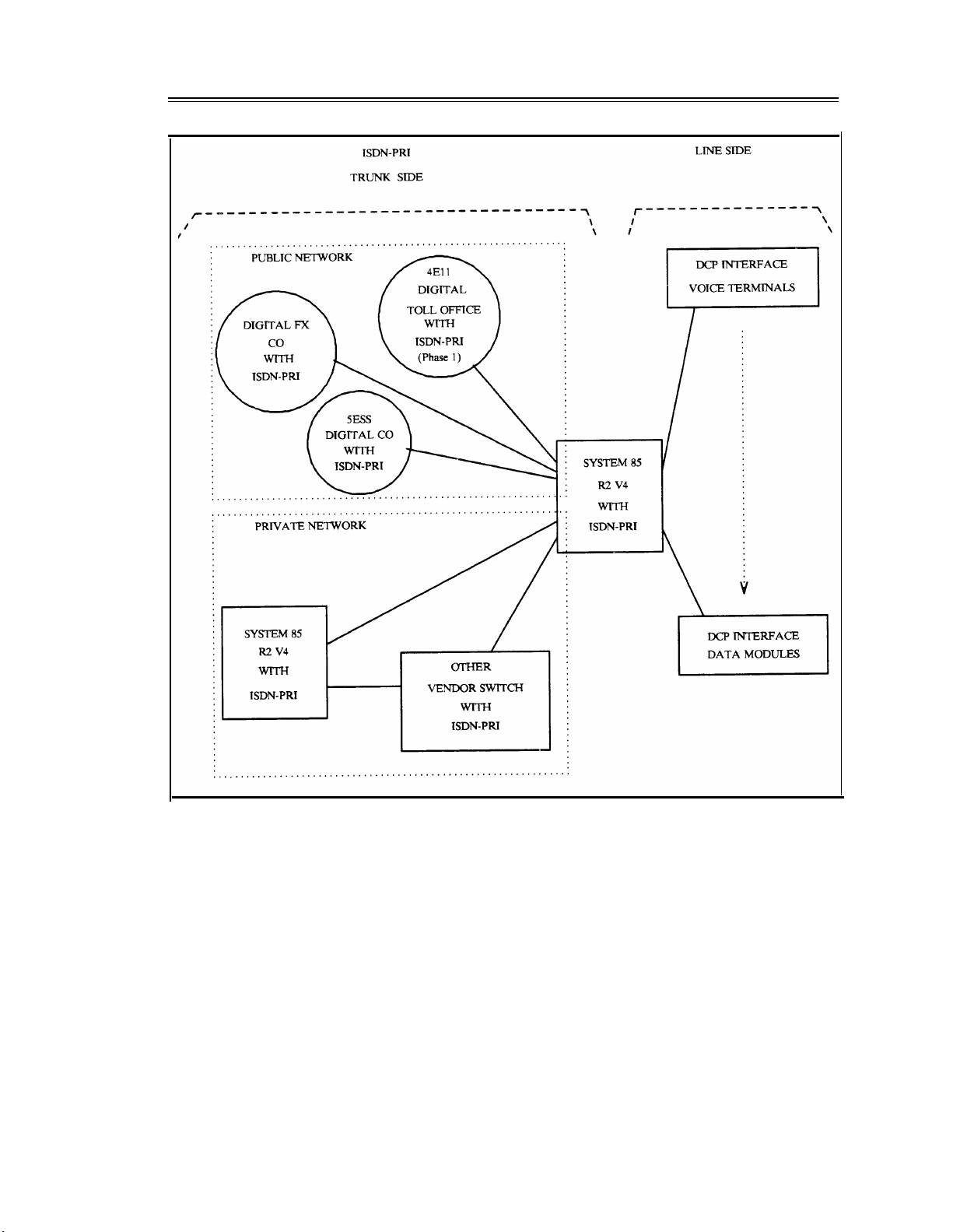
System 85 R2V4 supports ISDN-PRI but not ISDN-BRI. However, System 85 R2V4 uses the lineside digital communications protocol (DCP) to provide end-to-end digital connectivity. The DCP
channel structure consists of 2I + 1S channel format. Each I-channel provides a 64K-bps
information (voice/data) channel, while the S-channel provides an 8K-bps signaling channel. The
DCP is similar to ISDN-BRI, both in structure and in function. The DCP was AT&T’s early attempt
to offer (what at that time was) the evolving BRI standard. Figure 1-1, System 85 R2V4 ISDN
Configuration, shows various trunk-side and line-side connections to a System 85 R2V4.
INTRODUCTION
1-5
Figure 1-1. System 85 R2V4 ISDN Configuration
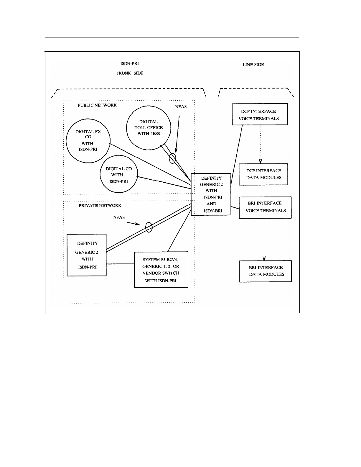
Generic 2 provides a signaling method called nonfacility-associated signaling (NFAS). NFAS allows
a D-channel on one PRI facility (sometimes called a PRI pipe) to provide signaling for B-channels on
another PRI pipe. With NFAS, if two or more PRI pipes are present, an optional D-channel backup
feature is available. One D-channel is administered as the primary D-channel on one DS1 and the
secondary D-channel on another DS1. Only one D-channel per primary-secondary pair can be active
at a time. If the primary D-channel fails, the signaling function is switched automatically to the
secondary (sometimes called the backup) D-channel. Without D-channel backup, D-channel failure
results in loss of service for all calls passing through a PRI pipe.
Generic 2 offers ISDN-BRI, however, some BRI capabilities are not initially available. Figure 1-2,
Generic 2 ISDN Network Configuration, shows a Generic 2 switch in a sample network.
1-6
INTRODUCTION
Figure 1-2. Generic 2 ISDN Network Configuration
Generic 1 and Generic 2 provide ISDN-PRI but do not support wideband channels. Additionally,
ISDN-BRI is not currently supported in Generic 1. However, end-to-end digital connections are
permitted via line-side DCP-interface voice terminals and DCP-interface data modules. Figure 1-3,
Generic 1 ISDN Network Configuration, shows a Generic 1 in a sample network.
Loading...