


Installation Manual
for Cisco IPTV
Receivers
for use with your AT&T U-verse TV service
Model ISB7005
2
Contents |
|
Notice for Installers .......................................................................................................... |
4 |
IMPORTANT SAFETY INSTRUCTIONS.............................................................................. |
4 |
Change the Way You Watch TV ....................................................................................... |
7 |
What’s In the Carton? ...................................................................................................... |
7 |
Safety First....................................................................................................................... |
7 |
Identify Your Receiver with the Serial Number ................................................................. |
7 |
In This Manual .................................................................................................................. |
7 |
Questions About Your Service. ........................................................................................ |
7 |
Protecting You and the Environment ................................................................................ |
7 |
Front Panel....................................................................................................................... |
8 |
Back Panel ....................................................................................................................... |
9 |
Connecting the Receiver................................................................................................ |
10 |
ISB7005 Wireless Network Connection ......................................................................... |
11 |
Connecting the Wireless Access Point to the Wireless Gateway........................................ |
12 |
Pairing the Wireless Access Point and Receiver ............................................................ |
12 |
Connections for a High-Definition TV (HDTV) ................................................................ |
13 |
Connections for a Standard-Definition TV (SDTV) ......................................................... |
14 |
Connections for a VCR or DVD Recorder....................................................................... |
15 |
Connecting an Over-the-Air Converter Box................................................................... |
15 |
Connecting to an HDTV with an HDMI Connector .......................................................... |
16 |
Connecting to an HDTV with a DVI Connector ............................................................... |
17 |
Connecting to an HDTV with Component (YPbPr) Connectors...................................... |
18 |
Connecting to an SDTV with Component (YPbPr) Connectors ...................................... |
19 |
Connecting to an SDTV with an S-Video Connector...................................................... |
20 |
Connecting to an SDTV with an RCA-Type Connector .................................................. |
21 |
Connecting to an SDTV with a Coaxial Cable................................................................. |
22 |
Connecting to a Home Theater System with Component (YPbPr) Connectors ............. |
23 |
Connecting to a Stereo VCR or DVD Recorder (optional) .............................................. |
24 |
Troubleshooting ............................................................................................................. |
25 |
Avoid Screen Burn-In..................................................................................................... |
25 |
Frequently Asked Questions .......................................................................................... |
26 |
Picture Formats.............................................................................................................. |
27 |
Index .............................................................................................................................. |
28 |
Compliance Information ................................................................................................. |
30 |
3

Notice for Installers
The servicing instructions in this notice are for use by qualified service personnel only. To reduce the risk of electric shock, do not perform any servicing other than that contained in the operating instructions, unless you are qualified to do so.
Note to System Installer
For this apparatus, the cable shield/screen shall be grounded as close as practical to the point of entry of the cable into the building. For products sold in the US and Canada, this reminder is provided to call the system installer's attention to Article 800-93 and Article 800-100 of the NEC (or Canadian Electrical Code Part 1), which provides guidelines for proper grounding of the cable shield.
CAUTION: To reduce the risk of electric shock, do not remove cover (or back). No user-serviceable parts inside. Refer servicing to qualified service personnel.
WARNING
TO PREVENT FIRE OR ELECTRIC SHOCK, DO NOT EXPOSE THIS UNIT TO RAIN OR MOISTURE.
This symbol is intended to alert you that uninsulated voltage within this product may have sufficient magnitude to cause electric shock.Therefore, it is dangerous to make any kind of contact with any inside part of this product.
Ce symbole a pour but d’alerter toute personne qu’un contact avec une pièce interne de ce produit, sous tension et non isolée, pourrait être suffisant pour provoquer un choc électrique. Il est donc dangereux d’être en contact avec toute pièce interne de ce produit.
This symbol is intended to alert you of the presence of important operating and maintenance (servicing) instructions in the literature accompanying this product.
Ce symbole a pour but de vous avertir qu’une documentation importante sur le fonctionnement et l’entretien accompagne ce produit.
20080814_Installer800
IMPORTANT SAFETY INSTRUCTIONS
1)Read these instructions.
2)Keep these instructions.
3)Heed all warnings.
4)Follow all instructions.
5)Do not use this apparatus near water.
6)Clean only with dry cloth.
7)Do not block any ventilation openings. Install in accordance with the manufacturer’s instructions.
8)Do not install near any heat sources such as radiators, heat registers, stoves, or other apparatus (including amplifiers) that produce heat.
9)Do not defeat the safety purpose of the polarized or grounding-type plug. A polarized plug has two blades with one wider than the other. A grounding-type plug has two blades and a third grounding prong. The wide blade or the third prong are provided for your safety. If the provided plug does not fit into your outlet, consult an electrician for replacement of the obsolete outlet.
10)Protect the power cord from being walked on or pinched particularly at plugs, convenience receptacles, and the point where they exit from the apparatus.
11)Only use attachments/accessories specified by the manufacturer.
12) |
Use only with the cart, stand, tripod, bracket, or |
|
table specified by the manufacturer, or sold with |
 the apparatus. When a cart is used, use caution when moving the cart/apparatus combination to avoid injury from tip-over.
13)Unplug this apparatus during lightning storms or when unused for long periods of time.
14)Refer all servicing to qualified service personnel. Servicing is required when the apparatus has been damaged in any way, such as a power-supply cord or plug is damaged, liquid has been spilled or objects have fallen into the apparatus, the apparatus has been exposed to rain or moisture, does not operate normally, or has been dropped.
Power Source Warning
A label on this product indicates the correct power source for this product. Operate this product only from an electrical outlet with the voltage and frequency indicated on the product label. If you are uncertain of the type of power supply to your home or business, consult your service provider or your local power company.
The AC inlet on the unit must remain accessible and operable at all times.
Ground the Product
 WARNING: Avoid electric shock and fire hazard! If this product connects to cable wiring, be sure the cable system is grounded (earthed). Grounding provides some protection against voltage surges and built-up static charges.
Protect the Product from Lightning
In addition to disconnecting the AC power from the wall outlet, disconnect the signal inputs.
4

IMPORTANT SAFETY INSTRUCTIONS, continued
Verify the Power Source from the On/Off Power Light
When the on/off power light is not illuminated, the apparatus may still be connected to the power source. The light may go out when the apparatus is turned off, regardless of whether it is still plugged into an AC power source.
Eliminate AC Power/Mains Overloads
 WARNING: Avoid electric shock and fire hazard! Do not overload AC power/mains, outlets, extension cords, or integral convenience receptacles. For products that require battery power or other power sources to operate them, refer to the operating instructions for those products.
Provide Ventilation and
Select a Location
•Remove all packaging material before applying power to the product.
•Do not place this apparatus on a bed, sofa, rug, or similar surface.
•Do not place this apparatus on an unstable surface.
•Do not place this apparatus in excessive heat or moisture.
•Do not install this apparatus in an enclosure, such as a bookcase or rack, unless the installation provides proper ventilation.
•Do not place entertainment devices (such as VCRs or DVDs), lamps, books, vases with liquids, or other objects on top of this product.
•Do not block ventilation openings.
Service Warnings
 WARNING: Avoid electric shock! Do not open the cover of this product. Opening or removing the cover may expose you to dangerous voltages. If you open the cover, your warranty will be void. This product contains no user-serviceable parts.
Check Product Safety
Upon completion of any service or repairs to this product, the service technician must perform safety checks to determine that this product is in proper operating condition.
Protect the Product When Moving It
Always disconnect the power source when moving the apparatus or connecting or disconnecting cables.
20110316_IP_No Tuner_Safety
Operating Environment
This product is designed for operation indoors with a temperature range from 32° to 104° F (0° to 40°C). Each product should have adequate spacing on all sides so that the cooling air vents on the chassis are not blocked.
Protect from Exposure to Moisture and Foreign Objects
 WARNING: Avoid electric shock and fire hazard! Do not expose this product to dripping or splashing liquids, rain, or moisture. Objects filled with liquids, such as vases, should not be placed on this apparatus.
 WARNING: Avoid electric shock and fire hazard! Unplug this product before cleaning. Do not use a liquid cleaner or an aerosol cleaner. Do not use a magnetic/static cleaning device (dust remover) to clean this product.
 WARNING: Avoid electric shock and fire hazard! Never push objects through the openings in this product. Foreign objects can cause electrical shorts that can result in electric shock or fire.
5
6
Change the Way You Watch TV
Welcome to U-verse TV. The ISB7005 devices, known as U-verse receivers, bring a rich, new set of interactive services directly to you through your TV and your in-home IP network. The receiver uses wireless technology 802.11n to connect to the network.
The ISB7005 receiver allows for easy and secure connection to U-verse services. The signal strength indicator on the front panel of the receiver identifies the strength of the wireless connection and aids in the proper placement of the receiver.
What’s In the Carton?
In addition to this installation manual, the receiver carton contains the following items:
•An ISB7005 Receiver - A wireless receiver
•A power cord and power adapter
To support the wireless functionality of the ISB7005 receiver, you will also need a wireless access point that is packaged separately from your receiver. See page 12 of this guide for more information on the wireless access point.
Safety First
Before using the receiver, read the Important Safety Instructions section of this manual.
Identify Your Receiver with the Serial Number
At times your service provider may ask for the serial number. To find the serial number for your receiver, look on the bottom of the receiver for the label. The serial number is a 9-digit numeric code to the right of the letters “S/N” on the label.
Use the space provided here to record the serial number: _______________________________
In This Manual
This manual covers the information you need to connect your receiver to both your in-home IP network and your entertainment system. The manual also outlines certain safeguards and installation information. The safety information contained in this manual was developed and provided solely by the receiver manufacturer, Cisco Systems, Inc.
Questions About Your Service
For questions about how to operate your receiver, once installed, refer to your Feature Guide available for download at: att.com/userguides. For all other questions about your TV service, contact your service provider.
Protecting You and the Environment
Cisco addresses the environmental impact of networking products throughout their lifecycle, from product development, manufacturing, and use to service and end-of-life. Integrating environmental policies into Cisco engineering and manufacturing practices results in socially accountable business practices that help reduce the environmental impact associated with networking products.
7
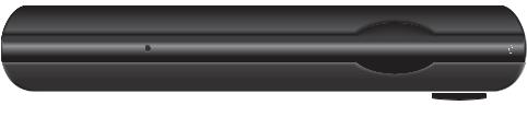
Front Panel
POWER |
LINK |
HD |
RECORD |
MENU |
OK |
ISB7005 |
|
|
|
|
|
1 |
2 |
3 |
4 |
5 |
6 |
7 |
8 |
9 |
10 |
11 |
T14820 |
1 |
Power |
|
Turns the receiver on or places it in standby. To restart the receiver, |
||||||||
|
|
|
press and hold the POWER button for 10 seconds. The LED is green |
||||||||
2 |
Model Number |
Identifies the model number of your receiver as ISB7005 |
|
|
|||||||
3Signal Strength Identifies the strength of the wireless connection
Indicator
4 |
Link |
Indicates network link status. The LED is green |
5 |
HD |
Indicates the set-top is set to a resolution of 720p, 1080i, or 1080p. |
|
|
The LED is blue |
6 |
Record |
Indicates that a recording is in progress. The LED is red |
7 |
IR Sensor |
Receives the infrared signal from the remote control. The sensor is |
|
|
behind the front panel |
8 |
Menu |
Accesses the on-screen menu |
9 |
Arrow Keys |
Accesses on-screen services (such as the on-screen guide, video-on- |
|
|
demand, or pay-per-view) and navigates menus |
10 |
OK |
Selects the current item |
11 |
USB Port |
USB connector. (Reserved for future use) |
Note: This illustration may vary from the actual product.
8
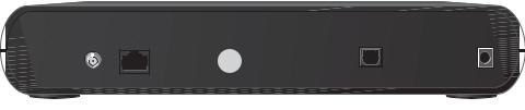
Back Panel
TO TV
(VIDEO OUT)
Pb |
Y |
Pr |
S-VIDEO |
NETWORK |
L |
R |
VIDEO |
AUDIO |
OUT |
OUT |
OPTICAL |
USB |
POWER |
T14821 |
1 |
2 |
3 |
4 |
5 |
6 |
7 |
8 |
9 |
10 |
|
1 |
To TV (Video Out) |
|
Connect to TV. You must set the channel on your TV to the channel |
||||||||
|
|
|
|
designated by your service provider (usually channel 3). Contact your |
|||||||
|
|
|
|
service provider for the channel information |
|
|
|
||||
2 |
Network |
|
|
Connect to the Ethernet (CAT-5) network at your home, if applicable |
|||||||
3 |
YPbPr |
|
|
Connect the receiver to the component video input (YPbPr) on the |
|||||||
|
|
|
|
HDTV. See pages 13 and 14 for more information |
|
|
|
||||
4 |
S-Video |
|
|
Connect an S-Video cable to send an S-Video signal to your TV, VCR, or |
|||||||
|
|
|
|
DVD recorder. This signal is standard-definition but higher quality than |
|||||||
|
|
|
|
other standard-definition TV connections. See page 14 for more |
|||||||
|
|
|
|
information |
|
|
|
|
|
|
|
5 |
Video Out |
|
|
Connect to composite input on your HDTV or SDTV |
|
|
|||||
|
|
|
|
Note: Two video output connectors are provided. Typically, one output |
|||||||
|
|
|
|
is connected to the TV, and the other output is used to connect to a |
|||||||
|
|
|
|
home theater system, DVD recorder, or VCR |
|
|
|
||||
6 |
Audio Out (L/R) |
|
Connect RCA-type cables to Audio Out to send analog audio signals |
||||||||
|
|
|
|
(left and right) to a TV with stereo inputs or to a stereo amplifier |
|||||||
|
|
|
|
Note: Two sets of audio out connectors are provided. Typically, one set |
|||||||
|
|
|
|
of outputs is connected to the TV, and the other set is used to connect |
|||||||
|
|
|
|
to a home theater system, DVD recorder, or VCR |
|
|
|
||||
7 |
Optical |
|
|
Connect an optical cable to send a digital audio signal to a surround- |
|||||||
|
|
|
|
sound receiver or other digital audio device |
|
|
|
||||
8 |
HDMI |
|
|
Connect an HDTV HDMI™ (High-Definition Multimedia Interface) cable |
|||||||
|
|
|
|
from the HDTV to the HDMI port. HDMI supports both digital audio and |
|||||||
|
|
|
|
video. See page 13 for more information |
|
|
|
|
|||
9 |
USB Port |
|
|
USB connector. (Reserved for future use) |
|
|
|
||||
10 |
Power |
|
|
Connect the DC output of the AC power adapter (provided) to deliver |
|||||||
|
|
|
|
power to the receiver |
|
|
|
|
|
|
|
Note: This illustration may vary from the actual product.
9
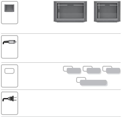
Connecting the Receiver
To connect your receiver to your network and home entertainment devices, complete these steps.
|
Because the connections |
|
|
|
|
for a high-definition (HD) |
16 |
|
4 |
|
or standard-definition (SD) |
9 |
or |
3 |
1 |
TV are different, you must |
|||
determine if your TV is HD |
|
|
|
|
or SD. Your TV must |
|
|
|
|
receive HD signals for |
|
|
|
|
you to enjoy the benefits |
|
|
|
of HDTV. Refer to the manual that came with your TV for more information. See page 27 for more information on picture formats.
Make the connections for your TV, VCR, and DVD recorder as follows:
|
• If you are using an HDTV, see page 13 and the connection diagrams in this |
|||
2 |
manual. |
|
|
|
• If you are using a standard-definition TV, see page 14 and the connection |
||||
diagrams in this manual. |
|
|
|
|
• If you want to record some programs on VCR tape or DVD, see page 15 |
||||
|
and the connection diagrams in this manual. |
|
|
|
|
Identify the additional consumer |
|
|
|
|
electronic devices you will |
VCR |
DVD |
Other |
|
connect to the receiver and TV. |
|||
3 |
|
|
See pages 16 through 24 and |
|
|
|
refer to the owner’s manual for |
|
|
the device. |
Home Theater |
|
|
|
Plug the receiver and the TV into an AC power source that is not controlled by a switch. For further instructions on completing your setup, refer to the Feature Guide available from your service provider.
4
10
 Loading...