


Copyright Notice:
No part of this installation guide may be reproduced, transcribed, transmitted, or translated in any language, in any form or by any means, except duplication of documentation by the purchaser for backup purpose, without written consent of ASRock Inc.
Products and corporate names appearing in this guide may or may not be registered trademarks or copyrights of their respective companies, and are used only for identification or explanation and to the owners’ benefit, without intent to infringe.
Disclaimer:
Specifications and information contained in this guide are furnished for informational use only and subject to change without notice, and should not be constructed as a commitment by ASRock. ASRock assumes no responsibility for any errors or omissions that may appear in this guide.
With respect to the contents of this guide, ASRock does not provide warranty of any kind, either expressed or implied, including but not limited to the implied warranties or conditions of merchantability or fitness for a particular purpose. In no event shall ASRock, its directors, officers, employees, or agents be liable for any indirect, special, incidental, or consequential damages (including damages for loss of profits, loss of business, loss of data, interruption of business and the like), even if ASRock has been advised of the possibility of such damages arising from any defect or error in the guide or product.
This device complies with Part 15 of the FCC Rules. Operation is subject to the following two conditions:
(1)this device may not cause harmful interference, and
(2)this device must accept any interference received, including interference that may cause undesired operation.
CALIFORNIA, USA ONLY
The Lithium battery adopted on this motherboard contains Perchlorate, a toxic substance controlled in Perchlorate Best Management Practices (BMP) regulations passed by the California Legislature. When you discard the Lithium battery in California, USA, please follow the related regulations in advance.
“Perchlorate Material-special handling may apply, see www.dtsc.ca.gov/hazardouswaste/perchlorate”
ASRock Website: http://www.asrock.com
Published July 2011
Copyright©2011 ASRock INC. All rights reserved.
1
English
ASRock Z68 Extreme3 Gen3 Motherboard

English
Motherboard Layout |
|
|
|
|
|
|
|
|
|
|
|||||||||
|
|
|
|
|
|
|
|
1 |
|
2 |
3 |
4 |
|
|
5 |
|
6 |
|
|
|
|
|
|
|
|
|
|
21.8cm (8.6 in) |
|
|
|
|
|
|
|
|
|
|
|
|
Keyboard |
PS2 |
USB 2.0 |
|
|
|
|
PWR_FAN1 |
|
|
|
|
|
|
|
7 |
|||
|
|
|
|
T: USB0 |
|
|
|
|
|
|
|
|
|
|
|
|
|
||
|
|
|
|
B: USB1 |
|
|
|
|
|
|
|
|
|
|
|
|
|||
|
|
|
|
|
|
|
|
ATX12V1 |
|
|
|
|
|
|
|
|
|
|
|
|
|
|
VGA1 |
|
DVI CON1 |
|
|
|
|
|
|
DX10.1 |
DDR32133 |
pin-240module) |
pin-240module) |
pin-240module) |
pin-240module) |
|
in) |
|
Clr CMOS |
|
|
|
|
|
|
|
|
|
|
|
30.5cm(12.0 |
||||||
|
HDMI1 |
|
|
|
|
|
|
|
|
|
|
ReadyErP/EuP |
bit,(64A1DDR3 |
bit,(64A2DDR3 |
bit,(64B1DDR3 |
bit,(64B2DDR3 |
ATXPWR1 |
|
|
|
eSATA |
|
|
T: USB2 |
|
|
|
|
|
|
|
||||||||
|
|
|
|
USB 2.0 |
|
|
|
|
|
|
|
|
|
|
|
|
|
||
|
1_ |
|
|
B: USB3 |
|
|
|
|
|
|
|
|
|
|
|
|
|
||
|
|
|
|
|
|
|
|
|
|
|
|
|
|
|
|
|
|
|
8 |
|
USB 3.0 |
|
Top: |
|
|
|
|
|
|
|
|
|
|
|
|
||||
|
T: USB4 |
|
|
|
|
|
|
|
|
|
|
|
|
|
|||||
|
B: USB5 |
|
RJ-45 |
|
|
|
|
|
|
|
|
|
|
|
|
||||
|
SPDIF |
Optical |
Bottom: |
REARSPK |
Center: |
Central/Bass |
Top: |
|
|
|
|
|
|
|
|
|
|
|
|
|
MICIN |
Bottom: |
|
FRONT |
Center: |
LINEIN |
Top: |
|
|
|
|
|
|
|
|
|
|
|
|
41 |
|
|
|
|
|
|
|
|
|
|
|
|
|
|
|
|
|
|
9 |
|
|
|
|
|
|
|
LAN |
USB 3.0 |
|
|
|
|
|
|
|
|
|
|
|
|
|
|
|
|
|
|
PHY |
HDMI 1.4a |
|
|
XFast USB |
|
|
|
|
|
|
||
40 |
|
|
|
|
|
|
|
PCIE1 |
|
|
|
|
|
|
|
|
|||
|
|
|
|
|
AUDIO |
|
PCI Express 3.0 |
Z68 Extreme3 Gen3 |
|
|
|
|
|
|
|
|
|||
|
|
|
|
|
CODEC |
|
|
|
|
|
|
|
|
|
|
|
|
|
|
39 |
|
|
|
|
|
|
|
|
PCIE2 |
|
|
|
Intel |
|
|
|
10 |
||
|
|
|
|
|
|
|
|
|
|
|
|
|
|
|
|
|
|||
|
|
|
|
|
|
|
|
|
CMOS |
|
|
|
|
Z68 |
|
|
|
11 |
|
38 |
|
|
|
|
|
|
|
PCIE3 |
Battery |
|
|
|
|
|
1 |
|
|
||
|
|
|
|
|
|
|
|
|
|
|
|
|
|
|
_ |
|
|
||
|
|
|
|
|
|
|
|
|
|
|
|
|
|
|
|
0 |
|
12 |
|
|
|
|
|
|
|
|
|
|
|
|
|
|
|
|
|
|
SATA3 |
|
|
|
|
|
|
|
|
|
Super |
|
|
|
|
|
|
|
|
|
|
|
|
|
|
|
|
|
|
|
I/O |
|
|
|
|
|
|
|
|
|
|
|
13 |
|
|
|
|
|
|
|
|
|
|
|
|
|
|
|
|
|
2 3 |
|
|
37 |
|
|
|
|
|
|
|
PCI1 |
|
|
|
|
|
|
|
|
|
||
|
|
|
|
|
|
|
SATA3 6Gb/s |
|
|
|
|
|
|
|
SATA2 |
|
14 |
||
|
|
|
|
|
|
|
|
|
|
|
|
|
|
|
|
||||
36 |
inTaipei |
|
|
|
|
|
|
|
|
|
|
|
|
|
|
5 |
|
15 |
|
|
|
|
|
|
|
PCIE4 |
|
|
1 |
|
|
|
|
SATA24_ |
|
16 |
|||
|
Designed |
|
|
|
|
|
|
|
|
CLRCMOS1 |
|
|
|
|
|
||||
|
|
|
|
|
|
RoHS |
|
|
|
|
|
|
Dr. |
|
PLED1 |
|
17 |
||
|
|
|
|
|
|
|
|
|
|
|
|
|
|
Debug |
|
|
RSTBTN |
||
35 |
|
|
|
|
|
|
|
PCI2 |
|
|
|
|
|
1 |
1 |
|
|
18 |
|
|
|
|
|
|
|
HDMI_SPDIF1 |
|
|
|
|
|
|
|
|
|
|
|||
|
|
|
|
|
|
|
1 |
|
|
|
|
|
|
|
|
PANEL1 |
|
PWRBTN |
19 |
|
|
|
|
|
|
|
COM1 |
|
USB8_9 |
USB10_11 |
USB12_13 |
|
|
64Mb |
|
|
|||
|
|
1 |
HD_AUDIO1 |
|
IR1 |
|
|
|
|
|
|
|
1 |
|
|
||||
|
|
|
|
|
|
1 |
|
1 |
|
|
|
|
|
BIOS |
|
|
|
||
|
|
|
|
|
|
|
|
1 |
1 |
1 |
1 |
|
|
|
|
|
|
|
|
34 33 32 31 30 29 28 27 26 25 24 23 22 21 20
1 |
ATX 12V Power Connector (ATX12V1) |
22 |
64Mb SPI Flash |
2 |
1155-Pin CPU Socket |
23 |
Chassis Fan Connector (CHA_FAN1) |
3 |
Power Fan Connector (PWR_FAN1) |
24 |
Dr. Debug |
4 |
CPU Fan Connector (CPU_FAN1) |
25 |
USB 2.0 Header (USB12_13, Black) |
5 |
2 x 240-pin DDR3 DIMM Slots |
26 |
Clear CMOS Jumper (CLRCMOS1) |
|
(Dual Channel: DDR3_A1, DDR3_B1, Black) |
27 |
USB 2.0 Header (USB10_11, Black) |
6 |
2 x 240-pin DDR3 DIMM Slots |
28 |
USB 2.0 Header (USB8_9, Black) |
|
(Dual Channel: DDR3_A2, DDR3_B2, Black) |
29 |
USB 2.0 Header (USB6_7, Black) |
7 |
CPU Fan Connector (CPU_FAN2) |
30 |
Consumer Infrared Module Header |
8 |
ATX Power Connector (ATXPWR1) |
|
(CIR1, Gray) |
9 |
Chassis Fan Connector (CHA_FAN2) |
31 |
COM Port Header (COM1) |
10 |
Intel Z68 Chipset |
32 |
HDMI_SPDIF Header |
11 |
SATA3 Connector (SATA3_1, Gray) |
|
(HDMI_SPDIF1, Black) |
12 |
SATA3 Connector (SATA3_0, Gray) |
33 |
Infrared Module Header (IR1) |
13 |
SATA2 Connector (SATA2_3, Black) |
34 |
Front Panel Audio Header |
14 |
SATA2 Connector (SATA2_2, Black) |
|
(HD_AUDIO1, Black) |
15 |
SATA2 Connector (SATA2_5, Black) |
35 |
PCI Slot (PCI2) |
16 |
SATA2 Connector (SATA2_4, Black) |
36 |
PCI Express 3.0 x16 Slot (PCIE4, Black) |
17 |
Reset Switch (RSTBTN) |
37 |
PCI Slot (PCI1) |
18 |
Power LED Header (PLED1) |
38 |
PCI Express 2.0 x1 Slot (PCIE3, Black) |
19 |
Power Switch (PWRBTN) |
39 |
PCI Express 3.0 x16 Slot (PCIE2, Black) |
20 |
System Panel Header (PANEL1, Black) |
40 |
PCI Express 2.0 x1 Slot (PCIE1, Black) |
21 |
Chassis Speaker Header (SPEAKER 1, Black) |
41 |
Chassis Fan Connector (CHA_FAN3) |
2
ASRock Z68 Extreme3 Gen3 Motherboard
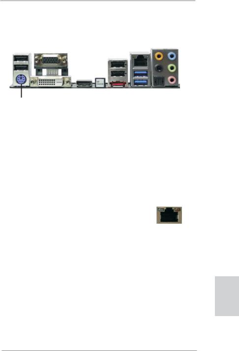
I/O Panel
|
1 |
2 |
|
|
|
3 |
4 |
|
|
|
|
|
|
|
|
|
|
|
|||
|
|
|
|
|
|
|
|
|
|
|
|
|
|
|
|
5 |
|
|
8 |
||
|
|
|
|
|
|
|
|
|
|
|
|
|
|
||||||||
|
|
|
|
|
|
|
|
|
|
|
|
||||||||||
|
|
|
|
|
|
|
|
|
|
|
|
|
|
|
|
|
|||||
|
|
|
|
|
|
|
|
|
|
|
|
|
|
|
|
|
6 |
|
|
|
9 |
|
|
|
|
|
|
|
|
|
|
|
|
|
|
|
|
|
|
|
|
||
|
|
|
|
|
|
|
|
|
|
|
|
|
|
|
|
|
|
|
|
||
|
|
|
|
|
|
|
|
|
|
|
|
|
|
|
|
|
|||||
|
|
|
|
|
|
|
|
|
|
|
|
|
|
|
|
7 |
|
|
10 |
||
|
|
|
|
|
|
|
|
|
|
|
|
|
|
|
|
|
|||||
|
|
|
|
|
|
|
|
|
|
|
|
|
|
|
|
|
|||||
|
|
|
|
|
|
|
|
|
|
|
|
|
|
|
|||||||
|
|
|
|
|
|
|
|
|
|
|
|
|
|
|
|
|
|
|
|
|
|
|
|
|
|
|
|
|
|
|
|
|
|
|
|
|
|
|
|
|
|
|
|
|
16 |
15 |
14 |
13 |
12 |
11 |
1 |
USB 2.0 Ports (USB01) |
|
|
** 9 |
Front Speaker (Lime) |
|
2 |
D-Sub Port (VGA1) |
|
|
10 |
Microphone (Pink) |
|
3 |
USB 2.0 Ports (USB23) |
|
|
11 |
USB 3.0 Ports (USB45) |
|
* 4 |
LAN RJ-45 Port |
|
|
*** 12 |
eSATA3 Connector |
|
5 |
Central / Bass (Orange) |
|
|
13 |
Clear CMOS Switch (CLRCBTN) |
|
6 |
Rear Speaker (Black) |
|
|
14 |
HDMI Port (HDMI1) |
|
7 |
Optical SPDIF Out Port |
|
|
15 |
DVI-D Port (DVI1) |
|
8 |
Line In (Light Blue) |
|
|
16 |
PS/2 Keyboard Port (Purple) |
|
*There are two LED next to the LAN port. Please refer to the table below for the LAN port LED indications.
LAN Port LED Indications
Activity/Link LED |
|
SPEED LED |
ACT/LINK |
SPEED |
|||||
|
LED |
LED |
|||||||
|
|
|
|
|
|
||||
Status |
Description |
|
Status |
|
Description |
|
|
|
|
Off |
No Link |
|
Off |
|
10Mbps connection |
|
|
|
|
|
|
|
|
||||||
Blinking |
Data Activity |
|
Orange |
|
100Mbps connection |
|
|
|
|
On |
Link |
|
Green |
|
1Gbps connection |
|
|
|
|
|
|
|
|
|
|
LAN Port |
|||
|
|
|
|
|
|
||||
**If you use 2-channel speaker, please connect the speaker’s plug into “Front Speaker Jack”. See the table below for connection details in accordance with the type of speaker you use.
TABLE for Audio Output Connection
Audio Output Channels |
Front Speaker |
Rear Speaker |
Central / Bass |
Line In or |
|
(No. 9) |
(No. 6) |
(No. 5) |
Side Speaker |
|
|
|
|
(No. 8) |
|
|
|
|
|
2 |
V |
-- |
-- |
-- |
4 |
V |
V |
-- |
-- |
6 |
V |
V |
V |
-- |
8 |
V |
V |
V |
V |
English
3
ASRock Z68 Extreme3 Gen3 Motherboard

To enable Multi-Streaming function, you need to connect a front panel audio cable to the front panel audio header. After restarting your computer, you will find “Mixer” tool on your system. Please select “Mixer ToolBox”  , click “Enable playback multi-streaming”, and click
“ok”. Choose “2CH”, “4CH”, “6CH”, or “8CH” and then you are allowed to select “Realtek HDA Primary output” to use Rear Speaker, Central/Bass, and Front Speaker, or select “Realtek HDA Audio 2nd output” to use front panel audio.
*** eSATA3 connector supports SATA Gen3 in cable 1M.
English
4
ASRock Z68 Extreme3 Gen3 Motherboard

1. Introduction
Thank you for purchasing ASRock Z68 Extreme3 Gen3 motherboard, a reliable motherboard produced under ASRock’s consistently stringent quality control. It delivers excellent performance with robust design conforming to ASRock’s commitment to quality and endurance.
This Quick Installation Guide contains introduction of the motherboard and step-by- step installation guide. More detailed information of the motherboard can be found in the user manual presented in the Support CD.
Because the motherboard specifications and the BIOS software might be updated, the content of this manual will be subject to change without notice. In case any modifications of this manual occur, the updated version will be available on ASRock website without further notice. You may find the latest VGA cards and CPU support lists on ASRock website as well. ASRock website http://www.asrock.com
If you require technical support related to this motherboard, please visit our website for specific information about the model you are using. www.asrock.com/support/index.asp
1.1 Package Contents
ASRock Z68 Extreme3 Gen3 Motherboard
(ATX Form Factor: 12.0-in x 8.6-in, 30.5 cm x 21.8 cm) ASRock Z68 Extreme3 Gen3 Quick Installation Guide ASRock Z68 Extreme3 Gen3 Support CD
2 x Serial ATA (SATA) Data Cables (Optional)
1 x 3.5mm Audio Cable (Optional)
1 x I/O Panel Shield
1 x ASRock SLI_Bridge_2S Card
ASRock Reminds You...
To get better performance in Windows® 7 / 7 64-bit / VistaTM / VistaTM 64bit, it is recommended to set the BIOS option in Storage Configuration to AHCI mode. For the BIOS setup, please refer to the “User Manual” in our support CD for details.
English
5
ASRock Z68 Extreme3 Gen3 Motherboard

English
1.2Specifications
Platform |
- ATX Form Factor: 12.0-in x 8.6-in, 30.5 cm x 21.8 cm |
|
- Premium Gold Capacitor design (100% Japan-made |
|
high-quality Conductive Polymer Capacitors) |
CPU |
- Supports 2nd Generation Intel® CoreTM i7 / i5 / i3 in |
|
LGA1155 Package |
|
- Advanced V8 + 4 Power Phase Design |
|
- Supports Intel® Turbo Boost 2.0 Technology |
|
- Supports K-Series unlocked CPU |
|
- Supports Hyper-Threading Technology (see CAUTION 1) |
Chipset |
- Intel® Z68 |
Memory |
- Dual Channel DDR3 Memory Technology (see CAUTION 2) |
|
- 4 x DDR3 DIMM slots |
|
- Supports DDR3 2133(OC)/1866(OC)/1600/1333/1066 |
|
non-ECC, un-buffered memory (see CAUTION 3) |
|
- Max. capacity of system memory: 32GB (see CAUTION 4) |
|
- Supports Intel® Extreme Memory Profile (XMP) |
Expansion Slot |
- 2 x PCI Express 3.0 x16 slots (PCIE2/PCIE4: single at x16 |
|
(PCIE2) / x8 (PCIE4), or dual at x8 (PCIE2) / x8 (PCIE4)) |
|
(PCI Express 3.0 with Intel® Ivy Bridge CPU, PCI Express 2.0 |
|
with Intel® Sandy Bridge CPU) |
|
- 2 x PCI Express 2.0 x1 slots |
|
- 2 x PCI slots |
|
- Supports AMD Quad CrossFireXTM and CrossFireXTM |
|
- Supports NVIDIA® Quad SLITM and SLITM |
Graphics |
- Supports Intel® HD Graphics Built-in Visuals: Intel® Quick |
|
Sync Video, Intel® InTruTM 3D, Intel® Clear Video HD |
|
Technology, Intel® HD Graphics 2000/3000, Intel® Advanced |
|
Vector Extensions (AVX) |
|
- Pixel Shader 4.1, DirectX 11 with Intel® Ivy Bridge CPU, |
|
DirectX 10.1 with Intel® Sandy Bridge CPU |
|
- Max. shared memory 1759MB (see CAUTION 5) |
|
- Three VGA Output options: D-Sub, DVI-D and HDMI |
|
(see CAUTION 6) |
|
- Supports HDMI 1.4a Technology with max. resolution up to |
|
1920x1200 @ 60Hz |
|
- Supports DVI with max. resolution up to 1920x1200 @ 60Hz |
|
- Supports D-Sub with max. resolution up to 2048x1536 @ |
|
75Hz |
6
ASRock Z68 Extreme3 Gen3 Motherboard

|
- Supports Auto Lip Sync, Deep Color (12bpc), xvYCC and |
|
HBR (High Bit Rate Audio) with HDMI |
|
(Compliant HDMI monitor is required) (see CAUTION 7) |
|
- Supports HDCP function with DVI and HDMI |
|
- Supports Full HD 1080p Blu-ray (BD) / HD-DVD playback |
|
with DVI and HDMI ports |
Audio |
- 7.1 CH HD Audio with Content Protection |
|
(Realtek ALC892 Audio Codec) |
|
- Premium Blu-ray audio support |
|
- Supports THX TruStudioTM |
LAN |
- PCIE x1 Gigabit LAN 10/100/1000 Mb/s |
|
- Realtek RTL8111E |
|
- Supports Wake-On-LAN |
|
- Supports LAN Cable Detection |
|
- Supports Energy Efficient Ethernet 802.3az |
|
- Supports PXE |
Rear Panel I/O |
I/O Panel |
|
- 1 x PS/2 Keyboard Port |
|
- 1 x D-Sub Port |
|
- 1 x DVI-D Port |
|
- 1 x HDMI Port |
|
- 1 x Optical SPDIF Out Port |
|
- 4 x Ready-to-Use USB 2.0 Ports |
|
- 1 x eSATA3 Connector |
|
- 2 x Ready-to-Use USB 3.0 Ports |
|
- 1 x RJ-45 LAN Port with LED (ACT/LINK LED and SPEED |
|
LED) |
|
- 1 x Clear CMOS Switch with LED |
|
- HD Audio Jack: Rear Speaker/Central/Bass/Line in/Front |
|
Speaker/Microphone (see CAUTION 8) |
SATA3 |
- 2 x SATA3 6.0 Gb/s connectors, support RAID (RAID 0, |
|
RAID 1, RAID 10, RAID 5, Intel Rapid Storage and Intel |
|
Smart Response Technology), NCQ, AHCI and “Hot Plug” |
|
functions (SATA3_1 connector is shared with eSATA3 port) |
USB3.0 |
- 2 x USB 3.0 ports by ASMedia ASM1042, support |
|
USB 1.0/2.0/3.0 up to 5Gb/s |
Connector |
- 4 x SATA2 3.0 Gb/s connectors, support RAID (RAID 0, |
|
RAID 1, RAID 10, RAID 5, Intel Rapid Storage and Intel |
|
Smart Response Technology), NCQ, AHCI and Hot Plug |
|
functions |
7
English
ASRock Z68 Extreme3 Gen3 Motherboard

English
|
- 2 x SATA3 6.0Gb/s connectors |
|
- 1 x IR header |
|
- 1 x CIR header |
|
- 1 x COM port header |
|
- 1 x HDMI_SPDIF header |
|
- 1 x Power LED header |
|
- CPU/Chassis/Power FAN connector |
|
- 24 pin ATX power connector |
|
- 8 pin 12V power connector |
|
- Front panel audio connector |
|
- 4 x USB 2.0 headers (support 8 USB 2.0 ports) |
|
- 1 x Dr. Debug (7-Segment Debug LED) |
Smart Switch |
- 1 x Clear CMOS Switch with LED |
|
- 1 x Power Switch with LED |
|
- 1 x Reset Switch with LED |
BIOS Feature |
- 64Mb AMI BIOS |
|
- AMI UEFI Legal BIOS with GUI support |
|
- Supports “Plug and Play” |
|
- ACPI 1.1 Compliance Wake Up Events |
|
- Supports jumperfree |
|
- SMBIOS 2.3.1 Support |
|
- CPU Core, IGPU, DRAM, PCH, CPU PLL, VTT, VCCSA |
|
Voltage Multi-adjustment |
Support CD |
- Drivers, Utilities, AntiVirus Software (Trial Version), |
|
CyberLink MediaEspresso 6.5 Trial, ASRock Software Suite |
|
(CyberLink DVD Suite - OEM and Trial; ASRock MAGIX |
|
Multimedia Suite - OEM) |
Unique Feature |
- ASRock Extreme Tuning Utility (AXTU) (see CAUTION 9) |
|
- ASRock Instant Boot |
|
- ASRock Instant Flash (see CAUTION 10) |
|
- ASRock APP Charger (see CAUTION 11) |
|
- ASRock SmartView (see CAUTION 12) |
|
- ASRock XFast USB (see CAUTION 13) |
|
- ASRock XFast LAN (see CAUTION 14) |
|
- Lucid Virtu (see CAUTION 15) |
|
- ASRock On/Off Play Technology (see CAUTION 16) |
|
- Hybrid Booster: |
|
- CPU Frequency Stepless Control (see CAUTION 17) |
|
- ASRock U-COP (see CAUTION 18) |
|
- Boot Failure Guard (B.F.G.) |
|
- Combo Cooler Option (C.C.O.) (see CAUTION 19) |
|
- Good Night LED |
8
ASRock Z68 Extreme3 Gen3 Motherboard

Hardware |
- CPU Temperature Sensing |
Monitor |
- Chassis Temperature Sensing |
|
- CPU/Chassis/Power Fan Tachometer |
|
- CPU/Chassis Quiet Fan (Allow Chassis Fan Speed |
|
Auto-Adjust by CPU Temperature) |
|
- CPU/Chassis Fan Multi-Speed Control |
|
- Voltage Monitoring: +12V, +5V, +3.3V, CPU Vcore |
OS |
- Microsoft® Windows® 7 / 7 64-bit / VistaTM / VistaTM 64-bit |
|
/ XP / XP 64-bit compliant |
Certifications |
- FCC, CE, WHQL |
|
- ErP/EuP Ready (ErP/EuP ready power supply is required) |
|
(see CAUTION 20) |
* For detailed product information, please visit our website: http://www.asrock.com
WARNING
Please realize that there is a certain risk involved with overclocking, including adjusting the setting in the BIOS, applying Untied Overclocking Technology, or using the third-party overclocking tools. Overclocking may affect your system stability, or even cause damage to the components and devices of your system.
It should be done at your own risk and expense. We are not responsible for possible damage caused by overclocking.
English
9
ASRock Z68 Extreme3 Gen3 Motherboard

English
10
CAUTION!
1.About the setting of “Hyper Threading Technology”, please check page
60of “User Manual” in the support CD.
2.This motherboard supports Dual Channel Memory Technology. Before you implement Dual Channel Memory Technology, make sure to read the installation guide of memory modules on page 16 for proper installation.
3.DDR3 frequency options may depend on the processor. Only K-Series CPU can support DDR3 overclock to 2133 and 1866.
4.Due to the operating system limitation, the actual memory size may be less than 4GB for the reservation for system usage under Windows® 7 / VistaTM / XP. For Windows® OS with 64-bit CPU, there is no such limitation.
5.The maximum shared memory size is defined by the chipset vendor and is subject to change. Please check Intel® website for the latest information.
6.You can choose to use two of the three monitors only. D-Sub, DVI-D and HDMI monitors cannot be enabled at the same time. Besides, with the DVI-to-HDMI adapter, the DVI-D port can support the same features as HDMI port.
7.xvYCC and Deep Color are only supported under Windows® 7 64-bit /
7.Deep Color mode will be enabled only if the display supports 12bpc in EDID. HBR is supported under Windows® 7 64-bit / 7 / VistaTM 64-bit / VistaTM.
8.For microphone input, this motherboard supports both stereo and mono modes. For audio output, this motherboard supports 2-channel, 4-chan- nel, 6-channel, and 8-channel modes. Please check the table on page 3 for proper connection.
9.ASRock Extreme Tuning Utility (AXTU) is an all-in-one tool to fine-tune different system functions in a user-friendly interface, which is including Hardware Monitor, Fan Control, Overclocking, OC DNA and IES. In Hardware Monitor, it shows the major readings of your system. In Fan Control, it shows the fan speed and temperature for you to adjust. In Overclocking, you are allowed to overclock CPU frequency for optimal system performance. In OC DNA, you can save your OC settings as a profile and share with your friends. Your friends then can load the OC profile to their own system to get the same OC settings. In IES (Intelligent Energy Saver), the voltage regulator can reduce the number of output phases to improve efficiency when the CPU cores are idle without sacrificing computing performance. Please visit our website for the operation procedures of ASRock Extreme Tuning Utility (AXTU).
ASRock website: http://www.asrock.com
ASRock Z68 Extreme3 Gen3 Motherboard
10.ASRock Instant Flash is a BIOS flash utility embedded in Flash ROM. This convenient BIOS update tool allows you to update system BIOS without entering operating systems first like MS-DOS or Windows®. With this utility, you can press <F6> key during the POST or press <F2> key to BIOS setup menu to access ASRock Instant Flash. Just launch this tool and save the new BIOS file to your USB flash drive, floppy disk or hard drive, then you can update your BIOS only in a few clicks without preparing an additional floppy diskette or other complicated flash utility. Please be noted that the USB flash drive or hard drive must use FAT32/16/12 file system.
11.If you desire a faster, less restricted way of charging your Apple devices, such as iPhone/iPod/iPad Touch, ASRock has prepared a wonderful solution for you - ASRock APP Charger. Simply installing the APP Charger driver, it makes your iPhone charged much quickly from your computer and up to 40% faster than before. ASRock APP Charger allows you to quickly charge many Apple devices simultaneously and even supports continuous charging when your PC enters into Standby mode (S1), Suspend to RAM (S3), hibernation mode (S4) or power off (S5). With APP Charger driver installed, you can easily enjoy the marvelous charging experience than ever.
ASRock website: http://www.asrock.com/Feature/AppCharger/index.asp
12.SmartView, a new function of internet browser, is the smart start page for IE that combines your most visited web sites, your history, your Facebook friends and your real-time newsfeed into an enhanced view for a more personal Internet experience. ASRock motherboards are exclusively equipped with the SmartView utility that helps you keep in touch with friends on-the-go. To use SmartView feature, please make sure your OS version is Windows® 7 / 7 64 bit / VistaTM / VistaTM 64 bit, and your browser version is IE8. ASRock website: http://www.asrock.com/Feature/ SmartView/index.asp
13.ASRock XFast USB can boost USB storage device performance. The performance may depend on the property of the device.
14.ASRock XFast LAN provides a faster internet access, which includes below benefits. LAN Application Prioritization: You can configure your application priority ideally and/or add new programs. Lower Latency in Game: After setting online game priority higher, it can lower the latency in game. Traffic Shaping: You can watch Youtube HD video and download files simultaneously. Real-Time Analysis of Your Data: With the status window, you can easily recognize which data streams you are currently transferring.
15.With Lucid Virtu technology, you can enjoy benefits from both 3D performance of the discrete GPU and advanced media features of Intel® HD graphics.
English
11
ASRock Z68 Extreme3 Gen3 Motherboard

16.ASRock On/Off Play Technology allows users to enjoy the great audio experience from the portable audio devices, such like MP3 player or mobile phone to your PC, even when the PC is turned off (or in ACPI S5 mode)! This motherboard also provides a free 3.5mm audio cable (optional) that ensures users the most convenient computing environment.
17.Although this motherboard offers stepless control, it is not recommended to perform over-clocking. Frequencies other than the recommended CPU bus frequencies may cause the instability of the system or damage the CPU.
18.While CPU overheat is detected, the system will automatically shutdown. Before you resume the system, please check if the CPU fan on the motherboard functions properly and unplug the power cord, then plug it back again. To improve heat dissipation, remember to spray thermal grease between the CPU and the heatsink when you install the PC system.
19.Combo Cooler Option (C.C.O.) provides the flexible option to adopt three different CPU cooler types, Socket LGA 775, LGA 1155 and LGA 1156. Please be noticed that not all the 775 and 1156 CPU Fan can be used.
20.EuP, stands for Energy Using Product, was a provision regulated by European Union to define the power consumption for the completed system. According to EuP, the total AC power of the completed system shall be under 1.00W in off mode condition. To meet EuP standard, an EuP ready motherboard and an EuP ready power supply are required. According to Intel’s suggestion, the EuP ready power supply must meet the standard of 5v standby power efficiency is higher than 50% under 100 mA current consumption. For EuP ready power supply selection, we recommend you checking with the power supply manufacturer for more details.
English
12
ASRock Z68 Extreme3 Gen3 Motherboard
2. Installation
Pre-installation Precautions
Take note of the following precautions before you install motherboard components or change any motherboard settings.
1.Unplug the power cord from the wall socket before touching any component. Failure to do so may cause severe damage to the motherboard, peripherals, and/or components.
2.To avoid damaging the motherboard components due to static electricity, NEVER place your motherboard directly on the carpet or the like. Also remember to use a grounded wrist strap or touch a safety grounded object before you handle components.
3.Hold components by the edges and do not touch the ICs.
4.Whenever you uninstall any component, place it on a grounded antstatic pad or in the bag that comes with the component.
5.When placing screws into the screw holes to secure the motherboard to the chassis, please do not over-tighten the screws! Doing so may damage the motherboard.
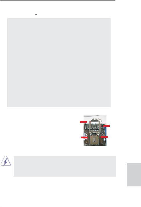
2.1CPU Installation
For the installation of Intel 1155-Pin CPU, |
|
|
|
|
|
|
|
|
|
|
|
|
please follow the steps below. |
|
|
Load Plate |
|
|
|
|
|
|
|
|
|
|
|
|
|
|
||||||||
|
|
|
|
|
|
|
|
|
|
|
||
|
|
|
|
|
|
|
|
|
|
|
|
|
|
|
|
|
|
|
|
|
|
|
Load Lever |
|
|
|
|
|
|
|
|
|
|
|
|
|
|
|
|
|
|
|
|
|
|
|
|
Socket Body |
|
|
|
|
|
|
Contact Array |
|
|
|||||||
|
1155-Pin Socket Overview |
|||||||||||
Before you insert the 1155-Pin CPU into the socket, please check if the CPU surface is unclean or if there is any bent pin on the socket. Do not force to insert the CPU into the socket if above situation is found. Otherwise, the CPU will be seriously damaged.
English
13
ASRock Z68 Extreme3 Gen3 Motherboard
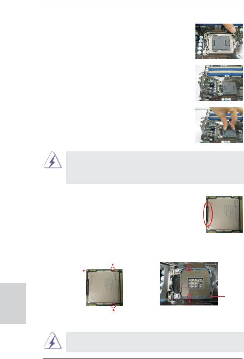
Step 1. Open the socket:
Step 1-1. Disengaging the lever by depressing down and out on the hook to clear retention tab.
Step 1-2. Rotate the load lever to fully open position at approximately 135 degrees.
Step 1-3. Rotate the load plate to fully open position at approximately 100 degrees.
Step 2. Remove PnP Cap (Pick and Place Cap).
English
1.It is recommended to use the cap tab to handle and avoid kicking off the PnP cap.
2.This cap must be placed if returning the motherboard for after service.
Step 3. Insert the 1155-Pin CPU: |
|
|
||||
Step 3-1. |
Hold the CPU by the edges where |
|
lineblack |
|||
|
|
|
are marked with black lines. |
|
||
|
|
|
|
|
||
Step 3-2. |
Orient the CPU with IHS (Integrated |
|
|
|||
|
|
|
Heat Sink) up. Locate Pin1 and the |
|
|
|
|
|
|
two orientation key notches. |
|
|
|
|
orientation key notch |
alignment key |
||||
Pin1 |
|
|
|
|
|
|
|
|
|
|
|
|
|
|
|
|
|
|
|
|
|
|
|
|
|
||
Pin1
|
|
alignment key |
|
|
1155-Pin Socket |
orientation key notch |
||
1155-Pin CPU |
|
|
For proper inserting, please ensure to match the two orientation key notches of the CPU with the two alignment keys of the socket.
14
ASRock Z68 Extreme3 Gen3 Motherboard
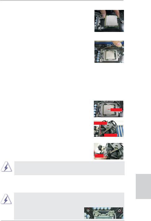
Step 3-3. Carefully place the CPU into the socket by using a purely vertical motion.
Step 3-4. Verify that the CPU is within the socket and properly mated to the orient keys.
Step 4. Close the socket:
Step 4-1. Rotate the load plate onto the IHS. Step 4-2. While pressing down lightly on load
plate, engage the load lever.
Step 4-3. Secure load lever with load plate tab under retention tab of load lever.
2.2Installation of CPU Fan and Heatsink
For proper installation, please kindly refer to the instruction manuals of your CPU fan and heatsink.
Below is an example to illustrate the installation of the heatsink for 1155-Pin CPU. Step 1. Apply thermal interface material onto center of
IHS on the socket surface.
Apply Thermal
Interface Material
Step 2. Place the heatsink onto the socket. Ensure fan cables are oriented on side closest to the CPU fan connector on the motherboard (CPU_ FAN1, see page 2, No. 4).
Step 3. Align fasteners with the motherboard throughholes.
Step 4. Rotate the fastener clockwise, then press down on fastener caps with thumb to install and lock. Repeat with remaining fasteners.
Fan cables on side closest to MB header
Fastener slots pointing straight out
Press Down
(4 Places)
If you press down the fasteners without rotating them clockwise, the heatsink cannot be secured on the motherboard.
Step 5. Connect fan header with the CPU fan connector on the motherboard. Step 6. Secure excess cable with tie-wrap to ensure cable does not interfere with
fan operation or contact other components.
Please be noticed that this motherboard supports Combo Cooler Option (C.C.O.), which provides the flexible option to adopt three different CPU cooler types, Socket LGA 775, LGA 1155 and LGA 1156. The white throughholes are for Socket LGA
1155/1156 CPU fan.
15
English
ASRock Z68 Extreme3 Gen3 Motherboard

2.3 Installation of Memory Modules (DIMM)
This motherboard provides four 240-pin DDR3 (Double Data Rate 3) DIMM slots, and supports Dual Channel Memory Technology. For dual channel configuration, you always need to install identical (the same brand, speed, size and chip-type) DDR3 DIMM pair in the slots: You have to install identical DDR3 DIMM pair in Dual Channel A (DDR3_A1 and DDR3_B1; Black slots; see p.2 No.5) or identical DDR3 DIMM pair in Dual Channel B (DDR3_A2 and DDR3_ B2; Black slots; see p.2 No.6), so that Dual Channel Memory Technology can be activated. This motherboard also allows you to install four DDR3 DIMMs for dual channel configuration, and please install identical DDR3 DIMMs in all four slots. You may refer to the Dual Channel Memory Configuration Table below.
English
16
Dual Channel Memory Configurations
|
DDR3_A1 |
DDR3_A2 |
DDR3_B1 |
DDR3_B2 |
|
(Black Slot) |
(Black Slot) |
(Black Slot) |
(Black Slot) |
(1) |
Populated |
- |
Populated |
- |
(2) |
- |
Populated |
- |
Populated |
(3)* |
Populated |
Populated |
Populated |
Populated |
|
|
|
|
|
*For the configuration (3), please install identical DDR3 DIMMs in all four slots.
1.If you want to install two memory modules, for optimal compatibility and reliability, it is recommended to install them in the slots: DDR3_ A1 and DDR3_B1, or DDR3_A2 and DDR3_B2.
2.If only one memory module or three memory modules are installed in the DDR3 DIMM slots on this motherboard, it is unable to activate the Dual Channel Memory Technology.
3.If a pair of memory modules is NOT installed in the same Dual Channel, for example, installing a pair of memory modules in DDR3_A1 and DDR3_A2, it is unable to activate the Dual Channel Memory Technology .
4.It is not allowed to install a DDR or DDR2 memory module into DDR3 slot; otherwise, this motherboard and DIMM may be damaged.
5.Some DDR3 1GB double-sided DIMMs with 16 chips may not work on this motherboard. It is not recommended to install them on this motherboard.
ASRock Z68 Extreme3 Gen3 Motherboard
Installing a DIMM
Please make sure to disconnect power supply before adding or removing DIMMs or the system components.
Step 1. Unlock a DIMM slot by pressing the retaining clips outward.
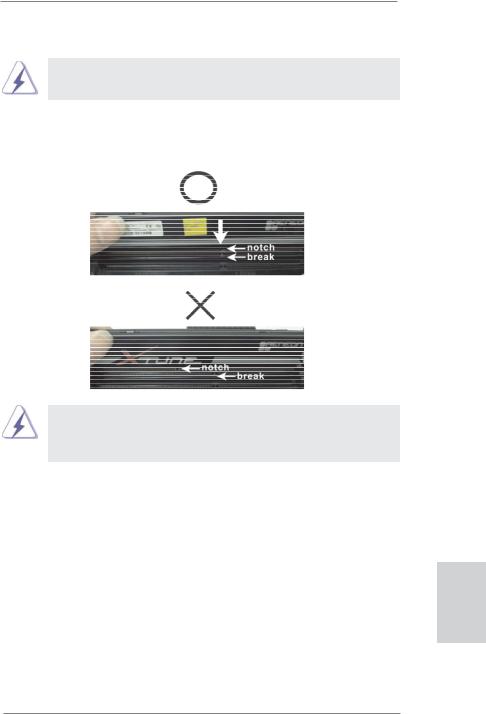
Step 2. Align a DIMM on the slot such that the notch on the DIMM matches the break on the slot.
The DIMM only fits in one correct orientation. It will cause permanent damage to the motherboard and the DIMM if you force the DIMM into the slot at incorrect orientation.
Step 3. Firmly insert the DIMM into the slot until the retaining clips at both ends fully snap back in place and the DIMM is properly seated.
English
17
ASRock Z68 Extreme3 Gen3 Motherboard

English
2.4 Expansion Slots (PCI and PCI Express Slots)
There are 2 PCI slots and 4 PCI Express slots on this motherboard.
PCI slots: PCI slots are used to install expansion cards that have the 32-bit PCI interface.
PCIE slots:
PCIE1/PCIE3 (PCIE 2.0 x1 slot) is used for PCI Express cards with x1 lane width cards, such as Gigabit LAN card, SATA2 card, etc.
PCIE2 (PCIE 3.0 x16 slot) is used for PCI Express x16 lane width graphics cards, or used to install PCI Express graphics cards to support CrossFireXTM or SLITM function.
PCIE4 (PCIE 3.0 x16 slot) is used for PCI Express x8 lane width graphics cards, or used to install PCI Express graphics cards to support CrossFireXTM or SLITM function.
1.In single VGA card mode, it is recommended to install a PCI Express x16 graphics card on PCIE2 slot.
2.In CrossFireXTM mode or SLITM mode, please install PCI Express x16 graphics cards on PCIE2 and PCIE4 slots. Therefore, both these two slots will work at x8 bandwidth.
3.Please connect a chassis fan to motherboard chassis fan connector (CHA_FAN1, CHA_FAN2 or CHA_FAN3) when using multiple graphics cards for better thermal environment.
4.To run the PCI Express in Gen 3 speed, please must install the Ivy Bridge CPU which supports PCI Express Gen3. If you install the Sandy Bridge CPU, the PCI Express will run only at PCI Express Gen 2 speed.
Installing an expansion card
Step 1. Before installing the expansion card, please make sure that the power supply is switched off or the power cord is unplugged. Please read the documentation of the expansion card and make necessary hardware settings for the card before you start the installation.
Step 2. Remove the system unit cover (if your motherboard is already installed in a chassis).
Step 3. Remove the bracket facing the slot that you intend to use. Keep the screws for later use.
Step 4. Align the card connector with the slot and press firmly until the card is completely seated on the slot.
Step 5. Fasten the card to the chassis with screws. Step 6. Replace the system cover.
18
ASRock Z68 Extreme3 Gen3 Motherboard
2.5 SLITM and Quad SLITM Operation Guide
This motherboard supports NVIDIA® SLITM and Quad SLITM (Scalable Link Interface) technology that allows you to install up to three identical PCI Express x16 graphics cards. Currently, NVIDIA® SLITM technology supports Windows® XP / XP 64-bit / VistaTM / VistaTM 64-bit / 7 / 7 64-bit OS. NVIDIA® Quad SLITM technology support Windows® VistaTM / VistaTM 64-bit / 7 / 7 64-bit OS only. Please follow the installation procedures in this section.
Requirements
1.For SLITM technology, you should have two identical SLITM-ready graphics cards that are NVIDIA® certified. For Quad SLITM technology, you should have two identical Quad SLITM-ready graphics cards that are NVIDIA® certified.
2.Make sure that your graphics card driver supports NVIDIA® SLITM technology (driver version 270.61 and later). Download the driver from NVIDIA website (www.nvidia.com).
3.Make sure that your power supply unit (PSU) can provide at least the minimum power required by your system. It is recommended to use NVIDIA® certified PSU. Please refer to NVIDIA® website for details.
2.5.1Graphics Card Setup
2.5.1.1 Installing Two SLITM-Ready Graphics Cards
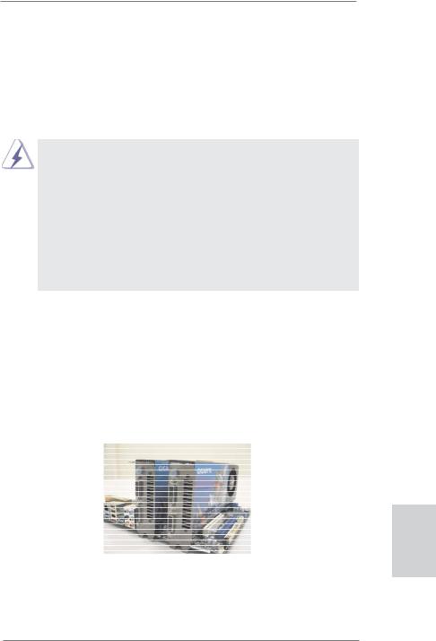
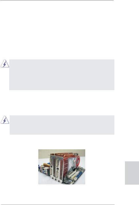
Step 1. Install the identical SLITM-ready graphics cards that are NVIDIA® certified because different types of graphics cards will not work together properly. (Even the GPU chips version shall be the same.) Insert one graphics card into PCIE2 slot and the other graphics card to PCIE4 slot. Make sure that the cards are properly seated on the slots.
English
Step2. If required, connect the auxiliary power source to the PCI Express graphics cards.
19
ASRock Z68 Extreme3 Gen3 Motherboard
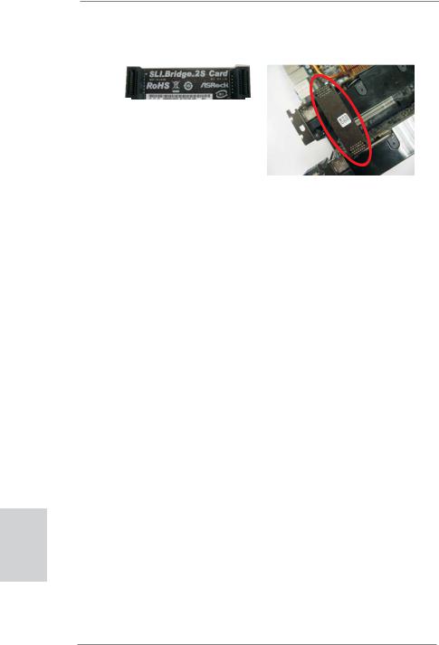
Step3. Align and insert ASRock SLI_Bridge_2S Card to the goldfingers on each graphics card. Make sure ASRock SLI_Bridge_2S Card is firmly in place.
ASRock SLI_Bridge_2S Card
Step4. Connect a VGA cable or a DVI cable to the monitor connector or the DVI connector of the graphics card that is inserted to PCIE2 slot.
English
20
ASRock Z68 Extreme3 Gen3 Motherboard
2.5.2 Driver Installation and Setup
Install the graphics card drivers to your system. After that, you can enable the MultiGraphics Processing Unit (GPU) feature in the NVIDIA® nView system tray utility. Please follow the below procedures to enable the multi-GPU feature.
For Windows® XP / XP 64-bit OS: (For SLITM mode only)
A.Double-click NVIDIA Settings icon on your Windows® taskbar.
B.From the pop-up menu, select Set SLI and PhysX configuration. In
Set PhysX GPU acceleration item, please select Enabled. In Select an SLI configuration item, please select Enable SLI. And click Apply.
C.Reboot your system.
D.You can freely enjoy the benefit of SLITM feature.
English
21
ASRock Z68 Extreme3 Gen3 Motherboard
English
22
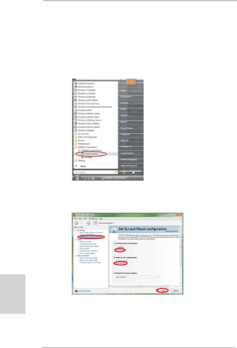
For Windows® VistaTM / VistaTM 64-bit / 7 / 7 64-bit OS: (For SLITM and Quad SLITM mode)
A.Click the Start icon on your Windows taskbar.
B.From the pop-up menu, select All Programs, and then click NVIDIA Corporation.
C.Select NVIDIA Control Panel tab.
D.Select Control Panel tab.
E.From the pop-up menu, select Set SLI and PhysX configuration. In
Set PhysX GPU acceleration item, please select Enabled. In Select an SLI configuration item, please select Enable SLI. And click Apply.
F.Reboot your system.
G.You can freely enjoy the benefit of SLITM or Quad SLITM feature.
*SLITM appearing here is a registered trademark of NVIDIA® Technologies Inc., and is used only for identification or explanation and to the owners’ benefit, without intent to infringe.
ASRock Z68 Extreme3 Gen3 Motherboard
2.6CrossFireXTM and Quad CrossFireXTM Operation Guide
This motherboard supports CrossFireXTM and Quad CrossFireXTM feature. CrossFireXTM technology offers the most advantageous means available of combining multiple high performance Graphics Processing Units (GPU) in a single PC. Combining a range of different operating modes with intelligent software design and an innovative interconnect mechanism, CrossFireXTM enables the highest possible level of performance and image quality in any 3D application. Currently CrossFireXTM feature is supported with Windows® XP with Service Pack 2 / VistaTM / 7 OS. Quad CrossFireXTM feature are supported with Windows® VistaTM / 7 OS only. Please check AMD website for ATITM CrossFireXTM driver updates.
1.If a customer incorrectly configures their system they will not see the performance benefits of CrossFireXTM. All three CrossFireXTM components, a CrossFireXTM Ready graphics card, a CrossFireXTM Ready motherboard and a CrossFireXTM Edition co-processor graphics card, must be installed correctly to benefit from the CrossFireXTM multi-GPU platform.
2.If you pair a 12-pipe CrossFireXTM Edition card with a 16-pipe card, both cards will operate as 12-pipe cards while in CrossFireXTM mode.
2.6.1Graphics Card Setup
2.6.1.1 Installing Two CrossFireXTM-Ready Graphics Cards
Different CrossFireXTM cards may require different methods to enable CrossFireXTM feature. In below procedures, we use Radeon HD 3870 as the example graphics card. For other CrossFireXTM cards that AMD has released or will release in the future, please refer to AMD graphics card manuals for detailed installation guide.
Step 1. Insert one Radeon graphics card into PCIE2 slot and the other Radeon graphics card to PCIE4 slot. Make sure that the cards are properly seated on the slots.
English
23
ASRock Z68 Extreme3 Gen3 Motherboard
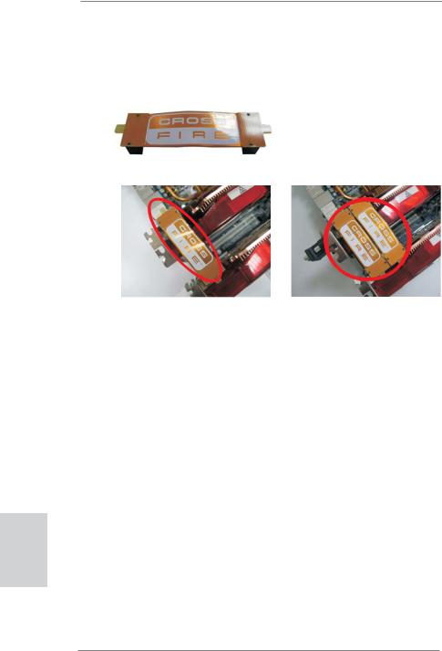
Step 2. Connect two Radeon graphics cards by installing CrossFire Bridge on CrossFire Bridge Interconnects on the top of Radeon graphics cards. (CrossFire Bridge is provided with the graphics card you purchase, not bundled with this motherboard. Please refer to your graphics card vendor for details.)
CrossFire Bridge
or
Step 3. Connect the DVI monitor cable to the DVI connector on the Radeon graphics card on PCIE2 slot. (You may use the DVI to D-Sub adapter to convert the DVI connector to D-Sub interface, and then connect the D-Sub monitor cable to the DVI to D-Sub adapter.)
English
24
ASRock Z68 Extreme3 Gen3 Motherboard
2.6.2 Driver Installation and Setup
Step 1. Power on your computer and boot into OS.
Step 2. Remove the AMD driver if you have any VGA driver installed in your system.
The Catalyst Uninstaller is an optional download. We recommend using this utility to uninstall any previously installed Catalyst drivers prior to installation. Please check AMD website for ATITM driver updates.
Step 3. Install the required drivers to your system.
For Windows® XP OS:
A.AMD recommends Windows® XP Service Pack 2 or higher to be installed (If you have Windows® XP Service Pack 2 or higher installed in your system, there is no need to download it again): http://www.microsoft.com/windowsxp/sp2/default.mspx
B.You must have Microsoft .NET Framework installed prior to downloading and installing the CATALYST Control Center. Please check Microsoft website for details.
For Windows® 7 / VistaTM OS:
Install the CATALYST Control Center. Please check AMD website for details.
Step 4. Restart your computer.
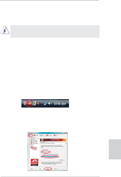
Step 5. Install the VGA card drivers to your system, and restart your computer. Then you will find “ATI Catalyst Control Center” on your Windows® taskbar.
ATI Catalyst Control Center
Step 6. Double-click “ATI Catalyst Control Center”. Click “View”, select “CrossFireXTM”, and then check the item “Enable CrossFireXTM”. Select “2 GPUs” and click “Apply” (if you install two Radeon graphics cards). Select “3 GPUs” and click “OK” (if you install three Radeon graphics cards).
English
25
ASRock Z68 Extreme3 Gen3 Motherboard

Although you have selected the option “Enable CrossFireTM”, the CrossFireXTM function may not work actually. Your computer will automatically reboot. After restarting your computer, please confirm whether the option “Enable CrossFireTM” in “ATI Catalyst Control Center” is selected or not; if not, please select it again, and then you are able to enjoy the benefit of CrossFireXTM feature.
Step 7. You can freely enjoy the benefit of CrossFireXTM or Quad CrossFireXTM feature.
*CrossFireXTM appearing here is a registered trademark of AMD Technologies Inc., and is used only for identification or explanation and to the owners’ benefit, without intent to infringe.
*For further information of AMD CrossFireXTM technology, please check AMD website for updates and details.
English
26
ASRock Z68 Extreme3 Gen3 Motherboard
2.7 Dual Monitor and Surround Display Features
Dual Monitor Feature
This motherboard supports dual monitor feature. With the internal VGA output support (DVI-D, D-Sub and HDMI), you can easily enjoy the benefits of dual monitor feature without installing any add-on VGA card to this motherboard. This motherboard also provides independent display controllers for DVI-D, D-Sub and HDMI to support dual VGA output so that DVI-D, D-sub and HDMI can drive same or different display contents.
To enable dual monitor feature, please follow the below steps:
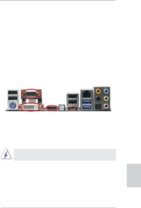
1.Connect DVI-D monitor cable to DVI-D port on the I/O panel, connect D-Sub monitor cable to D-Sub port on the I/O panel, connect HDMI monitor cable to HDMI port on the I/O panel.
D-Sub port
DVI-D port |
HDMI port |
2.If you have installed onboard VGA driver from our support CD to your system already, you can freely enjoy the benefits of dual monitor function after your system boots. If you haven’t installed onboard VGA driver yet, please install onboard VGA driver from our support CD to your system and restart your computer.
D-Sub, DVI-D and HDMI monitors cannot be enabled at the same time.
You can only choose two of them.
English
27
ASRock Z68 Extreme3 Gen3 Motherboard

English
28
Surround Display Feature
This motherboard supports surround display upgrade. With the internal VGA output support (DVI-D, D-Sub and HDMI) and external add-on PCI Express VGA cards, you can easily enjoy the benefits of surround display feature.
Please refer to the following steps to set up a surround display environment:
1.Install the PCI Express VGA cards on PCIE2 and PCIE4 slots. Please refer to page 18 for proper expansion card installation procedures for details.
2.Connect DVI-D monitor cable to DVI-D port on the I/O panel, connect D-Sub monitor cable to D-Sub port on the I/O panel, connect HDMI monitor cable to HDMI port on the I/O panel. Then connect other monitor cables to the
corresponding connectors of the add-on PCI Express VGA cards on PCIE2 and
PCIE4 slots.
3.Boot your system. Press <F2> or <Del> to enter UEFI setup. Enter “Onboard VGA Share Memory” option to adjust the memory capability to [32MB], [64MB], [128MB], [256MB] or [512MB] to enable the function of D-sub. Please make sure that the value you select is less than the total capability of the system memory. If you do not adjust the UEFI setup, the default value of “Onboard VGA Share Memory”, [Auto], will disable D-Sub function when the add-on VGA card is inserted to this motherboard.
4.Install the onboard VGA driver and the add-on PCI Express VGA card driver to your system. If you have installed the drivers already, there is no need to install them again.
5.Set up a multi-monitor display.
For Windows® XP / XP 64-bit OS:
Right click the desktop, choose “Properties”, and select the “Settings” tab so that you can adjust the parameters of the multi-monitor according to the steps below.
A.Click the “Identify” button to display a large number on each monitor.
B.Right-click the display icon in the Display Properties dialog that you wish to be your primary monitor, and then select “Primary”. When you use multiple monitors with your card, one monitor will always be Primary, and all additional monitors will be designated as Secondary.
C.Select the display icon identified by the number 2.
D.Click “Extend my Windows desktop onto this monitor”.
E.Right-click the display icon and select “Attached”, if necessary.
F.Set the “Screen Resolution” and “Color Quality” as appropriate for the second monitor. Click “Apply” or “OK” to apply these new values.
G.Repeat steps C through E for the diaplay icon identified by the number one to six.
ASRock Z68 Extreme3 Gen3 Motherboard

For Windows® 7 / 7 64-bit / VistaTM / VistaTM 64-bit OS:
Right click the desktop, choose “Personalize”, and select the “Display Settings” tab so that you can adjust the parameters of the multi-monitor according to the steps below.
A.Click the number ”2” icon.
B.Click the items “This is my main monitor” and “Extend the desktop onto this monitor”.
C.Click “OK” to save your change.
D.Repeat steps A through C for the display icon identified by the number three to six.
6.Use Surround Display. Click and drag the display icons to positions representing the physical setup of your monitors that you would like to use. The placement of display icons determines how you move items from one monitor to another.
HDCP Function
HDCP function is supported on this motherboard. To use HDCP function with this motherboard, you need to adopt the monitor that supports HDCP function as well. Therefore, you can enjoy the superior display quality with high-definition HDCP encryption contents. Please refer to below instruction for more details about HDCP function.
What is HDCP?
HDCP stands for High-Bandwidth Digital Content Protection, a specification developed by Intel® for protecting digital entertainment content that uses the DVI interface. HDCP is a copy protection scheme to eliminate the possibility of intercepting digital data midstream between the video source,
or transmitter - such as a computer, DVD player or set-top box - and the digital display, or receiver - such as a monitor, television or projector. In other words, HDCP specification is designed to protect the integrity of content as it is being transmitted.
Products compatible with the HDCP scheme such as DVD players, satellite and cable HDTV set-top-boxes, as well as few entertainment PCs requires a secure connection to a compliant display. Due to the increase in manufacturers employing HDCP in their equipment, it is highly recommended that the HDTV or LCD monitor you purchase is compatible.
29
English
ASRock Z68 Extreme3 Gen3 Motherboard
English
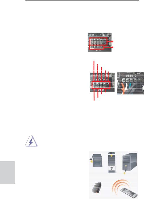
2.8 ASRock Smart Remote Installation Guide
ASRock Smart Remote is only used for ASRock motherboard with CIR header. Please refer to below procedures for the quick installation and usage of ASRock Smart Remote.
Step1. Find the CIR header located next to the USB 2.0 header on ASRock
motherboard. |
USB 2.0 header (9-pin, black) |
|
|
|
CIR header (4-pin, gray) |
Step2. Connect the front USB cable to the USB 2.0 header (as below, pin 1-5) and the CIR header. Please make sure the wire assignments and the pin assignments are matched correctly.
USB_PWR
P-
P+
GND DUMMY
|
GND |
|
IRTX |
|
IRRX |
|
ATX+5VSB |
Step3. |
Install Multi-Angle CIR Receiver to the front USB port. |
Step4. |
Boot up your system. Press <F2> or <Del> to enter BIOS Setup Utility. |
|
Make sure the option "CIR Controller" is setting at [Enabled]. |
|
(Advanced -> Super IO Configuration -> CIR Controller -> [Enabled]) |
|
|
|
If you cannot find this option, please shut down your system and install |
|
Multi-Angle CIR Receiver to the other front USB port then try again. |
|
|
Step5. |
Enter Windows. Execute ASRock |
|
support CD and install CIR Driver. |
|
(It is listed at the bottom of driver |
|
list.) |
3 CIR sensors in different angles
30
ASRock Z68 Extreme3 Gen3 Motherboard
 Loading...