


G41M-VGS3 / G41M-VS3
User Manual
Version 2.0
Published December 2010 Copyright©2010 ASRock INC. All rights reserved.
1
Copyright Notice:
No part of this manual may be reproduced, transcribed, transmitted, or translated in any language, in any form or by any means, except duplication of documentation by the purchaser for backup purpose, without written consent of ASRock Inc.
Products and corporate names appearing in this manual may or may not be registered trademarks or copyrights of their respective companies, and are used only for identification or explanation and to the owners’ benefit, without intent to infringe.
Disclaimer:
Specifications and information contained in this manual are furnished for informational use only and subject to change without notice, and should not be constructed as a commitment by ASRock. ASRock assumes no responsibility for any errors or omissions that may appear in this manual.
With respect to the contents of this manual, ASRock does not provide warranty of any kind, either expressed or implied, including but not limited to the implied warranties or conditions of merchantability or fitness for a particular purpose.
In no event shall ASRock, its directors, officers, employees, or agents be liable for any indirect, special, incidental, or consequential damages (including damages for loss of profits, loss of business, loss of data, interruption of business and the like), even if ASRock has been advised of the possibility of such damages arising from any defect or error in the manual or product.
This device complies with Part 15 of the FCC Rules. Operation is subject to the following two conditions:
(1)this device may not cause harmful interference, and
(2)this device must accept any interference received, including interference that may cause undesired operation.
CALIFORNIA, USA ONLY
The Lithium battery adopted on this motherboard contains Perchlorate, a toxic substance controlled in Perchlorate Best Management Practices (BMP) regulations passed by the California Legislature. When you discard the Lithium battery in California, USA, please follow the related regulations in advance.
“Perchlorate Material-special handling may apply, see www.dtsc.ca.gov/hazardouswaste/perchlorate”
ASRock Website: http://www.asrock.com
2

Contents
1 Introduction ................................................... |
5 |
||
1.1 |
Package Contents .......................................................... |
5 |
|
1.2 |
Specifications ................................................................ |
6 |
|
1.3 |
Motherboard Layout (G41M-VGS3 / G41M-VS3) ......... |
11 |
|
1.4 |
I/O Panel (G41M-VGS3) ................................................ |
12 |
|
1.5 |
I/O Panel (G41M-VS3) ................................................... |
13 |
|
2 Installation...................................................... |
14 |
||
2.1 |
Screw Holes ................................................................. |
14 |
|
2.2 |
Pre-installation Precautions ........................................... |
14 |
|
2.3 |
CPU Installation .............................................................. |
15 |
|
2.4 |
Installation of Heatsink and CPU fan ............................. |
17 |
|
2.5 |
Installation of Memory Modules (DIMM) ......................... |
18 |
|
2.6 |
Expansion Slots (PCI and PCI Express Slots) ..................... |
19 |
|
2.7 |
Jumpers Setup .............................................................. |
20 |
|
2.8 |
Onboard Headers and Connectors .............................. |
21 |
|
2.9 |
SATAII Hard Disk Setup Guide ....................................... |
24 |
|
2.10 Serial ATA (SATA) / Serial ATAII (SATAII) Hard Disks |
|
||
|
Installation ...................................................................... |
25 |
|
2.11 |
Driver Installation Guide .............................................. |
25 |
|
2.12 |
Untied Overclocking Technology .................................. |
25 |
|
3 BIOS SETUP UTILITY ........................................... |
26 |
||
3.1 |
Introduction .................................................................... |
26 |
|
|
3.1.1 BIOS Menu Bar .................................................... |
26 |
|
|
3.1.2 Navigation Keys ................................................... |
27 |
|
3.2 |
Main Screen ................................................................... |
27 |
|
3.3 |
OC Tweaker Screen ...................................................... |
29 |
|
3.4 |
Advanced Screen ......................................................... |
32 |
|
|
3.4.1 CPU Configuration ................................................ |
33 |
|
|
3.4.2 |
Chipset Configuration .......................................... |
35 |
|
3.4.3 ACPI Configuration ............................................... |
41 |
|
|
3.4.4 |
Storage Configuration ......................................... |
42 |
|
3.4.5 PCIPnP Configuration ........................................... |
44 |
|
|
3.4.6 |
Super IO Configuration ........................................ |
45 |
|
3.4.7 |
USB Configuration ............................................... |
46 |
3.5 |
Hardware Health Event Monitoring Screen .................. |
47 |
|
3.6 |
Boot Screen ................................................................... |
48 |
|
|
3.6.1 Boot Settings Configuration .................................. |
48 |
|
3.7 |
Security Screen ............................................................ |
49 |
|
3.8 |
Exit Screen .................................................................... |
50 |
|
3

4 Software Support ........................................... |
51 |
4.1 |
Install Operating System ............................................... |
51 |
|
4.2 |
Support CD Information ................................................. |
51 |
|
|
4.2.1 Running Support CD ............................................ |
51 |
|
|
4.2.2 Drivers Menu ........................................................ |
51 |
|
|
4.2.3 |
Utilities Menu ........................................................ |
51 |
|
4.2.4 |
Contact Information .............................................. |
51 |
4
Chapter 1 Introduction
Thank you for purchasing ASRock G41M-VGS3 / G41M-VS3 motherboard, a reliable motherboard produced under ASRock’s consistently stringent quality control. It delivers excellent performance with robust design conforming to ASRock’s commitment to quality and endurance.
In this manual, chapter 1 and 2 contain introduction of the motherboard and step-by-step guide to the hardware installation. Chapter 3 and 4 contain the configuration guide to BIOS setup and information of the Support CD.
Because the motherboard specifications and the BIOS software might be updated, the content of this manual will be subject to change without notice. In case any modifications of this manual occur, the updated version will be available on ASRock website without further notice. You may find the latest VGA cards and CPU support lists on ASRock website as well. ASRock website http://www.asrock.com
If you require technical support related to this motherboard, please visit our website for specific information about the model you are using. www.asrock.com/support/index.asp
1.1 Package Contents
ASRock G41M-VGS3 / G41M-VS3 Motherboard
(Micro ATX Form Factor: 8.9-in x 6.7-in, 22.6 cm x 17.0 cm) ASRock G41M-VGS3 / G41M-VS3 Quick Installation Guide ASRock G41M-VGS3 / G41M-VS3 Support CD
Two Serial ATA (SATA) Data Cables (Optional) One I/O Panel Shield
5

1.2 Specifications
Platform |
- Micro ATX Form Factor: 8.9-in x 6.7-in, 22.6 cm x 17.0 cm |
CPU |
- LGA 775 for Intel® CoreTM 2 Extreme / CoreTM 2 Quad / CoreTM |
|
2 Duo / Pentium® Dual Core / Celeron® Dual Core / Celeron®, |
|
supporting Penryn Quad Core Yorkfield and Dual Core |
|
Wolfdale processors |
|
- Supports FSB1333/1066/800/533 MHz |
|
- Supports Hyper-Threading Technology (see CAUTION 1) |
|
- Supports Untied Overclocking Technology (see CAUTION 2) |
|
- Supports EM64T CPU |
Chipset |
- Northbridge: Intel® G41 |
|
- Southbridge: Intel® ICH7 |
Memory |
- Dual Channel DDR3 Memory Technology (see CAUTION 3) |
|
- 2 x DDR3 DIMM slots |
|
- Supports DDR3 1333(OC)/1066/800 non-ECC, un-buffered |
|
memory (see CAUTION 4) |
|
- Max. capacity of system memory: 8GB (see CAUTION 5) |
Expansion Slot |
- 1 x PCI Express x16 slot |
|
- 1 x PCI slot |
Graphics |
- Intel® Graphics Media Accelerator X4500 |
|
- Pixel Shader 4.0, DirectX 10 |
|
- Max. shared memory 1759MB (see CAUTION 6) |
|
- Supports D-Sub with max. resolution up to 2048x1536 @ |
|
75Hz |
Audio |
- 5.1 CH HD Audio (VIA® VT1705 Audio Codec) |
LAN |
- G41M-VGS3 |
|
Atheros® PCIE x1 Gigabit LAN AR8151, |
|
speed 10/100/1000 Mb/s |
|
- G41M-VS3 |
|
Atheros® PCIE x1 LAN AR8152, speed 10/100 Mb/s |
|
- Supports Wake-On-LAN |
Rear Panel I/O |
I/O Panel |
|
- 1 x PS/2 Mouse Port |
|
- 1 x PS/2 Keyboard Port |
|
- 1 x VGA Port |
|
- 4 x Ready-to-Use USB 2.0 Ports |
|
- 1 x RJ-45 LAN Port with LED (ACT/LINK LED and SPEED LED) |
|
- HD Audio Jack: Line in / Front Speaker / Microphone |
|
|
6

Connector |
- 4 x SATAII 3.0 Gb/s connectors (No Support for RAID and |
|
“Hot Plug” functions) (see CAUTION 7) |
|
- 1 x ATA100 IDE connector (supports 2 x IDE devices) |
|
- 1 x Print port header |
|
- 1 x COM port header |
|
- CPU/Chassis FAN connector |
|
- 24 pin ATX power connector |
|
- 4 pin 12V power connector |
|
- Front panel audio connector |
|
- 2 x USB 2.0 headers (support 4 USB 2.0 ports) |
|
(see CAUTION 8) |
BIOS Feature |
- 8Mb AMI BIOS |
|
- AMI Legal BIOS |
|
- Supports “Plug and Play” |
|
- ACPI 1.1 Compliance Wake Up Events |
|
- AMBIOS 2.3.1 Support |
|
- VCCM, NB, VTT, GTLRef Voltage Multi-adjustment |
Support CD |
- Drivers, Utilities, AntiVirus Software (Trial Version), |
|
ASRock Software Suite (CyberLink DVD Suite - OEM and |
|
Trial; Creative Sound Blaster X-Fi MB - Trial) |
Unique Feature |
- ASRock OC Tuner (see CAUTION 9) |
|
- Intelligent Energy Saver (see CAUTION 10) |
|
- Instant Boot |
|
- ASRock Instant Flash (see CAUTION 11) |
|
- ASRock OC DNA (see CAUTION 12) |
|
- ASRock AIWI (see CAUTION 13) |
|
- ASRock APP Charger (see CAUTION 14) |
|
- SmartView (see CAUTION 15) |
|
- ASRock XFast USB (see CAUTION 16) |
|
- Hybrid Booster: |
|
- CPU Frequency Stepless Control (see CAUTION 17) |
|
- ASRock U-COP (see CAUTION 18) |
|
- Boot Failure Guard (B.F.G.) |
Hardware |
- CPU Temperature Sensing |
Monitor |
- Chassis Temperature Sensing |
|
- CPU Fan Tachometer |
|
- Chassis Fan Tachometer |
|
- CPU Quiet Fan |
|
- Voltage Monitoring: +12V, +5V, +3.3V, Vcore |
OS |
- Microsoft® Windows® 7 / 7 64-bit / VistaTM / VistaTM 64-bit / XP |
|
/ XP 64-bit compliant |
|
|
7

Certifications |
- FCC, CE, WHQL |
-ErP/EuP Ready (ErP/EuP ready power supply is required) (see CAUTION 19)
*For detailed product information, please visit our website: http://www.asrock.com
WARNING
Please realize that there is a certain risk involved with overclocking, including adjusting the setting in the BIOS, applying Untied Overclocking Technology, or using the thirdparty overclocking tools. Overclocking may affect your system stability, or even cause damage to the components and devices of your system. It should be done at your own risk and expense. We are not responsible for possible damage caused by overclocking.
CAUTION!
1. About the setting of “Hyper Threading Technology”, please check page 34. 2. This motherboard supports Untied Overclocking Technology. Please read
|
“Untied Overclocking Technology” on page 25 for details. |
|||
3. |
This motherboard supports Dual Channel Memory Technology. Before you |
|||
|
|
implement Dual Channel Memory Technology, make sure to read the |
||
|
|
installation guide of memory modules on page 18 for proper installation. |
||
4. |
|
Please check the table below for the CPU FSB frequency and its |
||
|
|
corresponding memory support frequency. |
||
|
|
CPU FSB Frequency |
Memory Support Frequency |
|
|
|
1333 |
DDR3 800, DDR3 1066, DDR3 1333 |
|
|
|
1066 |
DDR3 800, DDR3 1066 |
|
|
|
800 |
DDR3 800 |
|
|
|
533 |
DDR3 800 |
|
|
|
* DDR3 1333 memory modules will operate in overclocking mode. |
||
|
|
* When you use a FSB533-CPU on this motherboard, it will run at |
||
|
|
DDR3 533 if you adopt a DDR3 800 memory module. |
||
|
|
* If you adopt FSB1333-CPU and DDR3 1333 memory module on this |
||
|
|
motherboard, you need to adjust the jumper. Please refer to page 21 for |
||
|
|
proper jumper settings. |
|
|
5. |
|
Due to the operating system limitation, the actual memory size may be |
||
|
|
less than 4GB for the reservation for system usage under Windows® 7 / |
||
|
VistaTM / XP. For Windows® OS with 64-bit CPU, there is no such limitation. |
|||
6. |
The maximum shared memory size is defined by the chipset vendor and |
|||
|
is subject to change. Please check Intel® website for the latest information. |
|||
7. |
Before installing SATAII hard disk to SATAII connector, please read the “SATAII |
|||
|
Hard Disk Setup Guide” on page 24 to adjust your SATAII hard disk drive to |
|||
|
SATAII mode. You can also connect SATA hard disk to SATAII connector |
|||
|
directly. |
|
|
|
8. |
Power Management for USB 2.0 works fine under Microsoft® Windows® 7 |
|||
|
|
64-bit / 7 / VistaTM 64-bit / VistaTM / XP 64-bit / XP SP1 or SP2. |
||
8

9.It is a user-friendly ASRock overclocking tool which allows you to surveil your system by hardware monitor function and overclock your hardware devices to get the best system performance under Windows® environment. Please visit our website for the operation procedures of ASRock OC Tuner. ASRock website: http://www.asrock.com
10.Featuring an advanced proprietary hardware and software design, Intelligent Energy Saver is a revolutionary technology that delivers unparalleled power savings. In other words, it is able to provide exceptional power saving and improve power efficiency without sacrificing computing performance. Please visit our website for the operation procedures of Intelligent Energy Saver.
ASRock website: http://www.asrock.com
11.ASRock Instant Flash is a BIOS flash utility embedded in Flash ROM. This convenient BIOS update tool allows you to update system BIOS without entering operating systems first like MS-DOS or Windows®. With this utility, you can press <F6> key during the POST or press <F2> key to BIOS setup menu to access ASRock Instant Flash. Just launch this tool and save the new BIOS file to your USB flash drive, floppy disk or hard drive, then you can update your BIOS only in a few clicks without preparing an additional floppy diskette or other complicated flash utility. Please be noted that the USB flash drive or hard drive must use FAT32/16/12 file system.
12.The software name itself – OC DNA literally tells you what it is capable of. OC DNA, an exclusive utility developed by ASRock, provides a convenient way for the user to record the OC settings and share with others. It helps you to save your overclocking record under the operating system and simplifies the complicated recording process of overclocking settings. With OC DNA, you can save your OC settings as a profile and share with your friends! Your friends then can load the OC profile to their own system to get the same OC settings as yours! Please be noticed that the OC profile can only be shared and worked on the same motherboard.
13.To experience intuitive motion controlled games is no longer only available at Wii. ASRock AIWI utility introduces a new way of PC gaming operation. ASRock AIWI is the world's first utility to turn your iPhone/iPod touch as a game joystick to control your PC games. All you have to do is just to install the ASRock AIWI utility either from ASRock official website or ASRock software support CD to your motherboard, and also download the free AIWI Lite from App store to your iPhone/iPod touch. Connecting your PC and apple devices via Bluetooth or WiFi networks, then you can start experiencing the exciting motion controlled games. Also, please do not forget to pay attention to ASRock official website regularly, we will continuously provide you the most up-do-date supported games! ASRock website: http://www.asrock.com/Feature/Aiwi/index.asp
9

14.If you desire a faster, less restricted way of charging your Apple devices, such as iPhone/iPod/iPad Touch, ASRock has prepared a wonderful solution for you - ASRock APP Charger. Simply installing the APP Charger driver, it makes your iPhone charged much quickly from your computer and up to 40% faster than before. ASRock APP Charger allows you to quickly charge many Apple devices simultaneously and even supports continuous charging when your PC enters into Standby mode (S1), Suspend to RAM (S3), hibernation mode (S4) or power off (S5). With APP Charger driver installed, you can easily enjoy the marvelous charging experience than ever.
ASRock website: http://www.asrock.com/Feature/AppCharger/index.asp
15.SmartView, a new function of internet browser, is the smart start page for IE that combines your most visited web sites, your history, your Facebook friends and your real-time newsfeed into an enhanced view for a more personal Internet experience. ASRock motherboards are exclusively equipped with the SmartView utility that helps you keep in touch with friends on-the-go. To use SmartView feature, please make sure your OS version is Windows® 7 / 7 64 bit / VistaTM / VistaTM 64 bit, and your browser version is IE8.
ASRock website: http://www.asrock.com/Feature/SmartView/index.asp
16.ASRock XFast USB can boost USB storage device performance. The performance may depend on the property of the device.
17.Although this motherboard offers stepless control, it is not recommended to perform over-clocking. Frequencies other than the recommended CPU bus frequencies may cause the instability of the system or damage the CPU.
18.While CPU overheat is detected, the system will automatically shutdown. Before you resume the system, please check if the CPU fan on the motherboard functions properly and unplug the power cord, then plug it back again. To improve heat dissipation, remember to spray thermal grease between the CPU and the heatsink when you install the PC system.
19.EuP, stands for Energy Using Product, was a provision regulated by European Union to define the power consumption for the completed system. According to EuP, the total AC power of the completed system shall be under 1.00W in off mode condition. To meet EuP standard, an EuP ready motherboard and an EuP ready power supply are required. According to Intel’s suggestion, the EuP ready power supply must meet the standard of 5v standby power efficiency is higher than 50% under 100 mA current consumption. For EuP ready power supply selection, we recommend you checking with the power supply manufacturer for more details.
1 0

1.3 Motherboard Layout (G41M-VGS3 / G41M-VS3) |
|||||||||||||
|
|
|
1 |
2 |
|
3 |
|
4 |
|
|
|
5 |
|
|
|
|
|
|
|
17.0cm (6.7 in) |
|
|
|
|
|
||
|
Keyboard PS2 Mouse PS2 |
1 |
|
|
|
|
|
|
|
|
|
|
|
|
|
PS2_USB_PWR1 |
|
|
CPU_FAN1 |
|
|
|
|
|
|
||
|
|
|
|
|
|
|
|
|
|
|
|||
|
|
|
|
ATX12V2 |
|
|
|
|
|
|
|
||
28 |
VGA1 |
|
|
|
|
|
|
FSB1333 |
ErP/EuPReady |
DesignedinTaipei DDR31333 DualChannel |
module) |
module) |
|
|
|
|
|
|
|
pin |
pin |
|
|||||
|
|
|
|
|
|
|
|
||||||
|
|
|
|
|
|
|
FSB800 |
FSB800 |
22.6cm(8.9in) |
||||
|
USB 2.0 |
|
|
|
|
|
|
|
|
|
DDR3 A1(64bit,240- |
DDR3 B1(64bit,240- |
|
|
T: USB2 |
|
|
|
|
|
|
|
|
|
|||
|
B: USB3 |
|
|
|
|
|
|
|
|
|
|||
|
LAN |
|
|
|
|
|
|
|
|
||||
|
PHY |
|
|
|
|
|
|
|
|
||||
27 |
|
|
|
|
|
|
|
|
|
|
|||
|
|
|
|
|
|
|
|
|
|
|
|||
|
USB 2.0 |
|
|
|
|
1 |
|
|
|
|
|
|
|
|
Top: |
|
|
|
Intel |
|
|
|
|
|
|||
|
T: USB0 |
|
|
|
|
|
|
|
|
||||
|
RJ-45 |
|
|
|
|
|
|
|
|
||||
|
B: USB1 |
|
|
|
|
|
G41 |
|
|
|
|
|
|
26 |
|
|
|
|
|
|
|
|
|
|
|
||
|
|
|
|
|
|
Chipset |
|
|
|
|
|
||
25 |
Mic Bottom: Line Center: In Out |
|
Super |
|
|
|
|
|
|
|
|||
|
Line Top: In |
|
|
|
|
|
|
|
|
|
|||
|
COM1 |
IO |
|
|
|
|
|
|
|
|
|
||
|
|
|
|
|
|
|
|
|
|
|
|||
|
|
|
|
|
|
FSB1 |
|
|
|
|
|
|
|
24 |
HD_AUDIO1 |
|
1 |
|
|
1 |
|
|
|
|
|
|
|
|
|
EUP_LAN |
|
|
LPT1 |
|
|
|
|
|
|
|
|
23 |
1 |
|
1 |
|
|
|
|
|
|
|
|
|
6 |
|
|
|
|
|
|
|
|
|
|
|
|||
|
|
1 |
|
|
|
|
|
|
|
|
|
||
22 |
|
|
EUP_AUDIO1 |
|
|
|
|
|
|
|
|
|
|
|
|
|
|
|
|
PCIE1 |
|
|
|
|
|
|
|
21 |
|
|
|
|
|
|
|
|
|
|
|
|
|
20 |
|
|
|
|
|
|
|
|
|
|
|
|
|
|
AUDIO |
|
|
|
|
|
|
|
|
|
|
|
|
|
CODEC |
|
|
|
|
|
|
|
Intel |
|
|
|
|
|
|
|
CMOS |
|
|
|
DX10 |
|
|
|
7 |
||
19 |
8Mb |
|
Battery |
|
RoHS |
|
|
ICH7 |
|
|
|||
|
|
|
|
|
|
|
|||||||
BIOS |
|
|
|
|
|
|
|
|
|||||
18 |
|
USB6_7 |
|
|
|
PCI1 |
|
|
|
|
|
|
|
|
|
|
|
|
|
|
|
|
|
|
|
||
17 |
|
|
|
|
|
|
PLED PWRBTN |
|
|
|
|
|
|
|
|
|
|
|
SPEAKER1 |
|
|
|
|
|
|
8 |
|
CHA_FAN1 1 |
|
|
CLRCMOS1 |
1 |
1 |
PANEL 1 |
|
|
IDE1 |
|
|
||
|
|
|
|
|
|
|
|
|
|
||||
|
|
|
|
|
|
|
HDLED RESET |
|
|
|
|
|
|
|
1 |
|
|
|
|
|
|
|
|
|
|
|
|
|
|
USB4_5 |
|
|
|
|
|
|
|
|
|
|
|
|
|
|
|
SATAII_4 |
|
SATAII_3 |
SATAII_2 |
SATAII_1 |
|
|
|
|
|
|
16 |
|
15 14 |
13 |
12 |
11 |
10 |
|
9 |
|
|
|
|
1 |
PS2_USB_PWR1 Jumper |
15 |
USB 2.0 Header (USB4_5, Blue) |
2 |
ATX 12V Connector (ATX12V2) |
16 |
Chassis Fan Connector (CHA_FAN1) |
3 |
CPU Fan Connector (CPU_FAN1) |
17 |
USB 2.0 Header (USB6_7, Blue) |
4 |
ATX Power Connector (ATXPWR1) |
18 |
Clear CMOS Jumper (CLRCMOS1) |
5 |
2 x 240-pin DDR3 DIMM Slots |
19 |
BIOS SPI Chip |
|
(Dual Channel: DDR3_A1, DDR3_B1; Blue) |
20 |
PCI Slot (PCI1) |
6 |
North Bridge Controller |
21 |
PCI Express x16 Slot (PCIE1) |
7 |
South Bridge Controller |
22 |
EUP Audio Jumper (EUP_AUDIO1) |
8 |
System Panel Header (PANEL1, White) |
23 |
EUP LAN Jumper (EUP_LAN1) |
9 |
IDE1 Connector (IDE1, Blue) |
24 |
Front Panel Audio Header |
10 |
Primary SATAII Connector (SATAII_1; Blue) |
|
(HD_AUDIO1, White) |
11 |
Secondary SATAII Connector (SATAII_2; Blue) |
25 |
Serial Port Connector (COM1) |
12 |
Third SATAII Connector (SATAII_3; Blue) |
26 |
Print Port Header (LPT1, White) |
13 |
Fourth SATAII Connector (SATAII_4; Blue) |
27 |
FSB1 Jumper |
14 |
Chassis Speaker Header (SPEAKER 1, White) |
28 |
775-Pin CPU Socket |
1 1
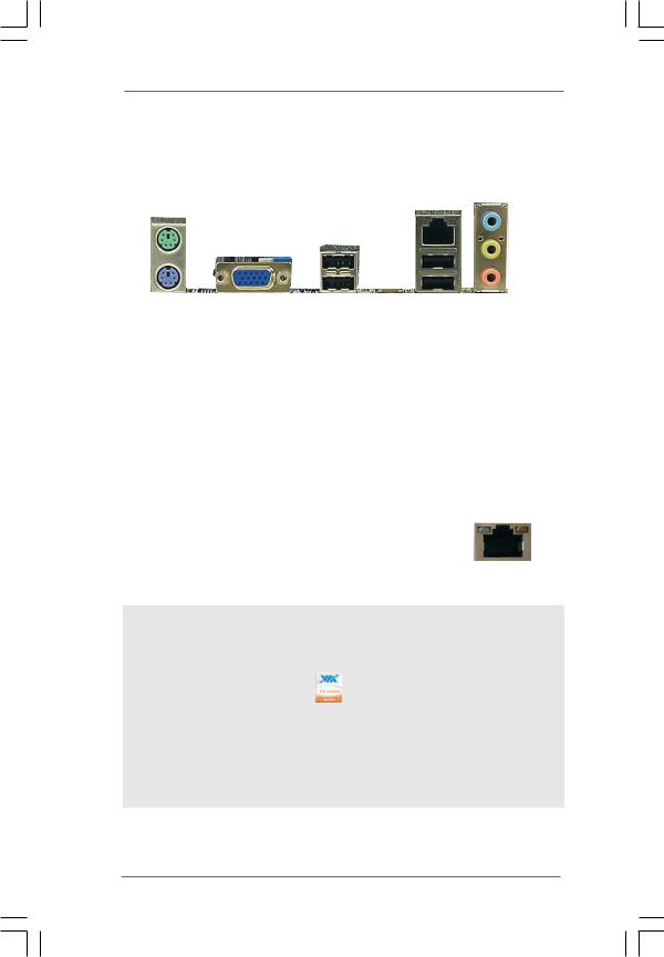
1.4 I/O Panel (G41M-VGS3)
|
1 |
|
|
|
|
|
|
|
|
|
|
|
2 |
|
|
|
|
|
|
|
|
|
|
|
||||
|
|
|
|
|
|
|
|
|
|
|
|
|
|
|
|
|
|
|
|
|
|
|
|
|
3 |
|||
|
|
|
|
|
|
|
|
|
|
|
|
|
|
|
|
|
|
|
|
|
|
|
|
|
||||
|
|
|
|
|
|
|
|
|
|
|
|
|
|
|
|
|
|
|
|
|
|
|
|
|
||||
|
|
|
|
|
|
|
|
|
|
|
|
|
|
|
|
|
|
|
|
|
|
|
|
|
||||
|
|
|
|
|
|
|
|
|
|
|
|
|
|
|
|
|
|
|
|
|
|
|
|
|
4 |
|||
|
|
|
|
|
|
|
|
|
|
|
|
|
|
|
|
|
|
|
|
|
|
|
|
|||||
|
|
|
|
|
|
|
|
|
|
|
|
|
|
|
|
|
|
|
|
|
|
|
|
|
|
|
5 |
|
|
|
|
|
|
|
|
|
|
|
|
|
|
|
|
|
|
|
|
|
|
|
|
|
|
|
|
|
|
|
|
|
|
|
|
|
|
|
|
|
|
|
|
|
|
|
|
|
|
|
||||||||
|
9 |
8 |
|
|
7 |
6 |
|
|
|
|
|
|
|
|||||||||||||||
1 |
PS/2 Mouse Port (Green) |
|
6 |
USB 2.0 Ports (USB01) |
|
|
|
|
|
|
||||||||||||||||||
* 2 |
RJ-45 Port |
|
7 |
USB 2.0 Ports (USB23) |
|
|
|
|
|
|
||||||||||||||||||
3 |
Line In (Light Blue) |
|
8 |
VGA Port |
|
|
|
|
|
|
||||||||||||||||||
4 |
Line Out (Lime) |
|
9 |
PS/2 Keyboard Port (Purple) |
||||||||||||||||||||||||
5 |
Microphone (Pink) |
|
|
|
|
|
|
|
|
|
|
|
|
|
|
|
|
|
|
|
|
|
||||||
|
|
|
|
|
LAN Port LED Indications |
|
|
|
|
|
|
ACT/LINK SPEED |
||||||||||||||||
|
Activity/Link LED |
|
SPEED LED |
|
|
|
|
|
|
|||||||||||||||||||
|
|
|
|
|
|
|
|
|
LED |
|
LED |
|||||||||||||||||
Status |
|
Description |
|
Status |
|
Description |
|
|
|
|
|
|
|
|
||||||||||||||
|
|
|
|
|
|
|
|
|
|
|
|
|
|
|
|
|
|
|||||||||||
|
|
|
|
|
|
|
|
|
|
|
|
|
|
|
|
|||||||||||||
Off |
|
|
|
No Activity |
|
Off |
|
10Mbps connection |
|
|
|
|
|
|
|
|
|
|
|
|||||||||
|
|
|
|
|
|
|
|
|
|
|||||||||||||||||||
Blinking |
|
Data Activity |
|
Orange |
|
100Mbps connection |
|
|
|
|
|
|
|
|
|
|
|
|||||||||||
|
|
|
|
|
|
|
|
|
|
|
|
|
|
|
|
|
|
|
|
|
|
|
|
|
|
|||
|
|
|
|
|
|
|
|
Green |
|
1Gbps connection |
|
|
|
|
|
|
|
|
|
|
||||||||
|
|
|
|
|
|
|
|
|
|
|
|
|
|
|
|
|
|
|
|
|
|
LAN Port |
||||||
|
|
|
|
|
|
|
|
|
|
|
|
|
|
|
|
|
|
|
|
|
|
|||||||
To enable Multi-Streaming function, you need to connect a front panel audio cable to the front panel audio header. After restarting your computer, you will find “VIA HD Audio Deck” tool on your system. Please follow below instructions according to the OS you install.
For Windows® XP / XP 64-bit OS: |
|
Please click “VIA HD Audio Deck” icon |
, and click “Speaker”. Then you are allowed to |
select “2 Channel” or “4 Channel”. Click “Power” to save your change.
For Windows® 7 / 7 64-bit / VistaTM / VistaTM 64-bit OS:
Please click “VIA HD Audio Deck” icon  , and click “Advanced Options” on the left side
on the bottom. In “Advanced Options” screen, select “Independent Headphone”, and click “OK” to save your change.
1 2
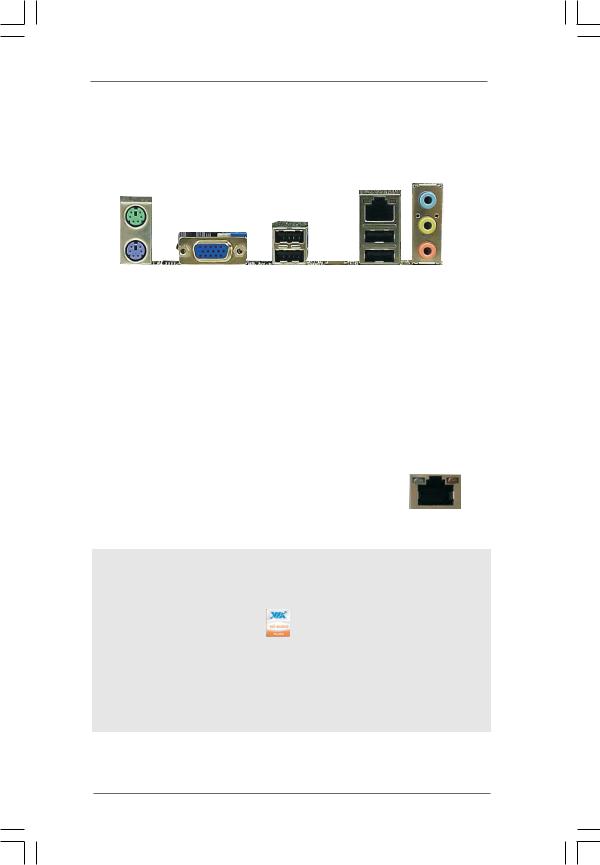
1.5 I/O Panel (G41M-VS3)
|
1 |
|
|
|
|
|
|
|
|
|
|
|
2 |
|
|
|
|
|
|
|
|
|
|
||||
|
|
|
|
|
|
|
|
|
|
|
|
|
|
|
|
|
|
|
|
|
|
|
|
|
3 |
||
|
|
|
|
|
|
|
|
|
|
|
|
|
|
|
|
|
|
|
|
|
|
|
|
|
|||
|
|
|
|
|
|
|
|
|
|
|
|
|
|
|
|
|
|
|
|
|
|
|
|
|
|||
|
|
|
|
|
|
|
|
|
|
|
|
|
|
|
|
|
|
|
|
|
|
|
|
|
|||
|
|
|
|
|
|
|
|
|
|
|
|
|
|
|
|
|
|
|
|
|
|
|
|
|
4 |
||
|
|
|
|
|
|
|
|
|
|
|
|
|
|
|
|
|
|
|
|
|
|
|
|
||||
|
|
|
|
|
|
|
|
|
|
|
|
|
|
|
|
|
|
|
|
|
|
|
|
|
|
|
5 |
|
|
|
|
|
|
|
|
|
|
|
|
|
|
|
|
|
|
|
|
|
|
|
|
|
|
|
|
|
|
|
|
|
|
|
|
|
|
|
|
|
|
|
|
|
|
|
|
||||||||
|
9 |
8 |
|
|
7 |
6 |
|
|
|
|
|
|
|||||||||||||||
1 |
PS/2 Mouse Port (Green) |
|
6 |
|
USB 2.0 Ports (USB01) |
|
|
|
|
|
|||||||||||||||||
* 2 |
RJ-45 Port |
|
7 |
|
USB 2.0 Ports (USB23) |
|
|
|
|
|
|||||||||||||||||
3 |
Line In (Light Blue) |
|
8 |
|
VGA Port |
|
|
|
|
|
|||||||||||||||||
4 |
Line Out (Lime) |
|
9 |
|
PS/2 Keyboard Port (Purple) |
||||||||||||||||||||||
5 |
Microphone (Pink) |
|
|
|
|
|
|
|
|
|
|
|
|
|
|
|
|
|
|
|
|
||||||
|
|
|
|
|
LAN Port LED Indications |
|
|
|
|
|
|
ACT/LINK SPEED |
|||||||||||||||
|
Activity/Link LED |
|
SPEED LED |
|
|
|
|
|
|
||||||||||||||||||
|
|
|
|
|
|
|
|
|
LED |
|
LED |
||||||||||||||||
Status |
|
Description |
|
Status |
|
Description |
|
|
|
|
|
|
|
|
|||||||||||||
|
|
|
|
|
|
|
|
|
|
|
|
|
|
|
|
|
|||||||||||
|
|
|
|
|
|
|
|
|
|
|
|
|
|
|
|||||||||||||
Off |
|
|
No Activity |
|
Off |
|
10Mbps connection |
|
|
|
|
|
|
|
|
|
|
||||||||||
|
|
|
|
|
|
|
|
|
|||||||||||||||||||
Blinking |
|
Data Activity |
|
Green |
|
100Mbps connection |
|
|
|
|
|
|
|
|
|
|
|||||||||||
|
|
|
|
|
|
|
|
|
|
|
|
|
|
|
|
|
|
|
|
|
|
|
|
|
|
|
|
LAN Port
To enable Multi-Streaming function, you need to connect a front panel audio cable to the front panel audio header. After restarting your computer, you will find “VIA HD Audio Deck” tool on your system. Please follow below instructions according to the OS you install.
For Windows® XP / XP 64-bit OS: |
|
Please click “VIA HD Audio Deck” icon |
, and click “Speaker”. Then you are allowed to |
select “2 Channel” or “4 Channel”. Click “Power” to save your change.
For Windows® 7 / 7 64-bit / VistaTM / VistaTM 64-bit OS:
Please click “VIA HD Audio Deck” icon  , and click “Advanced Options” on the left side
on the bottom. In “Advanced Options” screen, select “Independent Headphone”, and click “OK” to save your change.
1 3
Chapter 2 Installation
G41M-VGS3 / G41M-VS3 is a Micro ATX form factor (8.9" x 6.7", 22.6 x 17.0 cm) motherboard. Before you install the motherboard, study the configuration of your chassis to ensure that the motherboard fits into it.
Make sure to unplug the power cord before installing or removing the motherboard. Failure to do so may cause physical injuries to you and damages to motherboard components.
2.1 Screw Holes
Place screws into the holes indicated by circles to secure the motherboard to the chassis.
Do not over-tighten the screws! Doing so may damage the motherboard.
2.2 Pre-installation Precautions
Take note of the following precautions before you install motherboard components or change any motherboard settings.
1.Unplug the power cord from the wall socket before touching any component.
2.To avoid damaging the motherboard components due to static electricity, NEVER place your motherboard directly on the carpet or the like. Also remember to use a grounded wrist strap or touch a safety grounded object before you handle components.
3.Hold components by the edges and do not touch the ICs.
4.Whenever you uninstall any component, place it on a grounded antistatic pad or in the bag that comes with the component.
Before you install or remove any component, ensure that the power is switched off or the power cord is detached from the power supply.
Failure to do so may cause severe damage to the motherboard, peripherals, and/or components.
1 4
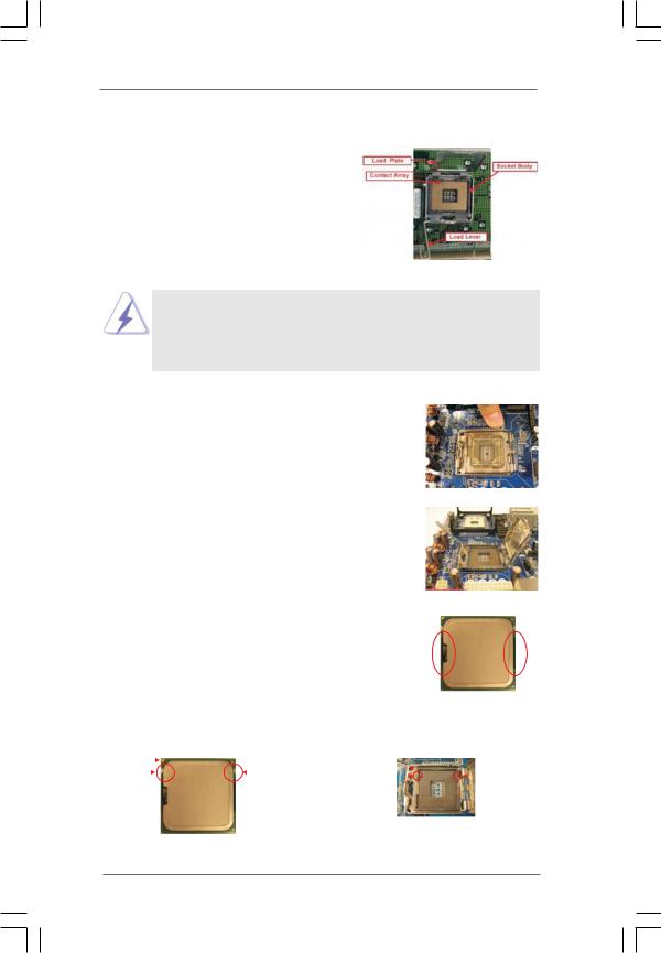
2.3 CPU Installation
For the installation of Intel 775-LAND CPU, please follow the steps below.
775-Pin Socket Overview
Before you insert the 775-LAND CPU into the socket, please check if the CPU surface is unclean or if there is any bent pin on the socket. Do not force to insert the CPU into the socket if above situation is found. Otherwise, the CPU will be seriously damaged.
Step 1. Open the socket:
Step 1-1. Disengaging the lever by depressing down and out on the hook to clear retention tab.
Step 1-2. Rotate the load lever to fully open position at approximately 135 degrees.
Step 1-3. Rotate the load plate to fully open position at approximately 100 degrees.
Step 2. Insert the 775-LAND CPU:
Step 2-1. Hold the CPU by the edges where are marked with black lines.
Step 2-2. Orient the CPU with IHS (Integrated Heat Sink) up. Locate Pin1 and the two orientation key notches.
lineblack |
lineblack |
Pin1 |
|
|
|
|
|
Pin1 |
|
|
|
|
alignment key |
||
|
|
|
|
|
|
|
|
|
|||||
|
|
|
|
|
|
|
|
|
|
|
|||
|
|
|
|
|
|
|
alignment key |
|
|
|
|
|
|
orientation |
orientation |
|
|
|
|
|
|||||||
|
|
|
|
|
|||||||||
|
|
|
|
|
|
|
|||||||
key notch |
key notch |
|
|
|
|
|
|
|
|||||
|
|
|
|
|
|
|
|
|
775-Pin Socket |
||||
|
|
|
|
775-LAND CPU |
|
|
|
|
|
|
|
||
1 5
For proper inserting, please ensure to match the two orientation key notches of the CPU with the two alignment keys of the socket.
Step 2-3. Carefully place the CPU into the socket by using a purely vertical motion.
Step 2-4. Verify that the CPU is within the socket and properly mated to the orient keys.
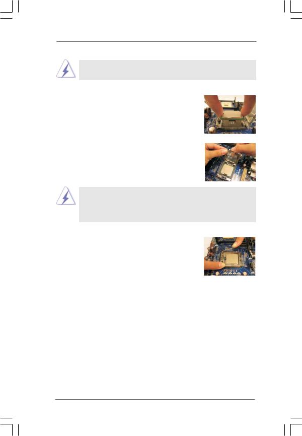
Step 3. Remove PnP Cap (Pick and Place Cap):
Use your left hand index finger and thumb to support the load plate edge, engage PnP cap with right hand thumb and peel the cap from the socket while pressing on center of PnP cap to assist in removal.
1.It is recommended to use the cap tab to handle and avoid kicking off the PnP cap.
2.This cap must be placed if returning the motherboard for after service.
Step 4. Close the socket:
Step 4-1. Rotate the load plate onto the IHS. Step 4-2. While pressing down lightly on load
plate, engage the load lever.
Step 4-3. Secure load lever with load plate tab under retention tab of load lever.
1 6
 Loading...