


 Loading...
CoreBuilder® 5000 SwitchModule
®Quick Start and Reference
1.0Introduction
The 3Com CoreBuilder® 5000 SwitchModule is a LAN switching module for the CoreBuilder 5000 Integrated System Hub. The SwitchModule is available in several media configurations and in single-slot and dual-slot models.
Before you unpack the SwitchModule, read Section 3.0, "Installation Prerequisites" and Section 5.0, "Installation Precautions".
WARNING: CoreBuilder 5000 SwitchModules must be installed only by trained service personnel.
2.0Learning About SwitchModules
This document provides the basic information that you need to install and configure a 3Com CoreBuilder 5000 SwitchModule at software Version v3.0.
For more detailed information about using the SwitchModule, see the following documents:
■CoreBuilder 5000 SwitchModule User Guide
■CoreBuilder 5000 Distributed Management Module User Guide for software Version v6.00 or later
■CoreBuilder 5000 Distributed Management Module Commands Guide for software Version v6.00 or later
You can view these documents online with the 3Com DocsOnCD documentation CD-ROM that comes with this product.
To order hard-copy documents, contact your network supplier, or call 3Com Corporation at 1-800-724-2447 and choose the Customer Operations option.
3.0Installation Prerequisites
Before you begin the SwitchModule installation process, read the hardware and software requirements in this section.
In addition to reading this document, be sure to read the Release Note for CoreBuilder 5000 SwitchModules.
3.1Tools Required
You need a flat-blade screwdriver to install the CoreBuilder 5000 SwitchModule in the hub.
3.2Hardware Prerequisites
1Ensure that the CoreBuilder 5000 hub has at least one of the following management modules installed:
■6000M-MGT Distributed Management Module, Version v6.00 or later
■6000M-CMGT Advanced DMM/Controller Module, Version v6.00 or later
2Ensure that the CoreBuilder 5000 hub has the following controller module installed: 6000M-RCTL Controller Module, Version v1.15 or later
Part Number 10013592
2 |
COREBUILDER® 5000 SWITCHMODULE QUICK START AND REFERENCE |
3Ensure that the CoreBuilder 5000 hub contains either a PacketChannel or a SwitchChannel backplane.
To verify that the hub has one of these backplanes, enter the command SHOW HUB. The model number displayed in the Hub Type field should end in C (SwitchChannel) or P (PacketChannel), and one of these backplanes should be listed under Backplane Type.
For example:
> show hub |
|
Hub Information: |
|
Hub Type: 6017C-AC |
|
Backplane Information: |
|
Backplane Type |
Revision |
-------------- |
-------- |
Load-Sharing Power Distribution module 0 |
|
Enhanced TriChannel Backplane |
1 |
RingChannel Backplane |
0 |
SwitchChannel Backplane |
2 |
3.3Software Prerequisites
Before you install a new SwitchModule:
1Determine the DMM module’s software version status. Enter the SHOW MODULE ALL command.
> show module all
The following display appears:
Slot |
Module |
Version |
Network |
General Info |
----- |
------- |
------- |
-------- |
------------- |
10.01 |
6100D-MGT |
v1.00 |
ETHERNET_1 |
|
11.01 |
6000M-RCTL |
v1.15 |
N/A |
Active |
|
|
|
|
Ctrl Module |
12.01 |
6000M-ARCTL |
v1.15 |
N/A |
Stndby Ctrl |
|
|
|
|
Module |
12.02 |
6000M-AMGT |
v6.00 |
N/A |
Master Mgmt |
|
|
|
|
Module |
If your hub does not have an installed PacketChannel or SwitchChannel backplane and you require communication among SwitchModules, contact 3Com or your 3Com representative to order a backplane upgrade kit.
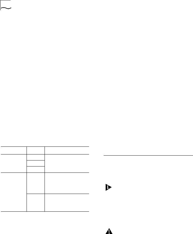
4Use the following table to determine the slot restrictions that apply to your hub configuration:
Backplane Type |
Hub Type |
Installation Guideline |
PacketChannel |
17-Slot |
Install SwitchModules in any |
|
10-Slot |
slot. |
|
|
|
|
7-Slot |
|
SwitchChannel |
17-Slot |
Slots 9, 10, 11, and 12 are |
(PacketChannel |
|
reserved for the |
plus ATM |
|
CoreBuilder® 5000 ATM |
Cell-Switching) |
|
Switch/Control Point Module |
|
|
(Model Number 3C96416SW). |
|
10-Slot |
Slots 9 and 10 are reserved for |
|
|
the CoreBuilder 5000 ATM |
|
|
Switch/Control Point Module |
|
|
(Model Number 3C96416SW). |
If you are installing only one SwitchModule, you can install it in any slot, including a reserved ATM slot. The single SwitchModule acts as a stand-alone switch.
If your hub does not have an installed PacketChannel or SwitchChannel backplane, you can install only one SwitchModule per hub.
2Look in the Version column to get the DMM software version. The new SwitchModule functions incorrectly if the DMM software version is wrong.
As shown in the previous display example, the Advanced DMM/Controller (Model
Number 6000M-CMGT) appears as two modules in the same slot (Model Numbers 6000M-ARCTL and 6000M-AMGT). The DMM operational code version is displayed in the Version field of the -AMGT module.
4.0Crucial Download Procedure
Review the following procedures before you attempt to download software to any SwitchModule in your hub.
You must use the following procedures if you have 66xx family SwitchModules installed in your hub.
4.1Download Procedure for SwitchModules Earlier than Version v2.02 and DMMs Earlier than Version v5.00
Use the following procedure for all SwitchModules in your hub that are earlier than Version v2.02, and DMMs that are earlier than Version v5.00.
CAUTION: All bridge port communication ceases if you use an incorrect download procedure to upgrade your SwitchModule and Distributed Management Module (DMM) and Advanced DMM (A/DMM) software. If you use an IP relay for connectivity to download code to the DMM, that connection also stops.
COREBUILDER® 5000 SWITCHMODULE QUICK START AND REFERENCE |
3 |
For ease of reading and because the DMM and A/DMM are basically the same, the term DMM is used in this release note to refer to both modules.
CAUTION: Do not upgrade to any later version until instructed to do so in Step 5.
See the CoreBuilder 5000 Distributed Management Module User Guide, Chapter 11, for information about DMM downloading.
CAUTION: Do not install the new SwitchModules yet.
1Upgrade all DMMs in the hub to software Version v5.00.
2Download SwitchModule boot software Version v1.05 to all SwitchModules in your hub.
3Download ATM SwitchModule software Version v3.00 operational code to all ATM Backbone SwitchModules in the hub. The ATM SwitchModule model number is 3C96602M-MOD.
4Upgrade all DMMs in the hub to software Version v6.00.
5Install the new SwitchModule into your hub. (See Section 7.0, "Installing the SwitchModule".)
6Download the Version v3.00 software code to the new SwitchModule.
To use the Frame Tagging feature, you must upgrade all SwitchModules in the hub to software Version v3.00 or later.
3Download SwitchModule software Version v3.00 to all SwitchModules in your hub, even if they are already running Version v3.00.
4Download ATM Backbone SwitchModule software Version v2.05 boot code, and then Version v3.00 operational code to all ATM Backbone SwitchModules in your hub. The Model Number is 3C96602M-MOD.
5Upgrade all DMMs in your hub to software Version v6.00.
6Install the new SwitchModule into your hub. (See Section 7.0, "Installing the SwitchModule".)
7Download the Version v3.00 software code to the new SwitchModule.
To use the Frame Tagging feature, you must upgrade all SwitchModules in the hub to software Version v3.00 or later.
4.2Download Procedure for SwitchModules at Version v2.02 or Later and DMMs at Version v5.00 or Later
If your hub contains any SwitchModules that are at Version v2.02 or later, and DMMs at Version 5.00 or later, complete the following download procedure:
CAUTION: Do not install the new SwitchModules yet.
1Download SwitchModule boot software Version v1.05 to all SwitchModules in the hub.
2Download SwitchModule software Version v3.00 operational code to all SwitchModules in the hub.
5.0Installation Precautions
Electrostatic discharge (ESD) can damage static-sensitive devices on circuit modules. Follow these precautions:
■Do not remove the SwitchModule from its antistatic bag until you are ready to inspect or to install it.
■Handle the SwitchModule by the front panel only; do not hold it by the component board.
■Use proper grounding techniques when you install the SwitchModule. These techniques include using a foot strap and a grounded mat, wearing a grounded static discharge wrist strap, or touching the metal rack or frame just before you handle the SwitchModule.
When you handle CoreBuilder 5000 SwitchModules, follow these precautions to avoid component damage:
■Do not twist or force the SwitchModule into the hub when you insert it into the module guides.
■Match the upper and lower module guides while you slide the SwitchModule into place.
■Do not push the SwitchModule all the way into the hub until the SwitchModule ejectors (if any) are open.
WARNING: To ensure optical safety when you install 10BASE-FB/FL, FDDI, and 100BASE-FX SwitchModules, comply with the following precaution:
Although the data communication LEDs and Lasers used in this product meet the regulatory requirements for casual exposure to the eye, as with any source of bright light, it is advised that you do not look into the light source.
4 |
COREBUILDER® 5000 SWITCHMODULE QUICK START AND REFERENCE |
IEC 825, Class 1 LED Device. For connection only to Class 1 LED Devices.
CLASS 1
LED PRODUCT
6.0Unpacking Procedure
Follow this procedure to unpack a SwitchModule:
1Verify that the SwitchModule is the model that you ordered by examining the model number on the side of the shipping carton.
2Remove the SwitchModule, in its antistatic bag, from the shipping carton.
3Following the instructions in Section 5.0, "Installation Precautions", remove the SwitchModule from the antistatic bag and inspect it for damage.
If the SwitchModule appears to be damaged, return it to the antistatic bag, repack it in the shipping carton, and contact your local supplier.
Keep the shipping carton and antistatic bag in which your SwitchModule was shipped for future storage or shipment.
4Record the serial number of your SwitchModule. Use the CoreBuilder 5000 SwitchModule Planning Chart that comes with this product.
5Ensure that the CoreBuilder 5000 SwitchModule Kit contains these items:
■CoreBuilder 5000 SwitchModule
■Release Note for CoreBuilder 5000 SwitchModules
■3Com DocsOnCD documentation CD-ROM (contains
CoreBuilder 5000 SwitchModule User Guide)
■CoreBuilder 5000 SwitchModule Quick Start and Reference (this guide)
■CoreBuilder 5000 SwitchModule Command Reference
■CoreBuilder 5000 SwitchModule Planning Chart
7.0Installing the SwitchModule
You do not need to turn off the CoreBuilder 5000 hub to install or remove the SwitchModule. You can install the SwitchModule while the hub is operating (which is called a hot swap).
Before you start the installation process, read Section 3.3, "Software Prerequisites," and Section 5.0, "Installation Precautions".
To install a SwitchModule:
1Determine hub power. To ensure that the hub has enough power to support the new SwitchModule:
a Enter the SHOW POWER BUDGET command to see if sufficient wattage is available from the +5 volt,
–5 volt, and +12 volt supplies.
b Using the values in the following table, add up the total power requirements for the SwitchModules that you plan to install:
|
Power Requirement at |
|||
Model Number |
+5 Volts |
–5 Volts |
+12 Volts |
|
|
|
|
|
|
3C96618M-TX-A |
52 W |
0.5 W |
0.25 Watts |
|
|
|
|
for all |
|
3c96620M-TP-A |
25 W |
0.5 W |
||
modules |
||||
|
|
|
|
|
3C96612M-TP-A |
23 W |
0.5 W |
|
|
|
|
|
|
|
3C96624M-TP-A |
30 W |
0.5 W |
|
|
|
|
|
|
|
3C96624M-TPL-A |
25 W |
0.5 W |
|
|
|
|
|
|
|
3C96616M-BTP-A |
35 W |
1.0 W |
|
|
|
|
|
|
|
3C96610M-F-A |
33 W |
0.5 W |
|
|
|
|
|
|
|
3C96620M-F-A |
50 W |
0.5 W |
|
|
|
|
|
|
|
3C96614M-FTP-A |
30 W |
0.5 W |
|
|
|
|
|
|
|
3C96612M-FF-A |
40 W |
0.5 W |
|
|
|
|
|
|
|
3C96604M-F-A |
31 W |
0.5 W |
|
|
|
|
|
|
|
3C96612M-FC-A |
57 W |
0.5 W |
|
|
|
|
|
|
|
3C96604M-TX-A |
34 W |
0.5 W |
|
|
|
|
|
|
|
3C96604M-FX-A |
35 W |
0.5 W |
|
|
|
|
|
|
|

COREBUILDER® 5000 SWITCHMODULE QUICK START AND REFERENCE |
5 |
cThe total watts that are available in the hub (from step a) must be greater than the total watts that are required by the SwitchModules (from step b). Use the following worksheet to calculate power consumption:
Voltage |
Watts |
|
Watts |
Watts |
|
Available |
|
Required by |
|||
Category |
– |
= Remaining |
|||
in Hub |
SwitchModule |
||||
+5 |
|
– |
|
= |
|
–5 |
|
– |
|
= |
|
+12 |
|
– |
|
= |
2To expose slots for SwitchModule installation, remove as many blank faceplates from the chassis as required.
WARNING: Hazardous energy levels exist inside of the hub. Do not place hands or objects into the hub or touch components on an inserted module.
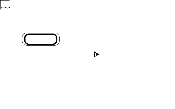
3Insert each SwitchModule into the module guides at the top and bottom of the selected slot and slide it into the chassis by pressing firmly at the top and bottom of the front panel (see the figure at right).
4Lock the SwitchModules into place by applying pressure to the front panel with one hand while you close each ejector handle. Ensure that the SwitchModule remains fully seated in the backplane connector while you close the ejector handles.
5To secure the SwitchModule front panel to the front of the chassis, use a flat-blade screwdriver to tighten the top and bottom screws to torque specification
3 to 5 inch pounds. Do not overtighten.
WARNING: For safety reasons and to ensure adequate cooling airflow, install blank faceplates over all empty slots.
Slide the SwitchModule into the
selected slot as shown here.
6To ensure that the DMM recognizes the installed SwitchModule, enter the SHOW MODULE ALL command. Verify that the model number of the SwitchModule appears in the correct slot.
There may be a delay (no more than 30 seconds) before the DMM recognizes the SwitchModule.
7Ensure that the hub is operating with enough power by entering the SHOW POWER BUDGET command.
Loading...