


FAN-DS-2
FAN-DS-2
August 2000
Model Q™ Fans
Sizes 16 through 60
Super Q II Fans
Sizes 16 through 44
Model Q Fans
Sizes 16 through 60
Super Q II Fans
Sizes 16 through 44

Features
and Benefits
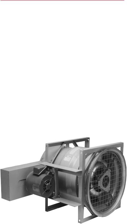
Q Fan
The Model Q™ fan is a quiet, airfoil, inline fan specifically designed for air conditioning applications. This highly refined axial flow fan is available in 13 sizes from 1,000 through 80,000 cfm. Small and compact, the Q fan has proven to be the ideal air moving device for standalone applications and also for custom air handling units. It can be used for supply, return and exhaust systems.
Available in arrangement 1 (for floor mounting of larger units with heavier motors) and arrangement 9 (horizontal or vertical mounting), it can be selected in class 1, 2 and 3. Arrangement 9 permits factory mounting of the motor on top, bottom, or either side of the fan
— see below.
Benefits
•The Q (Quiet) Fan
TheTrane Model Q fan generates less low frequency noise (more difficult to attenuate) than any other type of fan in the HVAC industry. Sound level comparisons show common vaneaxial fans produce up to 23 db higher sound levels than the Model Q — significant in industrial applications. Being quieter than centrifugal fans allows for installations closer to building occupants.
•Saves Mechanical Room Space
The compact quiet Q fan saves floor space, which reduces system first cost.
•EasyTo Install
Rigging and installation is so much quicker and easier that total installed cost savings are typically five percent or more.
•Low Maintenance
Belt-driven with fixed blades, Model Q fan has very few moving parts. This design results in exceptionally low maintenance requirements. No fan teardowns need be scheduled. In fact, Q fans installed 25 years ago are still operating just as quietly as when they were installed.
•Flexible Installation
The Model Q arrangement 9 can be set in any position, for horizontal discharge, angled discharge and vertical discharge either upblast or downflow.The only limitations placed on this arrangement are those dictated by good fan installation practice.
•Motor slide rails and drive guard are standard, at no extra cost.
Discharge End View
Arrangement 9 |
Arrangement 1 |
AMCA Licensed Ratings
TheTrane Company certifies that the Model Q fans shown herein are licensed to bear the AMCA Seal. The ratings shown are based on tests and procedures performed in accordance with AMCA Publication 211 and comply with the requirements of the AMCA Certified Ratings Program.
©American Standard Inc. 2000 |
2 |
Contents
Q Fan Accessories
•Inlet flange — for simplified, rigid connection of ductwork to inlet end of fan
•Inlet screen — safety accessory mounted to fan inlet. Heavy, plated steel wire
Note: inlet screen and inlet flange are mutually exclusive.
•Inlet vanes — mechanically modulate fan capacity
•Inlet bellmouth — used with unducted or plenum applications. Improves air flow and reduces noise.
•Inlet silencer (long or short) — flex connected to Q fan
•Outlet flange — for simplified, rigid connection of ductwork to outlet end of fan
•Outlet screen — safety accessory mounted to fan outlet. Heavy, plated steel wire
Note: outlet screen and outlet flange are mutually exclusive.
•Outlet duct diffuser (equalizer) — makes fan outlet diameter equal to inlet diameter
•Outlet flow stabilization screen — small mesh outlet screen. Helps offset effect of poor outlet airflow conditions
•Outlet silencer (short or long) — flex connected to Q fan
•Vertical mounting legs — used with arrangement 9 for vertical discharge floor and ceiling mounted
•Isolators — to eliminate vibrations for
floor, ceiling and vertical installations |
|
•Special coatings — to protect against |
|
alkyds, acids and corrosive |
|
environments |
|
•Access door — available on sizes 49, 54 |
|
and 60 for easier service |
|
•Drain — recommended to drain off the |
|
condensate where moisture-laden air is |
|
exhausted |
|
•Copper grease lines — plastic lines are |
|
standard |
|
•Double acoustic enhancement — |
|
insulation and perforated sheet metal |
|
to attenuate radiated sound |
|
•Fan insulation — self-adhesive foam, |
|
applied on the outside of the fan shell |
|
to protect against moisture |
|
•Variable frequency inverter balancing |
|
and reinforcement (frequency inverter |
|
by others). This option requires |
|
constant pitch drives. |
Model Q Fan — Arrangement 9 |
Features and Benefits |
2 |
|
|
Model Number Description |
12 |
|
|
Application Considerations |
13 |
|
|
Selection Procedure |
21 |
|
|
Performance Data |
22 |
|
|
Dimensional Data and Weights |
48 |
|
|
Mechanical Specifications |
54 |
|
|
3
Features
and Benefits
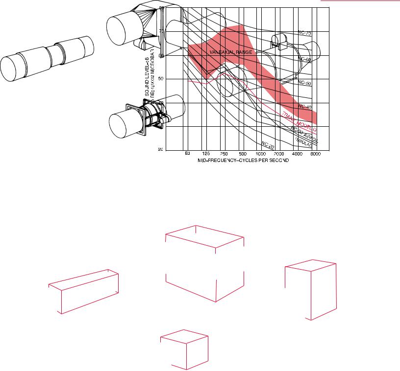
This chart shows a typical NC level comparison between common vaneaxials, tubular centrifugals, airfoil centrifugals and theTrane Model Q™ compact fan. The shaded area represents range of vaneaxials tested.
Trane Model Q fans require up to
85 percent less cubic space than airfoil centrifugal fans and 40 percent less than common vaneaxials of equivalent installed sound level. Floor space savings can be as much as 65 percent when compared to the common vaneaxial and airfoil centrifugal and 40 percent when compared to tubular centrifugals.
Airfoil Centrifugal Fan
Vaneaxial Fan
Tubular Centrifugal Fan
Trane Model Q Compact Fan
4
Features
and Benefits
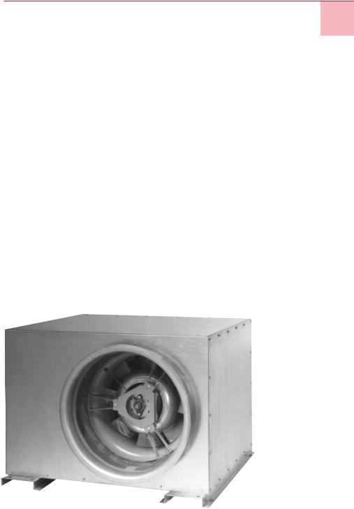
Super Q II Plus
More than twenty years after the introduction of the Model Q™, it still retains its reputation as one of the quietest HVAC fans in the world.This tradition of excellence continues with the introduction of a new Q fan acoustical enclosure and duct silencer so effective and so compact that we named it the Super Q II.
Super Q II Fan
Available with Model Q fans from 1,000 to 43,000 cfm, the Super Q II enclosure inhibits radiated fan and motor noise from entering the surrounding space. It internally isolates the fan on high deflection spring isolators so ductwork can be connected directly to the enclosure. It is uniquely designed to be floor or ceiling mounted with ease.
Although the Model Q needs very little maintenance, future maintenance requirements were considered by Super Q II designers. Every unit has the bearing grease lines extended through the casing and every unit has two full size access panels that provide complete access to all internal components.
Variable Air Volume Compatible
The Super Q fan is modulated forVAV with variable frequency drives (by others), not with inlet vanes. Variable speed inverter fan modulation offers exceptional energy saving and exceptionally quiet part load operation. VAV variable speed Q fans are structurally reinforced to handle the uneven harmonic loadings associated with variable speed fan operation. In addition, the factory gives variable speed Q fans a precise, 10-point balance to further help assure troublefree operation. Only constant pitch drives should be used with variable frequency inverters.
Super Q II Accessories
•Inlet screen — safety accessory mounted to fan inlet. Heavy, plated steel wire
•Inlet bellmouth — used with unducted or plenum applications. Improves air flow and reduces noise.
•Inlet silencer (long or short) — rigid connection to Super Q fan
•Outlet flow stabilization screen — small mesh outlet screen. Helps offset effect of poor outlet airflow conditions
•Outlet silencer (short or long) — flex connected to Q fan
•Variable frequency inverter balancing and reinforcement (frequency inverter by others). This option requires constant pitch drives.
•Outlet screen — safety accessory mounted to fan outlet. Heavy, plated steel wire.
Super Q II
5
Features
and Benefits
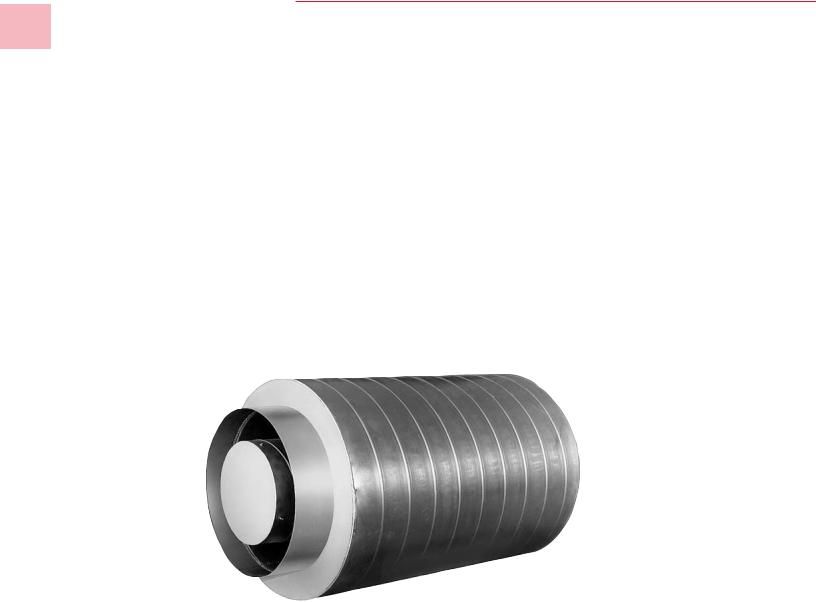
Trane Plus Duct Silencer
The Plus option is a high performance duct silencer. Designed specifically for the Super Q II and Model Q™, it has several unique features that reduce airborne noise and turbulence to exceptionally low levels. Briefly, the Plus option develops maximum static regain while simultaneously limiting objectionable mid and high frequency noise. The Plus option should be used whenever quiet comfort is desired and the duct system is acoustically unable to provide it.
Trane’s Plus Silencer provides significant noise attenuation, up to
32 db at 1,000 Hz, without a significant increase in fan horsepower requirements.
By carrying the concept of noise source attenuation to its economic maximum, Trane has created a fan system that can move significant amounts of air without creating objectionable low frequency rumble. It provides proven acoustical performance with less design risk. In project after project, the Trane Model Q fan has been the key to creating NC 15 to NC 35 quiet comfort jobs.
Beyond quiet, the Super Q II Plus system is small and compact. In fact, it is small and quiet enough that it can be successfully installed in ceiling plenums. Locating a Super Q II Plus in the plenum helps reduce and even eliminate the floor space needed for the mechanical room.
The modular, component design approach of the Super Q II air handling system makes it exceptionally well suited for renovation, retrofit and replacement projects. The Super Q II air handling system components (fan, silencers, filter/coil module, etc.) fit through most doors and elevators and can be easily field-assembled into any system configuration (blow-thru, drawthru, etc.).
Plus Silencer
6
Features
and Benefits
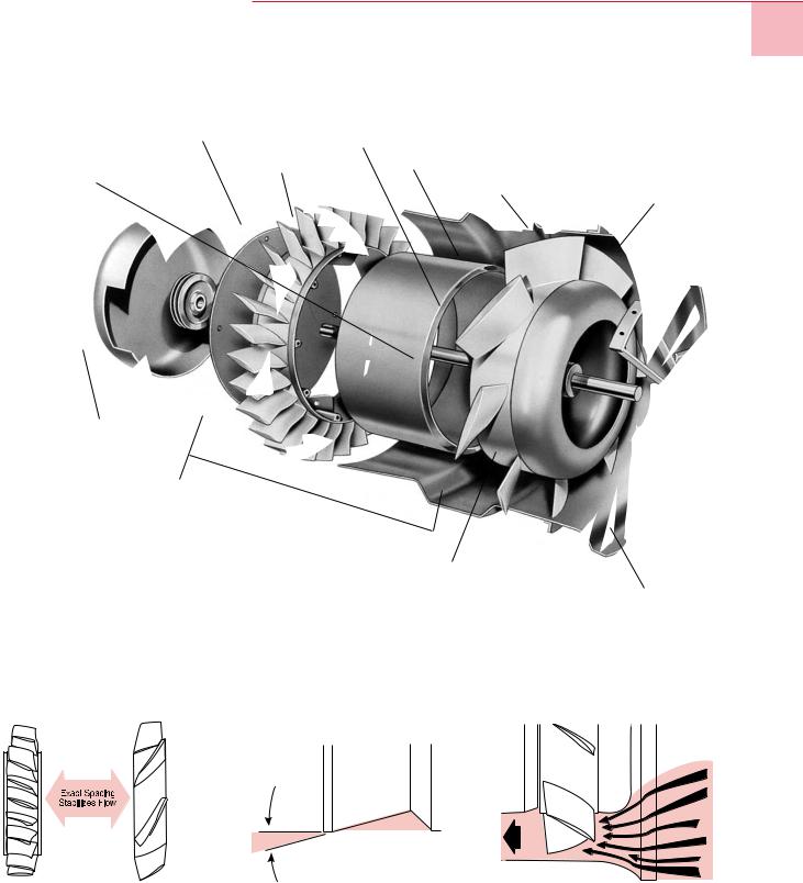
Low Sound Level, High Efficiency
Provided by Unique Aerodynamic
Features
[9] Airfoil Vanes (stationary)
[4] Airfoil Blade Wheel. |
|
[10] Stabilizing Pitch |
[5] Aerodynamic Pitch |
[7] Hub Streamlining Insulation
[6] MinimumTip Clearance
[2] Aerodynamic Inlet Bell
[12]End Cone
[8]Exact Blade toVane Spacing
[11]Precise Divergent Angle Diffuser Discharge Cone
[3] Aerodynamic Inlet Cone
[1] Thin Strut Patented Bearing Support
Precision cast fan wheel and diffuser for highly efficient aerodynamic performance. [8]
Precise divergent angle for maximum |
Aerodynamic inlet provides smooth |
static regain. [11] |
airflow. [3] |
Note: Call-out numbers shown above are referenced on page 8.
7

Features
and Benefits
The low sound and high performance of theTrane Model Q™ fan are achieved by reducing noise-creating, energyconsuming turbulence within the fan. Airflow research and development techniques employed were similar to those used in perfecting today’s high performance axial flow jet engine compressors. The resulting smooth air path has made the Model Q the first vaneaxial fan to provide quiet, efficient operation, suitable for air conditioning duty.
Aerodynamic Air Path
A component by component analysis of the Model Q points to 12 aerodynamic features which are keys to a smooth air path. Starting at the inlet, the struts [1] of the patented bearing support are precisely positioned in relation to the fan blades. Air passing over the struts strikes the blades in a pattern that prevents blade whine.
The aerodynamically shaped inlet bell [2] and inlet cone [3] provide uniform axial flow parallel to the fan shaft. Air is delivered equally to the leading edge of the fan blades — no crowding toward the fan tips.
Air separation is reduced by the precision cast aluminum airfoil cross section [4] of the fan blades. Blade pitch [5], using a variable angle of attack in the radial dimensions, is precisely controlled to prevent energy loss. Exceptionally close clearance
[6]between the blade tips and housing reduces the eddy currents of fan tip recirculation. The reinforcing ring rigidizes the housing to maintain the tip clearance. The interior of the fan wheel is insulated to prevent hub strengthening protrusions from
[7]windmilling in the airstream.
A precisely controlled space [8] between the fan blades and diffuser vanes is necessary to allow airflow
stabilization ahead of the vanes. The vanes themselves are precision cast aluminum and have an airfoil cross section [9] and a precise radial pitch [10]. This provides smooth, spiral-free discharge.
The diffuser section design [11] is critical. A precisely determined diffusion angle produces the greatest possible static regain within the confines of the fan. An end cone [12) covers the fan drive assembly, thereby reducing the turbulence
generated by air passing over exposed drives.
Precise Manufacturing Assures Performance — Advanced manufacturing techniques assure the same performance characteristics for each production Model Q fan.
•Fin Struts — The fin struts of the patented bearing support are precisely positioned in relation to the fan blade. Air passing over the struts strikes the plate in a pattern that prevents the irritating whine, from blade frequency, which is characteristic of industrial vaneaxials.
•Inlet Bell and Cone — The aerodynamically shaped inlet bell and inlet cone provide uniform axial flow into the fan parallel with the fan shaft. Air is delivered equally to the leading edge of the fan blades. This prevents crowding toward the blade tip.
•Wheel — The wheel consists of 8 precision cast blades with a twisted radially projected shape and airfoil cross section. This radial projection utilizes a variable angle of attack in the radial dimension and prevents radial movement as the air particles move through the wheel.
•Tip Clearance — Close clearance between the blade tips and housing reduces eddy currents due to tip recirculation. The reinforcing ring holds the housing in its precise shape to maintain proper clearance.
•Vane Spacing — Precise space between the fan blades and the diffuser vanes is necessary to allow flow stabilization ahead of the vanes. The 29 diffuser vanes also have an airfoil cross section and a twisted, radially projected shape. This provides smooth, spiralfree air discharge.
•Precision Cast Aluminum Fan and Diffuser — Being cast, blade and vane shapes are permanently and precisely fixed. They are not subject to misalignment or distortion as are welded, sheet metal forms.
•Diffuser Section — The diffuser section design is critical. A precisely determined flare angle at the diffuser end produces the greatest possible static regain within the confines of the fan. Thus, externally mounted diffuser accessories, common for industrial vaneaxials, are not necessary.
•Hydraulically Expanded FlowFormed Housing — In this process, the cylindrical housing is drawn to its final form over an expansion die. The metal, expanded beyond its elastic limit, permanently retains the precision form imparted by the die.
•Ductile Weld Technique — This technique is required for the fan housing seam to guarantee success of the expansion forming process. The arc and “puddle” are submerged in molten flux that shields the weld material from oxidation. This prevents brittleness and also anneals the weld. The result is a flexible, ductile seam capable of being drawn and formed — another example of the advanced technology used in theTrane Model
Q fan.
8
Features
and Benefits
Saving Valuable
Equipment Room Space
TheTrane Model Q™ and Super Q II fans can help you maximize your building’s usable floor space by using them in place of centrifugal fans. The smaller the equipment room, the more space left for tenants, merchandise, etc.
Return or Exhaust Applications
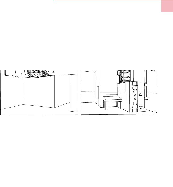
Figure F-1 shows a size 44, single width, low pressure airfoil centrifugal fan delivering 20,000 cfm of air. Because of its size and weight, it is floor mounted and connected to a return air plenum. In contrast, a 44-inch Model Q fan is used in Figure F-2 instead of a centrifugal fan. Its smaller size and lighter weight permits ceiling suspension and approximately 75 sq ft of floor space is freed up for other use.
Draw-Thru Supply Application (Small Capacity)
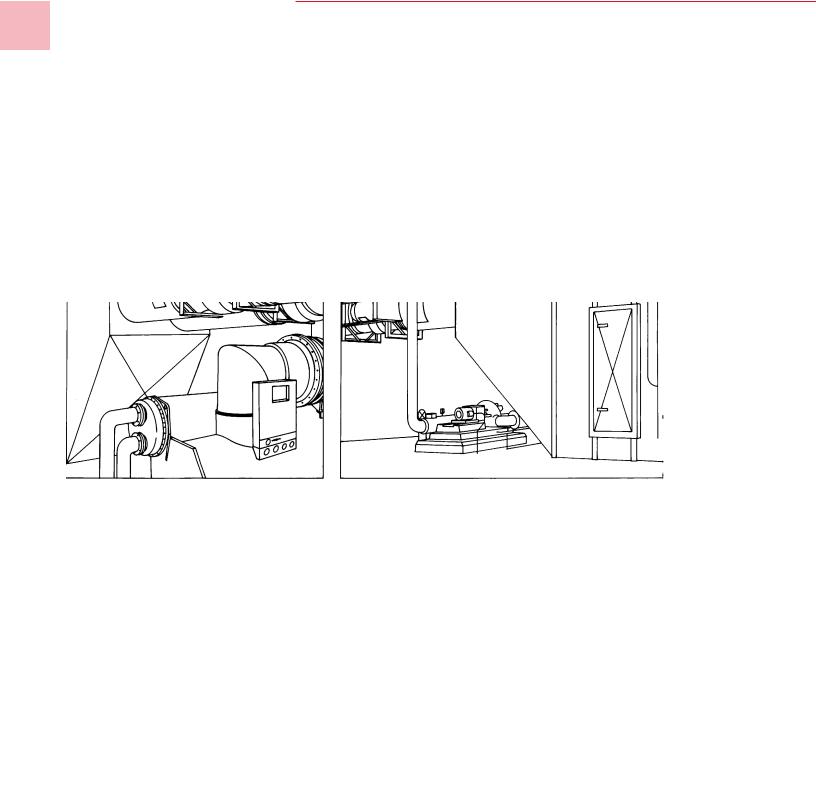
The fan system in Figure F-3 is a 27-inch, single width, medium pressure airfoil centrifugal fan rated at 9,000 cfm. Even though it is a relatively small fan, it is floor mounted beside the coil bank plenum. Figure F-4 shows a 27-inch Model Q substituted in place of the centrifugal. The small size and weight, plus the installation flexibility of the Model Q, permits mounting in a vertical position on top of the plenum. The space savings is about 25 sq ft.
Figure F-1 |
Figure F-3 |
Figure F-2 |
Figure F-4 |
9
Features
and Benefits
Draw-Thru Supply Application (Large Capacity)
A 60-inch, single-width, medium pressure airfoil centrifugal fan is used in the system illustrated in Figure F-5 to supply 45,000 cfm of air.This capacity can be easily achieved by installing a pair of 40-inch Model Q™ fans in parallel as shown in Figure F-6. The resulting floor space savings is approximately 85 sq ft!
Blow-Thru Supply Application
Figure F-7 shows a typical medium pressure, built-up, blow-thru system. The fan, enclosed in a plenum, is a 33inch, double width, airfoil centrifugal that delivers 30,000 cfm of air.The bulkiness of the plenum is dictated by the necessary clearances around the fan.To save floor space, a 44-inch Model Q replaces the centrifugal in Figure F-8. The suspended mounting of the Model Q frees about 70 sq ft for installation of pumps and other equipment.
Figure F-5 |
Figure F-7 |
Figure F-6 |
Figure F-8 |
10
Features
and Benefits
TheTrane Model Q™ fan, with all its precision and quality, is still a cost effective fan. When all necessary system components are considered, it provides substantial installation cost savings. In addition, its small size and variable mounting positions allow more freedom to the designer and installer.
First Cost Comparisons
True first cost is the total cost of an operable installation. With theTrane Model Q, this consists of only the fan, drive and isolation. By comparison, the airfoil centrifugal typically requires these three components, plus an integral base. In addition, cost of isolation for the airfoil is greater because it is typically twice as heavy as the Model Q.
The common vaneaxial also requires more components in most applications. Besides the fan, drive and isolation, an inlet bell and diffuser are frequently necessary to meet cataloged performance. A sound attenuator is also required to reduce noise to a level equivalent to a Model Q fan without attenuation.
Reduce Installed Cost
By UpTo 20 Percent
Lower Installation Costs
TheTrane Model Q fan has fewer components to install and the advantage of lighter weight. With only half the weight of airfoil and tubular centrifugals, it requires less manpower for rigging and setting the fan in place. The result is reduced labor, with corresponding dollar savings on the typical job.
Lighter weight also reduces inertia pad requirements. With the Model Q, a pad has to be considered only on large
Class III fans. Airfoil and tubular centrifugals, because of greater weight, often require pads for Class I and II to minimize the effect imposed by normal vibration.
Combined Saving Significant
A comparison of average total installed cost is shown inTable F-1. Average cost figures were developed based on estimates by experienced installing contractors. In all cases, theTrane Model Q represents a significant savings.
Table F-1 —Total Installed Cost Comparison
|
Standard |
Trane |
Tubular |
|
Item Required |
Centrifugal |
Model Q |
Centrifugal |
Vaneaxial |
First Cost Requirement |
|
|
|
|
|
|
|
|
|
Fan |
X |
X |
X |
X |
|
|
|
|
|
Belt Guard |
X |
X |
X |
|
Integral Base |
X |
|
|
|
|
|
|
|
|
Inlet Bell |
|
|
|
X |
|
|
|
|
|
Attenuation |
|
|
|
X |
Spring Isolators |
X |
X |
X |
X |
|
|
|
|
|
Installation Cost Requirements |
|
|
|
|
|
|
|
|
|
Rigging |
X |
X |
X |
X |
Install Attenuation |
|
|
|
X |
|
|
|
|
|
Mount Motor (Etc.) |
X |
|
X |
|
|
|
|
|
|
Install Isolation |
X |
X |
X |
X |
Average Total Installed Cost |
X |
–5 |
+5 |
+15 |
|
|
|
|
|
Comparison is based on equal size fans of similar capacities. The airfoil centrifugal fan is used as base (100%) for comparative purposes. Figures are based on estimates by experienced installing contractors.
Arrangement 9Trane Model Q fan requires purchase of motor, motor rails, belt guard and isolation in addition to the basic fan.
Arrangement 3 airfoil centrifugal fan requires purchase of motor, belt guard, motor slide rail, isolation and subbase in addition to basic fan.
11

|
Valid |
Select- |
|
|
Prod. |
able |
|
|
Cat. |
Item |
Description |
|
CYCLE |
QSE |
E-cycle 16-44 arr 9 cl 1&2 |
|
|||
|
|
|
w/o mtr mtd |
|
|
QSE1 |
E-cycle 16-44 arr 9 cl1&2 |
|
|
|
w/mtr mtd |
|
|
|
|
|
|
QSQ |
Q-cycle 16-44 arr 9 cl 1,2&3 |
|
|
MTO |
Std cycle 16-44 arr 1&9 |
|
|
|
cl 1,2&3 & SQ2 |
|
|
MTO1 |
Std cycle 16-44 arr 1&9 |
|
|
|
w/unit coating |
|
|
MTO2 |
Std cycle 49-60 arr 9 cl 1&2 |
|
|
MTO3 |
Std cycle 49-60 arr 9 |
|
|
|
w/unit coating |
|
MODEL QFNA |
Q (Quiet) fan |
|
|
TYPE |
SQ2 |
Super Q2 fan |
|
|
QFAN |
Q fan |
|
SIZE |
16 |
Fan size 16” (400 mm) |
|
|
19 |
Fan size 19” (475 mm) |
|
|
21 |
Fan size 21” (525 mm) |
|
|
24 |
Fan size 24” (600 mm) |
|
|
27 |
Fan size 27” (675 mm) |
|
|
30 |
Fan size 30” (750 mm) |
|
|
33 |
Fan size 33” (825 mm) |
|
|
36 |
Fan size 36” (900 mm) |
|
|
40 |
Fan size 40” (1000 mm) |
|
|
44 |
Fan size 44” (1100 mm) |
|
|
49 |
Fan size 49” (1225 mm) |
|
|
54 |
Fan size 54” (1350 mm) |
|
|
60 |
Fan size 60” (1500 mm) |
|
ARRG |
9 |
Arrangement 9 fan |
|
|
1 |
Arrangement 1 fan |
|
CLASS |
1 |
Class 1 fan |
|
|
2 |
Class 2 fan |
|
|
3 |
Class 3 fan |
|
UORT |
UP |
Upblast discharge |
|
|
DOWN Downblast discharge |
|
|
|
H |
Horizontal discharge |
|
MTRS |
TT |
Trane supplied motor & |
|
|
|
Trane mounted |
|
|
FT |
Field supplied motor & |
|
|
|
Trane mounted |
|
|
TF |
Trane supplied motor & |
|
|
|
field mounted |
|
|
FF |
Field supplied motor & |
|
|
|
field •mounted |
|
TRES |
WB |
Thrust restraints WB |
|
|
|
(direct ship) |
|
|
NONE No thrust restraints |
|
|
DUCT |
YES |
Duct canvas |
|
WBAL |
FACT |
Q fan inverter factory |
|
|
|
balancing |
|
|
FIELD |
Inverter ready balanced by |
|
|
|
customer |
Model
Number
Description
Valid Select-
Prod. able
Cat. Item Description
MTHP 1 Motor hp 1 (.7 kW) 1.5 Motor hp 1.5 (1 kW)
2Motor hp 2 (1.5 kW)
3Motor hp 3 (2 kW)
5Motor hp 5 (4 kW)
7.5 Motor hp 7.5 (5.5 kW)
10 Motor hp 10 (7 kW)
15 Motor hp 15 (11 kW)
20 Motor hp 20 (15 kW)
25 Motor hp 25 (18 kW)
30 Motor hp 30 (22 kW)
40 Motor hp 40 (30 kW)
50 Motor hp 50 (37 kW)
60 Motor hp 60 (44 kW)
75 Motor hp 75 (56 kW)
MTYP HEOP18ODP High eff mtr 1800 rpm 1S/1W
ODP12 ODP High eff mtr 1800/ 1200 rpm 2S/2W
ODP91 ODP High eff mtr 1800/ 900 rpm 2S/1W
ODP92 ODP High eff mtr 1800/ 900 rpm 2S/2W
PHOP18ODP Prem Hi E+3 mtr 1800 rpm 1S/1W
HETE18 TEFC High eff mtr 1800 rpm 1S/1W
PHTE18 TEFC Prem Hi E+3 mtr 1800 rpm 1S/1W
Valid Select- |
|
|
Prod. able |
|
|
Cat. |
Item |
Description |
INSL |
F |
Fan insulation |
|
FA |
Fan and accessories |
|
|
insulation |
ENHA DBLE |
Double acoustic |
|
|
|
enhancement |
COAT BPI |
Baked phenolic (heresite) |
|
|
|
inside |
|
BPIO |
Baked phenolic (heresite) |
|
|
in/outside |
|
EI |
Epoxy inside |
|
EIO |
Epoxy inside/outside |
|
EPI |
Epoxy phenolic |
|
|
(2 components) inside |
|
EPIO |
Epoxy phenolic (2 |
|
|
components) inside/outside |
|
EPADI |
Epoxy phenolic (air dry |
|
|
heresite) inside |
|
EPADIO Epoxy phenolic (air dry |
|
|
|
heresite) inside/outside |
|
PEI |
Polyester (sanitile) inside |
|
PEIO |
Polyester (sanitile) inside/ |
|
|
outside |
VOLT |
200 |
200 Volt 60 hertz 3 ph motor |
|
|
|
208 |
208 Volt 60 hertz 3 ph motor |
|
|
|
230 |
230 Volt 60 hertz 3 ph motor |
OOPT OFLG |
Outlet flange |
|
460 |
460 Volt 60 hertz 3 ph motor |
||
|
OSCN |
Outlet screen |
||
|
575 |
575 Volt 60 hertz 3 ph motor |
||
|
ODEQ |
Outlet duct equalizer |
||
|
|
|
||
MOLO R |
Motor location right hand |
ODOF |
Outlet duct equalizer w/ |
|
|
|
drive |
|
outlet flange |
|
L |
Motor location left hand |
SH |
Outlet silencer short |
|
|
drive |
L |
Outlet silencer long |
|
T |
Motor location top drive |
NONE |
No outlet options |
|
B |
Motor location bottom drive |
ISOL SLF |
Free standing spring floor |
|
|
|
||
GRSL |
N |
Nylon grease lines |
|
isolators |
|
C |
Copper grease lines |
C |
Housed spring floor isolators |
DTYP |
C1.2 |
Constant pitch drive with |
ND |
Dbl deflection neoprene |
|
floor isolators |
|||
|
|
1.2 DSFT |
|
|
|
|
RSL |
Spring rail floor isolators |
|
|
C1.4 Constant pitch drive with |
|||
|
MSL |
Steel base w/spring floor isol |
||
|
|
1.4 DSFT |
||
|
|
KSL |
Concrete inertia base w/spring |
|
|
C1.5 Constant pitch drive with |
|||
|
|
floor isolators |
||
|
|
1.5 DSFT |
|
|
|
|
HD |
Dbl deflection neoprene |
|
|
V1.2 Variable pitch drive with |
|||
|
|
ceiling isolators |
||
|
|
1.2 DSFT |
|
|
|
|
HS |
Spring ceiling isolators |
|
|
V1.4 Variable pitch drive with |
|||
|
DNHS |
Spring & neoprene ceiling isol |
||
|
|
1.4 DSFT |
||
|
|
WR |
Neoprene wall isolators |
|
|
V1.5 Variable pitch drive with |
|||
|
|
|
||
|
|
1.5 DSFT |
ADOR MS |
Access door motor side |
|
|
|
OS |
Access door opp. motor side |
|
|
|
9R |
Access door 90° right of motor |
|
|
|
9L |
Access door 90° left of motor |
|
|
|
DRAN YES |
Drain |
|
|
|
MTGL IL |
Inlet mounting legs |
|
|
|
OL |
Outlet mounting legs |
12
Application
Considerations
This section assists the system designer in application and control of Trane Q and Super Q II fans. Satisfactory distribution of conditioned air requires a properly chosen fan and a well designed duct system.
Abbreviations
sp ...... static pressure (in. of water) vp ...... velocity pressure (in. of water) tp ....... total pressure (in. of water) ov ...... outlet velocity (ft per minute)
rpm ... fan speed (revolutions per min.) bhp ... brake horsepower
p ........ air density (lbs/ft3)
db ...... decibel (sound power or sound pressure level)
cps .... cycles per second
cfm .... cubic feet of air per min. at any density
scfm .. cubic feet per min. of standard air clean, dry air with a density of 0.075 lbs/ft3 at 70 F and a barometer reading of 29.92inches Hg)
The System
An air system may consist of a fan, ductwork, air control dampers, cooling coils, heating coils, filters, diffusers, noise attenuation, turning vanes, etc. The fan is the component in the system which provides energy to the airstream to overcome the resistance to flow of the other components.
System Component Losses
Every system has a combined resistance to flow which is usually different from every other system and is dependent upon the individual components in the system. The determination of the “pressure loss” or “resistance to flow,” for the individual components can be obtained from the component manufacturers. The determination of pressure losses for ductwork and branch piping design is well documented in standard handbooks such as the ASHRAE Handbook of Fundamentals.
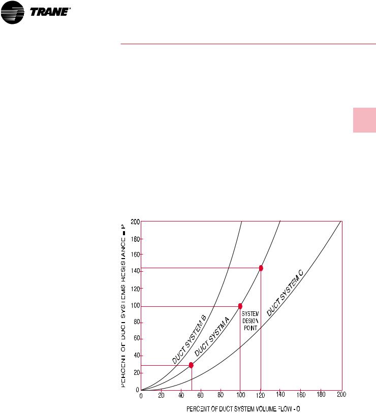
System Curve
At a fixed volume flow rate (cfm) through a given air system, a corresponding pressure loss, or resistance to this flow, will exist. If the flow rate is changed, the resulting pressure loss, or resistance to flow, will also change. The relationship governing this change for most systems is:
PRESSUREc/PRESSURE = (CFMc/CFM)2
The characteristic curve of a typical “fixed system” plots as a parabola in accordance with the above relationship.Typical plots of the resistance to flow versus volume flow rate are shown with normalized duct system curves, Figure A-1.
For a fixed system, an increase or decrease in system resistance results from an increase or decrease in the volume flow rate along the given system curve only.
Refer to Duct System A, Figure A-1. Assume a system design point at 100 percent volume and 100 percent resistance. If the volume flow rate is increased to 120 percent of design volume, the system resistance will increase to 144 percent of the design resistance in accordance with the system equation. A further increase in volume results in a corresponding increase in system pressure. A decrease in volume flow to 50 percent results in a 75 percent reduction in design resistance.
Figure A-1 — Normalized Duct System Curves
13

Application
Considerations
Performance Data Determination
The fan performance section of this catalog contains a fan performance table and fan curve for each fan size.
The performance data contained in this catalog was calculated from tests conducted in accordance with AMCA Standard 210 Laboratory Methods of Testing Fans for Rating.
The AMCA test procedure uses an open inlet and 10 wheel diameters of straight discharge ductwork to assure maximum static regain. The fan is direct driven by a dynamometer.
The fan performance tables in this catalog are based upon standard air: 0.075 lbs/ft3 (70 F, barometric pressure 29.92-inches Hg).
Fan Performance Curves
A fan performance curve is a graphical presentation of the performance of a fan. Usually it covers the entire range from free delivery (wide open cfm, no obstruction to flow) to no delivery (blocked tight, an airtight system with no air flowing).
The point of intersection of the system curve and the fan performance curve determines the point of operation and actual flow volume. If the system resistance has been accurately determined and the fan properly selected, their performance curves will intersect at the design flow rate. Refer to Figure A-2. The normalized Duct System A from Figure A-1 has been plotted with a normalized fan performance curve.
Temperature and Altitude Corrections
The fan performance values in the tables and curves of this catalog are based on standard air (.075 lbs/ft3). If the airflow requirement for a particular job is stated in terms of nonstandard air, a density correction needs to be made before selecting the fan. It is important to also note that most air friction charts for ducts, filters, coils, etc. are also based on standard air and corrections must be made to determine proper losses at other conditions.
Figure A-3 illustrates the ratio of air densities to standard air at various temperatures and elevations. A Q fan is designed for operation between -20 F and 150 F only.
Figure A-2 — Point of Operation — Interaction of the System Curve and the Fan Performance Curve
Figure A-3 — Air Density Corrections
14

Application
Considerations
The following is the procedure to use when selecting a fan for elevations and temperatures other than standard:
1
Determine the air density from Figure A-3.
2
Divide static pressure at the nonstandard condition by the air density ratio.
3
Use the actual cfm and corrected static pressure to determine rpm and bhp from the fan performance tables.
4
The rpm is correct as selected.
5
The bhp must be multiplied by the air density ratio determined in step one to get the actual operating bhp.
Option and Installation Kt Corrections
System effect losses due to less than ideal inlet or outlet configuration can be expressed in terms of velocity pressure by the following expression:
Inlet SP Loss =
Kti (Inlet Velocity )2
4005
Where Kti =
Inlet Option Kt + Inlet Installation Kt
Outlet SP Loss =
Kto (Outlet Velocity)2
4005
Where Kto = Outlet Option Kt + Outlet
Installation Kt
Kt is the loss factor for the inlet or discharge condition being considered.
It is necessary to add all of the static pressure loss determined from the above equation to the component static pressure to determine the point of duty static pressure for selection of the fan.
Fan Option Kt Corrections
The fan static pressure should be adjusted for fan options. Option pressure drops are documented as Kt losses and are handled the same way as installation Kt effects (losses). Use Table A-1, Q Fan/Super Q II Fan Kt corrections, to determine the Kt values. Add these values to any installation Kt values. Use the result to select the fan.
Table A-1 — Q Fan/Super Q II Fan Installation Kt Corrections
Unducted (Plenum) Inlet* |
|
Unducted Outlet |
|
|
|
|
Draw-Thru Type Design |
0.0 |
Blow-Thru Type Design |
+.8 |
|
|
|
Ducted Inlet |
|
Ducted Outlet |
|
|
|
|
Turn > 3 Dia Upstream |
-1.0 |
Turn > 2 Dia Downstream |
0.0 |
|
|
|
Turn |
2 Dia Upstream |
+.8 |
Turn 1 Dia Downstream |
+1.3 |
|
|
Turn |
1 Dia Upstream |
+1.3 |
Turn < 1 Dia Downstream |
|
|
|
|
|
|
||||
Turn < 1 Dia Upstream |
|
Not Recommended |
|
|
||
|
Not Recommended |
|
|
|
|
|
|
|
|
|
|
|
|
|
|
|
|
|
|
|
Figure A-4 — Ducted Turns Near Q Fan
Table A-2 — Q Fan/Super Q II Fan Option Kt Corrections
|
|
|
Super Q II |
Pressure |
Options |
Use |
Q-Fan |
Fan |
Drop (Kt) |
Inlet Flange |
Connects to bolted inlet duct |
X |
|
0 |
Inlet Bellmouth* |
Reduces Unducted Inlet Kt |
X |
X |
-.1 |
Inlet Plus Silencer |
Reduces inlet noise |
X |
X |
+.1 |
Inlet Screen |
Protects Unducted Inlets |
X |
X |
+.1 |
Outlet Screen |
Protects Unducted Outlets |
X |
|
+.5 |
Outlet Flange |
Connects to bolted outlet duct |
X |
|
0 |
Outlet Equalizer (Diffuser) |
Improves SE |
X |
|
0 |
Outlet Plus Silencer |
Reduces Outlet Noise |
X |
X |
+.1 |
Outlet Flow Stabilization Screen |
Reduces Outlet swirl |
X |
X |
+.8 |
Outlet Backdraft Damper |
Isolates fan from duct |
Special |
Special |
+.5 |
Frequency Drive Modulation |
Modulates Q Fan quietly |
Special |
Special |
0 |
Belt Guard |
Protects drives/belts |
X |
|
0 |
Motor Rails |
Allows motor to be mounted |
X |
Included |
0 |
Standard Isolators |
Isolates fan |
X |
Included |
0 |
Seismic Isolators |
Isolates fan |
X |
Special |
0 |
*Note: Bellmouth effect included in unducted installation Kt correction. Fan sizes 49 through 60 fan curves are cataloged with inlet bells. For unducted inlets without bells on size 49 through 60 fans add .1 to the inlet Kt given above.
Inlet vane losses are covered in the Selection Procedure with air density corrections (page 20).
15
Application
Considerations
Q and Super Q II Fan Modulation — AC Inverter Capacity Control
Q fans and Super Q II fans can be modulated with AC frequency drives. TheTrane Company recommends Magnetek low noise inverter drives and Century high efficiency motors for optimum modulation performance.
Operating the Q or Super Q II fan on AC frequency drives requires the Q fan to be strengthened and balanced in the factory.This option “beefs up” the mechanical bracing of the Q fan inlet bearing assembly and calls for a precision factory balance. Precision balancing covers 10 operating points on the system curve from 10 percent load to full load.
Minimum cfm with AC inverters — Above 1.5” static pressure, the minimum cfm is the surge (do not select) line. Below 1.5” static pressure, it is 1000 cfm.
Q Fan Modulation — InletVanes
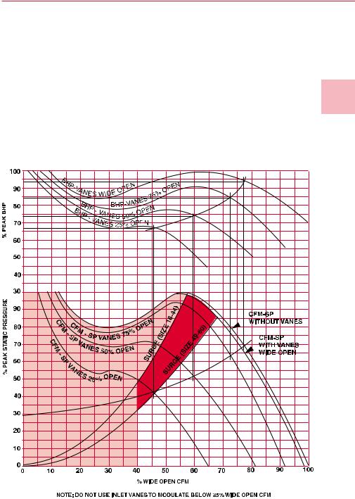
Inlet vanes are a widely used form of fan modulation. As inlet vanes close, they impart a spin on the incoming air in the direction of the fan wheel rotation.This reduces airflow, static pressure and brake horsepower. However, inlet vanes do increase sound levels. If a job is acoustically sensitive, AC inverters are recommended for modulation. As shown in Figure A-5, a separate cfm static pressure curve (cfm-sp) is generated per each inlet vane position. Likewise, the figure shows brake horsepower curves that apply for various inlet vane positions.
Inlet vanes are controlled by placing a static pressure sensor in the downstream ductwork, typically about two-thirds of the way down the longest trunk duct. This sensor is set at a static pressure that will ensure sufficient pressure is available to move air from that point through the remaining duct work. The sensor will respond to duct pressure changes and signal the inlet vane operator to open or close the vanes to maintain the control setting at the sensor location.
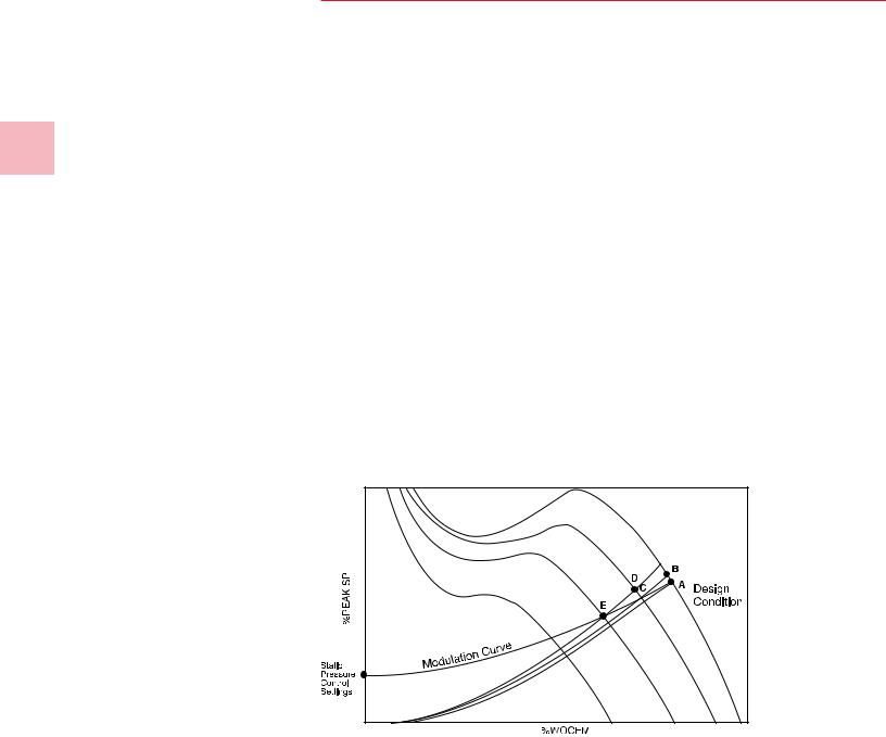
AsVAV terminal units begin to close in response to a decreasing cooling load, static pressure in the ductwork increases. This causes the fan operating point to temporarily move upward to the left on a constant rpm curve as shown in Figure A-5 (point A to point B). The static pressure sensor will detect an increase in duct pressure and signal the inlet vane operator to begin to close the vanes. The inlet vanes will close until the static pressure sensor is again satisfied, moving the operation point to C (Figure A-5). As the cooling load continues to decrease, the modulation curve will be formed (point C to D, and point D to E) on Figure A-5. This curve passes through the design point and through the static pressure sensor control point. The static pressure of any point on this curve can be calculated using the formula:
Sp = (Cfm/Cfmd)2 x (SPd-SPc) = SPc
SPd = static pressure at design,
SPc = static pressure control setting, Cfmd = cfm at design.
Figure A-5 – VAV System Modulation Curve
TheVAV system modulation curve can be drawn using aTrane system modulation overlay.The axis of the overlay is placed on a static pressure control setting. The curve that intersects the design points is the system modulation curve.
Because the axes of the inlet vane performance graph are in terms of percent wide open cfm (wocfm) and percent peak static pressure, the first step in establishing the system modulation curve is to find the proper design points. By plotting the design point on the performance
curve for the fan in question, one can easily determine the percent wocfm. Knowing this, plot a point on the cfm-sp curve (Figure A-6) for inlet vanes wide open, at the design point of wocfm. By tracing to the left, one can determine the percent of peak static pressure. By knowing the design cfm, static pressure and the percent of wide open cfm and percent peak static that these values represent, one can calculate wocfm and peak static pressure.
16
Application
Considerations
The control static pressure can then be expressed as a percent of peak static pressure and plotted. The system modulation curve is described by the curve on the modulation overlay that passes through the design point when the axis is placed on the control static pressure point.
The minimum inlet vane cfm can easily be determined after the system modulation has been established. It will be one of two things, either a) the point where the system modulation curve intersects the surge line, or
b) 40 percent wocfm, whichever is greater. Forty percent wocfm is the minimum point a Q fan with inlet vanes can modulate, due to inherent instability that results when the vanes close to a certain angle.
A plot of part load cfm versus brake horsepower can also be made after the system modulation curve is established. At each intersection of the system modulation curve with a cfm-sp curve for a certain inlet vane opening, a vertical line is traced to the appropriate bhp-cfm curve. At each intersection of a bhp-cfm curve, a horizontal line is traced to the scale of percent brake horsepower.This will lead to a percent wocfm versus percent peak bhp plot.
The design rpm and bhp need to be corrected to account for performance losses due to inlet vanes being in the air stream. A correction of one percent to the rpm and three percent to the bhp is made in order to get to design conditions with the inlet vanes fully open.
Part load fan power consumption with inlet vanes can be determined by entering Figure A-6 at the desired percent wide open cfm. (Wide open cfm is found on the fan curve by following the fan rpm to the right until it intersects the 0” static pressure axis.)
Figure A-6 – Inlet Vane Performance
On Figure A-6, plot a system curve from the control static pressure through the point of operation defined as a calculated percent wide open cfm. Read vertically upward from the 25, 50 and 75 percent intersections to determine the percent bhp at part load.
Intermediate operating points are found by extrapolation. Inlet vanes increase Q fan sound levels. SeeTable A-5.
17
 Loading...