


 Loading...
HP ENVY 15
Maintenance and Service Guide
Document Part Number: 577090-001
September 2009
This guide is a troubleshooting reference used for maintaining and servicing the computer. It provides comprehensive information on identifying computer features, components, and spare parts; troubleshooting computer problems; and performing computer disassembly procedures.
© Copyright 2009 Hewlett-Packard Development Company, L.P.
ATI and ATI Mobility Radeon are trademarks of Advanced Micro Devices, Inc. Bluetooth is a trademark owned by its proprietor and used by Hewlett-Packard Company under license. Intel and Core are trademarks of Intel Corporation in the U.S. and other countries. Microsoft and Windows are U.S. registered trademarks of Microsoft Corporation. SD Logo is a trademark of its proprietor.
The information contained herein is subject to change without notice. The only warranties for HP products and services are set forth in the express warranty statements accompanying such products and services. Nothing herein should be construed as constituting an additional warranty. HP shall not be liable for technical or editorial errors or omissions contained herein.
First Edition: September 2009
Document Part Number: 577090-001

Safety warning notice
ÅWARNING: To reduce the possibility of heat-related injuries or of overheating the computer, do not place the computer directly on your lap or obstruct the computer air vents. Use the computer only on a hard, flat surface. Do not allow another hard surface, such as an adjoining optional printer, or a soft surface, such as pillows or rugs or clothing, to block airflow. Also, do not allow the AC adapter to contact the skin or a soft surface, such as pillows or rugs or clothing, during operation. The computer and the AC adapter comply with the user-accessible surface temperature limits defined by the International Standard for Safety of Information Technology Equipment (IEC 60950).

Contents
1Product description
2External component identification
Identifying hardware . . . . . . . . . . . . . . . . . . . . . . . . . . . . . . . . . . . . . . . . . . . . . . . . . . . . . . . . . . . . . . . . . . 2–1 Top components. . . . . . . . . . . . . . . . . . . . . . . . . . . . . . . . . . . . . . . . . . . . . . . . . . . . . . . . . . . . . . . . . . . . . . 2–2 Display components . . . . . . . . . . . . . . . . . . . . . . . . . . . . . . . . . . . . . . . . . . . . . . . . . . . . . . . . . . . . . . . 2–2 Button . . . . . . . . . . . . . . . . . . . . . . . . . . . . . . . . . . . . . . . . . . . . . . . . . . . . . . . . . . . . . . . . . . . . . . . . . . 2–3 Keys . . . . . . . . . . . . . . . . . . . . . . . . . . . . . . . . . . . . . . . . . . . . . . . . . . . . . . . . . . . . . . . . . . . . . . . . . . . 2–4 Lights . . . . . . . . . . . . . . . . . . . . . . . . . . . . . . . . . . . . . . . . . . . . . . . . . . . . . . . . . . . . . . . . . . . . . . . . . . 2–5 TouchPad . . . . . . . . . . . . . . . . . . . . . . . . . . . . . . . . . . . . . . . . . . . . . . . . . . . . . . . . . . . . . . . . . . . . . . . 2–6 TouchPad buttons . . . . . . . . . . . . . . . . . . . . . . . . . . . . . . . . . . . . . . . . . . . . . . . . . . . . . . . . . . . . . . . . . 2–7 Front components. . . . . . . . . . . . . . . . . . . . . . . . . . . . . . . . . . . . . . . . . . . . . . . . . . . . . . . . . . . . . . . . . . . . . 2–8 Left-side components . . . . . . . . . . . . . . . . . . . . . . . . . . . . . . . . . . . . . . . . . . . . . . . . . . . . . . . . . . . . . . . . . . 2–8 Right-side components. . . . . . . . . . . . . . . . . . . . . . . . . . . . . . . . . . . . . . . . . . . . . . . . . . . . . . . . . . . . . . . . . 2–9 Bottom components . . . . . . . . . . . . . . . . . . . . . . . . . . . . . . . . . . . . . . . . . . . . . . . . . . . . . . . . . . . . . . . . . . 2–10
3 Illustrated parts catalog
Service tag . . . . . . . . . . . . . . . . . . . . . . . . . . . . . . . . . . . . . . . . . . . . . . . . . . . . . . . . . . . . . . . . . . . . . . . . . . 3–1 Computer major components . . . . . . . . . . . . . . . . . . . . . . . . . . . . . . . . . . . . . . . . . . . . . . . . . . . . . . . . . . . . 3–3 Display components. . . . . . . . . . . . . . . . . . . . . . . . . . . . . . . . . . . . . . . . . . . . . . . . . . . . . . . . . . . . . . . . . . . 3–9 Mass storage devices . . . . . . . . . . . . . . . . . . . . . . . . . . . . . . . . . . . . . . . . . . . . . . . . . . . . . . . . . . . . . . . . . 3–11 Miscellaneous parts . . . . . . . . . . . . . . . . . . . . . . . . . . . . . . . . . . . . . . . . . . . . . . . . . . . . . . . . . . . . . . . . . . 3–13 Sequential part number listing . . . . . . . . . . . . . . . . . . . . . . . . . . . . . . . . . . . . . . . . . . . . . . . . . . . . . . . . . . 3–14
4 Removal and replacement procedures
Preliminary replacement requirements . . . . . . . . . . . . . . . . . . . . . . . . . . . . . . . . . . . . . . . . . . . . . . . . . . . . 4–1 Tools required . . . . . . . . . . . . . . . . . . . . . . . . . . . . . . . . . . . . . . . . . . . . . . . . . . . . . . . . . . . . . . . . . . . . 4–1 Service considerations. . . . . . . . . . . . . . . . . . . . . . . . . . . . . . . . . . . . . . . . . . . . . . . . . . . . . . . . . . . . . . 4–1 Grounding guidelines . . . . . . . . . . . . . . . . . . . . . . . . . . . . . . . . . . . . . . . . . . . . . . . . . . . . . . . . . . . . . . 4–2 Service tag . . . . . . . . . . . . . . . . . . . . . . . . . . . . . . . . . . . . . . . . . . . . . . . . . . . . . . . . . . . . . . . . . . . . . . . . . . 4–5 Component replacement procedures . . . . . . . . . . . . . . . . . . . . . . . . . . . . . . . . . . . . . . . . . . . . . . . . . . . . . . 4–6 Computer feet . . . . . . . . . . . . . . . . . . . . . . . . . . . . . . . . . . . . . . . . . . . . . . . . . . . . . . . . . . . . . . . . . . . . 4–6 Battery. . . . . . . . . . . . . . . . . . . . . . . . . . . . . . . . . . . . . . . . . . . . . . . . . . . . . . . . . . . . . . . . . . . . . . . . . . 4–7 Expansion memory module . . . . . . . . . . . . . . . . . . . . . . . . . . . . . . . . . . . . . . . . . . . . . . . . . . . . . . . . . 4–8 Top cover . . . . . . . . . . . . . . . . . . . . . . . . . . . . . . . . . . . . . . . . . . . . . . . . . . . . . . . . . . . . . . . . . . . . . . 4–10 Keyboard. . . . . . . . . . . . . . . . . . . . . . . . . . . . . . . . . . . . . . . . . . . . . . . . . . . . . . . . . . . . . . . . . . . . . . . 4–12 Speaker assembly . . . . . . . . . . . . . . . . . . . . . . . . . . . . . . . . . . . . . . . . . . . . . . . . . . . . . . . . . . . . . . . . 4–14 Primary memory module . . . . . . . . . . . . . . . . . . . . . . . . . . . . . . . . . . . . . . . . . . . . . . . . . . . . . . . . . . 4–15 WLAN module . . . . . . . . . . . . . . . . . . . . . . . . . . . . . . . . . . . . . . . . . . . . . . . . . . . . . . . . . . . . . . . . . . 4–16 RTC battery. . . . . . . . . . . . . . . . . . . . . . . . . . . . . . . . . . . . . . . . . . . . . . . . . . . . . . . . . . . . . . . . . . . . . 4–19 Hard drive . . . . . . . . . . . . . . . . . . . . . . . . . . . . . . . . . . . . . . . . . . . . . . . . . . . . . . . . . . . . . . . . . . . . . . 4–20
Maintenance and Service Guide |
iv |

Contents
Processor fan/heat sink assembly . . . . . . . . . . . . . . . . . . . . . . . . . . . . . . . . . . . . . . . . . . . . . . . . . . . . 4–22 Processor . . . . . . . . . . . . . . . . . . . . . . . . . . . . . . . . . . . . . . . . . . . . . . . . . . . . . . . . . . . . . . . . . . . . . . . 4–24 Power button board and cable. . . . . . . . . . . . . . . . . . . . . . . . . . . . . . . . . . . . . . . . . . . . . . . . . . . . . . . 4–25 Power connector cable . . . . . . . . . . . . . . . . . . . . . . . . . . . . . . . . . . . . . . . . . . . . . . . . . . . . . . . . . . . . 4–26 Video fan/heat sink assembly . . . . . . . . . . . . . . . . . . . . . . . . . . . . . . . . . . . . . . . . . . . . . . . . . . . . . . . 4–27 System board. . . . . . . . . . . . . . . . . . . . . . . . . . . . . . . . . . . . . . . . . . . . . . . . . . . . . . . . . . . . . . . . . . . . 4–29 Display assembly . . . . . . . . . . . . . . . . . . . . . . . . . . . . . . . . . . . . . . . . . . . . . . . . . . . . . . . . . . . . . . . . 4–33
5 Setup Utility (BIOS)
Starting Setup Utility . . . . . . . . . . . . . . . . . . . . . . . . . . . . . . . . . . . . . . . . . . . . . . . . . . . . . . . . . . . . . . . . . . 5–1 Using Setup Utility. . . . . . . . . . . . . . . . . . . . . . . . . . . . . . . . . . . . . . . . . . . . . . . . . . . . . . . . . . . . . . . . . . . . 5–1 Changing the language of Setup Utility . . . . . . . . . . . . . . . . . . . . . . . . . . . . . . . . . . . . . . . . . . . . . . . . 5–1 Navigating and selecting in Setup Utility . . . . . . . . . . . . . . . . . . . . . . . . . . . . . . . . . . . . . . . . . . . . . . . 5–2 Displaying system information . . . . . . . . . . . . . . . . . . . . . . . . . . . . . . . . . . . . . . . . . . . . . . . . . . . . . . . 5–2 Restoring default settings in Setup Utility . . . . . . . . . . . . . . . . . . . . . . . . . . . . . . . . . . . . . . . . . . . . . . 5–2 Exiting Setup Utility . . . . . . . . . . . . . . . . . . . . . . . . . . . . . . . . . . . . . . . . . . . . . . . . . . . . . . . . . . . . . . . 5–3 Setup Utility menus . . . . . . . . . . . . . . . . . . . . . . . . . . . . . . . . . . . . . . . . . . . . . . . . . . . . . . . . . . . . . . . . . . . 5–3 Main menu . . . . . . . . . . . . . . . . . . . . . . . . . . . . . . . . . . . . . . . . . . . . . . . . . . . . . . . . . . . . . . . . . . . . . . 5–3 Security menu . . . . . . . . . . . . . . . . . . . . . . . . . . . . . . . . . . . . . . . . . . . . . . . . . . . . . . . . . . . . . . . . . . . . 5–3 System Configuration menu . . . . . . . . . . . . . . . . . . . . . . . . . . . . . . . . . . . . . . . . . . . . . . . . . . . . . . . . . 5–4 Diagnostics menu . . . . . . . . . . . . . . . . . . . . . . . . . . . . . . . . . . . . . . . . . . . . . . . . . . . . . . . . . . . . . . . . . 5–4 Updating the BIOS. . . . . . . . . . . . . . . . . . . . . . . . . . . . . . . . . . . . . . . . . . . . . . . . . . . . . . . . . . . . . . . . . . . . 5–5 Updating the BIOS . . . . . . . . . . . . . . . . . . . . . . . . . . . . . . . . . . . . . . . . . . . . . . . . . . . . . . . . . . . . . . . . 5–5
6 Specifications
Computer specifications. . . . . . . . . . . . . . . . . . . . . . . . . . . . . . . . . . . . . . . . . . . . . . . . . . . . . . . . . . . . . . . . 6–1 15.6-in display specifications. . . . . . . . . . . . . . . . . . . . . . . . . . . . . . . . . . . . . . . . . . . . . . . . . . . . . . . . . . . . 6–2 Hard drive specifications . . . . . . . . . . . . . . . . . . . . . . . . . . . . . . . . . . . . . . . . . . . . . . . . . . . . . . . . . . . . . . . 6–3 9.5-mm, 2.5-in hard drive . . . . . . . . . . . . . . . . . . . . . . . . . . . . . . . . . . . . . . . . . . . . . . . . . . . . . . . . . . . 6–3 8.0-mm, 1.8-in hard drive . . . . . . . . . . . . . . . . . . . . . . . . . . . . . . . . . . . . . . . . . . . . . . . . . . . . . . . . . . . 6–4 Blu-ray ROM DVD±R/RW SuperMulti Double-Layer Drive specifications . . . . . . . . . . . . . . . . . . . . . . . 6–5 DVD±RW and CD-RW SuperMulti Double-Layer Combo Drive specifications. . . . . . . . . . . . . . . . . . . . 6–6 System DMA specifications. . . . . . . . . . . . . . . . . . . . . . . . . . . . . . . . . . . . . . . . . . . . . . . . . . . . . . . . . . . . . 6–7 System memory map specifications. . . . . . . . . . . . . . . . . . . . . . . . . . . . . . . . . . . . . . . . . . . . . . . . . . . . . . . 6–7 System interrupt specifications . . . . . . . . . . . . . . . . . . . . . . . . . . . . . . . . . . . . . . . . . . . . . . . . . . . . . . . . . . 6–8 System I/O address specifications . . . . . . . . . . . . . . . . . . . . . . . . . . . . . . . . . . . . . . . . . . . . . . . . . . . . . . . . 6–9
7 Screw listing
Phillips PM2.0×4.0 screw . . . . . . . . . . . . . . . . . . . . . . . . . . . . . . . . . . . . . . . . . . . . . . . . . . . . . . . . . . . . . . 7–1 Phillips PM2.0×12.0 screw . . . . . . . . . . . . . . . . . . . . . . . . . . . . . . . . . . . . . . . . . . . . . . . . . . . . . . . . . . . . . 7–3 Phillips PM2.0×5.0 screw . . . . . . . . . . . . . . . . . . . . . . . . . . . . . . . . . . . . . . . . . . . . . . . . . . . . . . . . . . . . . . 7–4 Phillips PM2.0×2.0 screw . . . . . . . . . . . . . . . . . . . . . . . . . . . . . . . . . . . . . . . . . . . . . . . . . . . . . . . . . . . . . . 7–5 Phillips PM1.5×1.5 screw . . . . . . . . . . . . . . . . . . . . . . . . . . . . . . . . . . . . . . . . . . . . . . . . . . . . . . . . . . . . . . 7–6 Phillips PM2.0×4.0 broadhead screw . . . . . . . . . . . . . . . . . . . . . . . . . . . . . . . . . . . . . . . . . . . . . . . . . . . . . 7–7 Phillips PM3.0×4.0 screw . . . . . . . . . . . . . . . . . . . . . . . . . . . . . . . . . . . . . . . . . . . . . . . . . . . . . . . . . . . . . . 7–8 Phillips PM2.0×6.0 captive screw . . . . . . . . . . . . . . . . . . . . . . . . . . . . . . . . . . . . . . . . . . . . . . . . . . . . . . . . 7–9 Phillips PM2.0×3.0 screw . . . . . . . . . . . . . . . . . . . . . . . . . . . . . . . . . . . . . . . . . . . . . . . . . . . . . . . . . . . . . 7–10 Phillips PM2.5×6.0 screw . . . . . . . . . . . . . . . . . . . . . . . . . . . . . . . . . . . . . . . . . . . . . . . . . . . . . . . . . . . . . 7–13
v |
Maintenance and Service Guide |

Contents
8 Backup and recovery
Creating recovery discs . . . . . . . . . . . . . . . . . . . . . . . . . . . . . . . . . . . . . . . . . . . . . . . . . . . . . . . . . . . . . . . . 8–2 Backing up your information . . . . . . . . . . . . . . . . . . . . . . . . . . . . . . . . . . . . . . . . . . . . . . . . . . . . . . . . . . . . 8–3 Using Windows Backup and Restore . . . . . . . . . . . . . . . . . . . . . . . . . . . . . . . . . . . . . . . . . . . . . . . . . . 8–4 Using system restore points . . . . . . . . . . . . . . . . . . . . . . . . . . . . . . . . . . . . . . . . . . . . . . . . . . . . . . . . . 8–4 Performing a recovery . . . . . . . . . . . . . . . . . . . . . . . . . . . . . . . . . . . . . . . . . . . . . . . . . . . . . . . . . . . . . . . . . 8–5 Recovering from the recovery discs . . . . . . . . . . . . . . . . . . . . . . . . . . . . . . . . . . . . . . . . . . . . . . . . . . . 8–6
9 Connector pin assignments
Audio-in (microphone). . . . . . . . . . . . . . . . . . . . . . . . . . . . . . . . . . . . . . . . . . . . . . . . . . . . . . . . . . . . . . . . . 9–1
Audio-out (headphone) . . . . . . . . . . . . . . . . . . . . . . . . . . . . . . . . . . . . . . . . . . . . . . . . . . . . . . . . . . . . . . . . 9–1
HDMI . . . . . . . . . . . . . . . . . . . . . . . . . . . . . . . . . . . . . . . . . . . . . . . . . . . . . . . . . . . . . . . . . . . . . . . . . . . . . . 9–2
RJ-45 (network) . . . . . . . . . . . . . . . . . . . . . . . . . . . . . . . . . . . . . . . . . . . . . . . . . . . . . . . . . . . . . . . . . . . . . . 9–3
Universal Serial Bus. . . . . . . . . . . . . . . . . . . . . . . . . . . . . . . . . . . . . . . . . . . . . . . . . . . . . . . . . . . . . . . . . . . 9–4
10Power cord set requirements
Requirements for all countries and regions . . . . . . . . . . . . . . . . . . . . . . . . . . . . . . . . . . . . . . . . . . . . . . . . 10–1 Requirements for specific countries and regions . . . . . . . . . . . . . . . . . . . . . . . . . . . . . . . . . . . . . . . . . . . . 10–2
11Recycling
Battery . . . . . . . . . . . . . . . . . . . . . . . . . . . . . . . . . . . . . . . . . . . . . . . . . . . . . . . . . . . . . . . . . . . . . . . . . . . . 11–1
Display . . . . . . . . . . . . . . . . . . . . . . . . . . . . . . . . . . . . . . . . . . . . . . . . . . . . . . . . . . . . . . . . . . . . . . . . . . . . 11–1
Index
Maintenance and Service Guide |
vi |

1
Product description
Category |
Description |
|
|
Product name |
HP ENVY 15 Notebook PC |
|
|
Processors |
Intel® Core™ i7-820QM 1.73-GHz processor with embedded |
|
Northbridge (SC turbo up to 3.06-GHz) |
|
Intel Core i7-720QM 1.60-GHz processor with embedded Northbridge |
|
(SC turbo up to 2.80-GHz) |
|
|
Chipset |
Intel 5 series express chipsets |
|
PM57 platform controller hub (PCH) Peak-M |
|
|
Graphics |
ATI Mobility Radeon™ HD 4830 (M97) Discrete PCI Express Graphics |
|
with 1 GB of dedicated video memory (64M×16, 1.5V, 800 MHz, DDR3 |
|
@1333 MHz) |
|
|
Panel |
15.6-in AntiGlare, full high-definition (FHD) (1920 × 1080), |
|
light-emitting diode (LED), dual-channel display assembly |
|
15.6-in BrightView, HD (1368 × 768), LED display assembly |
|
16 × 9 wide aspect ratio |
|
Supports privacy filter |
|
Includes 2 wireless local-area network (WLAN) antennas |
|
Supports ambient light sensor (ALS) |
|
|
Memory |
4 memory module slots (customer accessible/upgradeable), supports |
|
up to 16-GB memory |
|
Supports DDR3, 1066-MHz dual channel memory |
|
|
|
(Continued) |
Maintenance and Service Guide |
1–1 |

Product description
Category |
Description |
|
|
Mass storage devices |
Supports either 8.0-mm SATA 1.8-in or 9.5-mm SATA 2.5-in hard drives |
|
Supports the following hard drive configurations: |
|
2.5-in, 7200-rpm: |
|
■ 640-GB |
|
■ 500-GB |
|
■ 320-GB |
|
■ 250-GB |
|
1.8-in, 5400-rpm: |
|
■ 320-GB |
|
■ 250-GB |
|
■ 160-GB |
|
|
Optical drive |
External USB support for the following: |
|
■ Blu-ray ROM with LightScribe DVD±R/RW SuperMulti |
|
Double-Layer Drive |
|
■ DVD±RW and CD-RW SuperMulti Double-Layer Combo Drive |
|
with LightScribe |
|
|
Microphone |
2 integrated digital dual-array microphones |
|
Microphone jack |
|
|
Webcam |
Night-vision/low-light VGA camera with infrared LED for illumination |
|
Supports OVT7738 camera sensor with F2.0, dual-band lens |
|
Fixed (no tilt) |
|
Activity light |
|
640 × 480 by 24 frames per second |
|
|
Audio |
HD IDT 92HD75B audio |
|
Dolby Home Theater technology |
|
2 stereo speakers with 2-watt power rating |
|
Headphone jack |
|
|
Ethernet |
Marvell 88E8072-B1 10/100/1000 Ethernet |
|
S3/S5 wake on LAN (AC mode only) |
|
Ethernet cable not included |
|
|
|
(Continued) |
1–2 |
Maintenance and Service Guide |

Product description
Category |
Description |
|
|
Power requirements |
120and 90-W HP Smart Adapter (100–240V) |
|
Battery options: |
|
■ Primary battery: 6-cell, 2.40-Ah (53-Wh) Li-ion battery, |
|
user replaceable |
|
■ Extended battery: 9-cell, 2.80-Ah (93-Wh) Li-ion battery, |
|
user replaceable |
|
|
Wireless |
Integrated WLAN options by way of wireless module |
|
2 wireless antennas built into display assembly |
|
Supports no-WLAN option |
|
Support for the following WLAN formats: |
|
■ Intel WiFi Link 6200 802.11 a/g/n |
|
■ Intel WiFi Link 6200 802.11 a/g/n with Bluetooth® |
|
■ Intel WiFi Link 5100 802.11 a/g/n |
|
■ Intel WiFi Link 5100 802.11 a/g/n with Bluetooth |
|
■ Intel WiFi Link 6100 802.11 a/b/g |
|
■ Intel WiFi Link 6100 802.11 a/b/g with Bluetooth |
|
■ Intel WiFi Link 5100 802.11 a/b/g |
|
■ Intel WiFi Link 5100 802.11 a/b/g with Bluetooth |
|
■ Intel 1000 802.11 b/g/n |
|
■ Intel 1000 802.11 b/g/n with Bluetooth |
|
■ Intel 1000 802.11 b/g |
|
■ Intel 1000 802.11 b/g with Bluetooth |
|
|
External media cards |
Digital Media Slot |
|
Supports the following digital card formats: |
|
■ MultiMediaCard |
|
■ micro MultiMediaCard (adapter required) |
|
■ MultiMediaCard Plus |
|
■ Secure Digital (SD) Memory Card |
|
■ micro Secure Digital Memory Card (adapter required) |
|
■ Secure Digital High Capacity Memory Card |
|
|
|
(Continued) |
Maintenance and Service Guide |
1–3 |

Product description
Category |
Description |
|
|
Ports |
3.5-mm headphone/microphone combo jack (stereo, supports jack |
|
detection) |
|
eSATA/USB 2.0 combo port (1) |
|
High Definition Multimedia Interface (HDMI) v1.3b supporting |
|
1920 × 1080 at 60 Hz |
|
HP Smart Adapter AC adapter plug |
|
RJ-45 |
|
Primary battery connector |
|
Secondary battery connector |
|
USB 3.0 ports (2, each capable of driving an external optical drive) |
|
USB 2.0 ports (2, each capable of driving an external optical drive) |
|
The total combined power for all USB ports is 3.0 amps, with all |
|
power available from any single port. This power is available |
|
whenever the AC adapter is supplying power, including S3 and |
|
S5 modes. |
|
|
Keyboard/ |
Full-size optimized keyboard with 1.8-mm keystroke travel distance |
pointing devices |
TouchPad with gesture support (media “M,” scroll, pinch, zoom) |
|
Taps enabled by default |
|
|
Serviceability |
End-user replaceable parts: |
|
AC adapter |
|
Battery |
|
External optical drive |
|
Memory (only 2 slots are customer accessible) |
|
|
Security |
Security cable slot with adapter |
|
|
Operating system |
Preinstalled: |
|
■ Microsoft® Windows® 7 Home Premium 64 |
|
■ Microsoft Windows 7 Professional 64 |
|
■ Configurable Linux embedded |
|
|
1–4 |
Maintenance and Service Guide |
2
External component identification
Identifying hardware
Components included with the computer may vary by region and model. The illustrations in this chapter identify the standard features on most computer models.
To see a list of hardware installed in the computer:
» Select Start > Control Panel > System and Security. Then in the System area, click Device Manager.
You can also add hardware or modify device configurations using Device Manager.
Windows includes the User Account Control feature to improve the security of your computer. You may be prompted for your permission or password for tasks such as installing software, running utilities, or changing Windows settings. Refer to Help and Support for more information.
Maintenance and Service Guide |
2–1 |
External component identification
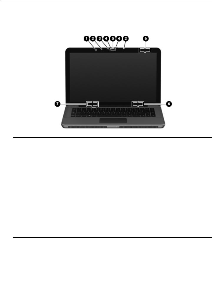
Top components
Display components
Item |
Component |
Description |
|
|
|
(1) |
Ambient light sensor |
Adjusts the screen brightness levels automatically, based on surrounding |
|
|
lighting conditions. |
|
|
|
(2) |
Internal microphones (2) |
Record sound. |
|
|
|
(3) |
Webcam light |
On: The webcam is in use. |
|
|
|
(4) |
Webcam infrared (IR) lights (2) |
Improve the webcam picture quality in low-light conditions. |
|
|
|
(5) |
Webcam |
Records video and captures still photographs. |
|
|
|
(6) |
Wireless antennas (2) |
Send and receive signals from one or more wireless devices. These antennas |
|
|
are not visible from the outside of the computer. |
|
|
For optimal transmission, keep the areas immediately around the |
|
|
antennas free from obstructions. |
|
|
To see wireless regulatory notices, refer to the section of the Regulatory, |
|
|
Safety and Environmental Notices that applies to your country or region. |
|
|
These notices are located in Help and Support. |
|
|
|
(7) |
Internal display switch |
Turns off the display and initiates Sleep if the display is closed while the power |
|
|
is on. |
Thecomputer.internal display switch is not visible from the outside of the
2–2 |
Maintenance and Service Guide |
External component identification
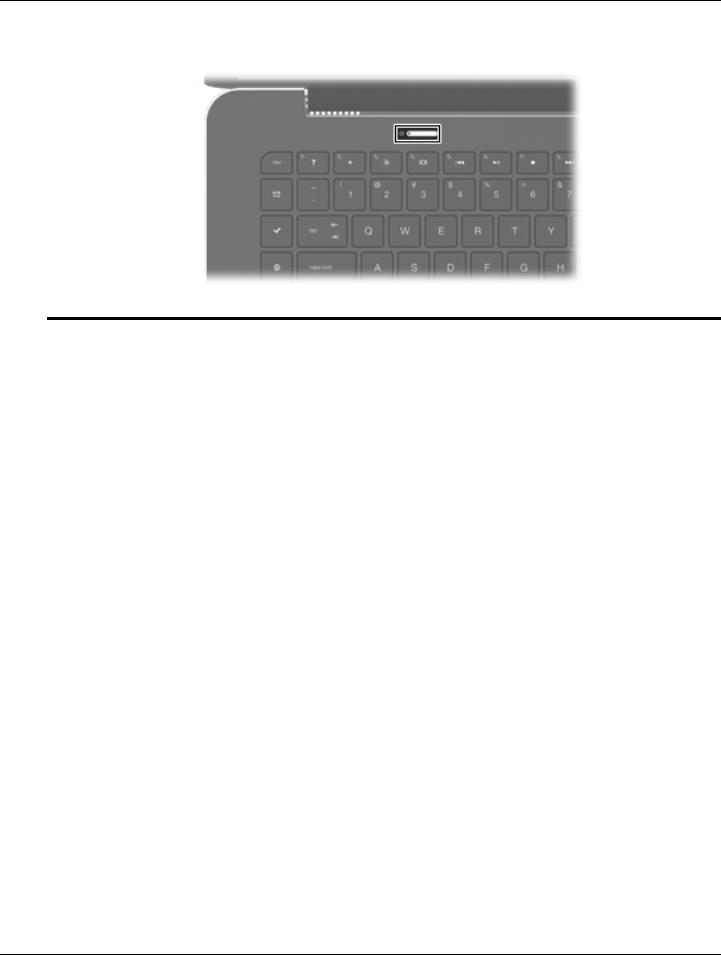
Button
Component |
Description |
|
|
Power button |
■ When the computer is off, press the button to turn on the computer. |
|
■ When the computer is on, press the button briefly to initiate Sleep. |
|
■ When the computer is in the Sleep state, press the button briefly to |
|
exit Sleep. |
|
■ When the computer is in Hibernation, press the button briefly to |
|
exit Hibernation. |
|
If the computer has stopped responding and Windows shutdown procedures |
|
are ineffective, press and hold the power button for at least 5 seconds to turn |
|
off the computer. |
|
To learn more about your power settings, select Start > Control Panel > |
|
System and Security > Power Options. |
|
|
Maintenance and Service Guide |
2–3 |
External component identification
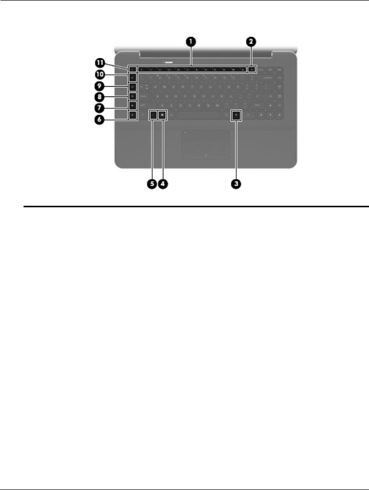
Keys
Item |
Component |
Description |
|
|
|
(1) |
Action keys |
Execute frequently used system functions. |
|
|
|
(2) |
wireless key |
Turns the wireless feature on or off. |
|
|
This key does not establish a wireless connection. To establish a |
|
|
wireless connection, a wireless network must also be set up. |
|
|
|
(3) |
Windows applications key |
Displays a shortcut menu for items beneath the cursor. |
|
|
|
(4) |
Windows logo key |
Displays the Windows Start menu. |
|
|
|
(5) |
fn key |
Executes frequently used system functions when pressed in combination with |
|
|
a function key or the esc key. |
|
|
|
(6) |
calculator key |
Opens the Windows calculator function. |
|
|
|
(7) |
print options key |
Opens the Print Options window of the active Windows program. |
|
|
|
(8) |
Web key |
Opens a Web browser. |
|
|
Until you have set up your Internet or network services, the Web key |
|
|
opens the Windows Internet Connection Wizard. After you have set up |
|
|
your Internet or network services and your Web browser home page, |
|
|
you can press the Web key to quickly access your home page and |
|
|
the Internet. |
|
|
|
(9) |
Media Launch key |
Opens HP MediaSmart. HP MediaSmart turns your computer into a mobile |
|
|
entertainment center. You can enjoy music and movies and manage and edit |
|
|
your photo collections. |
|
|
|
(10) |
mail key |
Opens your default e-mail program. |
|
|
The first time you press the mail key, you may be prompted to set up |
|
|
your e-mail account. After you have set up your e-mail, you can press |
|
|
the mail key to quickly access your e-mail. |
|
|
|
(11) |
esc key |
Displays system information when pressed in combination with the fn key. |
|
|
|
2–4 |
Maintenance and Service Guide |

External component identification
Lights
Item |
Component |
Description |
|
|
|
(1) |
TouchPad light |
■ Amber: The TouchPad is off. |
|
|
■ Off: The TouchPad is on. |
|
|
|
(2) |
Caps lock light |
White: Caps lock is on. |
|
|
|
(3) |
Power light |
■ White: The computer is on. |
|
|
■ Blinking white: The computer is in the Sleep state. |
|
|
■ Off: The computer is off or in Hibernation. |
|
|
|
(4) |
Mute light |
Amber: Computer sound is off. |
|
|
|
(5) |
Wireless light |
■ Off: An integrated wireless device, such as a WLAN device and/or a |
|
|
Bluetooth device, is on. |
Wireless devices are enabled at the factory.
■ Amber: All wireless devices are off.
Maintenance and Service Guide |
2–5 |
External component identification
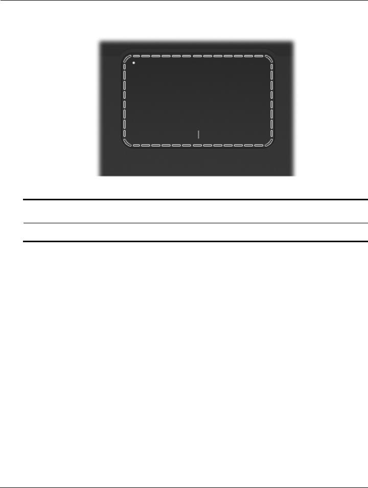
TouchPad
Component |
Description |
|
|
TouchPad* |
Moves the pointer and selects or activates items on the screen. |
*This table describes factory settings. To view and change pointing device preferences, select Start > Devices and Printers. Then, right-click the device representing your computer, and select Mouse settings.
2–6 |
Maintenance and Service Guide |
External component identification
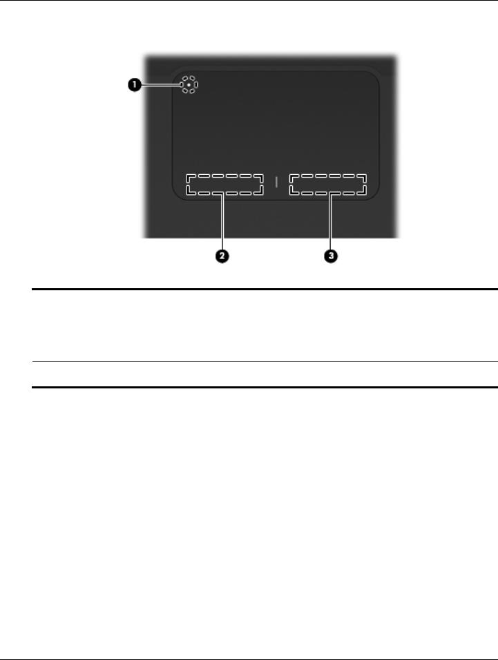
TouchPad buttons
Item |
Component |
Description |
|
|
|
(1) |
TouchPad on/off button |
Turns the TouchPad on and off. Lightly press the button and hold for |
|
|
2 seconds to turn the TouchPad on and off. |
|
|
|
(2) |
Left TouchPad button* |
Functions like the left button on an external mouse. |
|
|
|
(3) |
Right TouchPad button* |
Functions like the right button on an external mouse. |
*This table describes factory settings. To view and change pointing device preferences, select Start > Devices and Printers. Then, right-click the device representing your computer, and select Mouse settings.
Maintenance and Service Guide |
2–7 |
External component identification
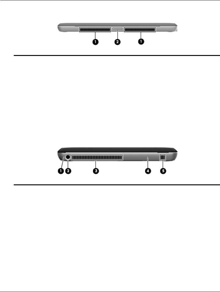
Front components
Item |
Component |
Description |
|
|
|
(1) |
Vents (2) |
Enable airflow to cool internal components. |
|
|
The computer fan starts up automatically to cool internal components |
|
|
and prevent overheating. It is normal for the internal fan to cycle on and |
|
|
off during routine operation. |
|
|
|
(2) |
Digital Media Slot |
Supports the following digital card formats: |
|
|
■ MultiMediaCard |
|
|
■ micro MultiMediaCard (adapter required) |
|
|
■ MultiMediaCard Plus |
|
|
■ Secure Digital Memory Card |
|
|
■ micro Secure Digital Memory Card (adapter required) |
|
|
■ Secure Digital High Capacity Memory Card |
|
|
|
Left-side components
Item |
Component |
Description |
|
|
|
(1) |
Battery light |
■ Off: The computer is running on battery power. |
|
|
■ Blinking amber: The battery has reached a low battery level, a critical |
|
|
battery level, or there is a battery error. |
|
|
■ Amber: A battery is charging. |
|
|
■ White: The computer is connected to external power and the battery is |
|
|
fully charged. |
|
|
|
(2) |
Power connector |
Connects an AC adapter. |
|
|
|
(3) |
Vent |
Enables airflow to cool internal components. |
|
|
The computer fan starts up automatically to cool internal components |
|
|
and prevent overheating. It is normal for the internal fan to cycle on and |
|
|
off during routine operation. |
|
|
|
(4) |
Drive light |
■ Blinking white: The hard drive is being accessed. |
|
|
■ Amber (select models only): HP ProtectSmart Hard Drive Protection has |
|
|
temporarily parked the hard drive. |
|
|
|
(5) |
Speaker |
Produces sound. |
|
|
|
2–8 |
Maintenance and Service Guide |

External component identification
Right-side components
Item |
Component |
Description |
|
|
|
(1) |
Speaker |
Produces sound. |
|
|
|
(2) |
Security cable slot |
Attaches an optional security cable to the computer. |
|
|
The security cable is designed to act as a deterrent, but it may not |
|
|
prevent the computer from being mishandled or stolen. |
|
|
|
(3) |
Audio-out (headphone) jack/Audio-in |
Produces sound when connected to optional powered stereo speakers, |
|
(microphone) jack |
headphones, earbuds, a headset, or television audio. Also connects an |
|
|
optional headset microphone. |
|
|
When a device is connected to the jack, the device speakers |
|
|
are disabled. |
|
|
|
(4) |
eSATA/USB port |
Connects a high-performance eSATA component, such as an eSATA external |
|
|
hard drive, or connects an optional USB device. |
|
|
|
(5) |
USB ports (2) |
Connect optional USB devices. |
|
|
|
(6) |
HDMI port |
Connects an optional video or audio device, such as a high-definition |
|
|
television, or any compatible digital or audio component. |
|
|
|
(7) |
RJ-45 (network) jack |
Connects a network cable. |
|
|
|
(8) |
Vent |
Enables airflow to cool internal components. |
|
|
The computer fan starts up automatically to cool internal components |
|
|
and prevent overheating. It is normal for the internal fan to cycle on and |
off during routine operation.
Maintenance and Service Guide |
2–9 |
External component identification
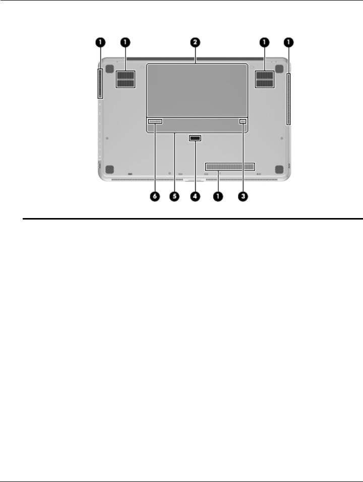
Bottom components
Item |
Component |
Description |
|
|
|
(1) |
Vents (5) |
Enable airflow to cool internal components. |
|
|
The computer fan starts up automatically to cool internal components |
|
|
and prevent overheating. It is normal for the internal fan to cycle on and |
|
|
off during routine operation. |
|
|
|
(2) |
Battery bay |
Holds the primary battery. |
|
|
The primary battery is preinstalled in the battery bay at the factory. |
(3) |
Battery lock |
Locks the primary battery inside the battery bay. |
|
|
|
(4) |
Accessory battery connector |
Connects an optional accessory battery. |
|
|
|
(5) |
Memory module compartment |
Holds the memory modules. |
|
|
|
(6) |
Battery release latch |
Releases the primary battery from the battery bay. |
|
|
|
2–10 |
Maintenance and Service Guide |
3
Illustrated parts catalog
Service tag
When ordering parts or requesting information, provide the computer serial number and model number provided on the service tag.
The battery must be removed to gain access to the service tag. See the “Battery” section in Chapter 4 (“Removal and replacement procedures”) for battery removal and replacement instructions.
Maintenance and Service Guide |
3–1 |

Illustrated parts catalog
Item |
Component |
Description |
|
|
|
(1) |
Serial number (s/n) |
This is an alphanumeric identifier that is unique to each product. |
|
|
|
(2) |
Product name |
This is the product name affixed to the front of the computer. |
|
|
|
(3) |
Model description |
This is the alphanumeric identifier used to locate documents, |
|
|
drivers, and support for the computer. |
|
|
|
(4) |
Warranty period |
This number describes the duration (in years) of the warranty |
|
|
period for the computer. |
|
|
|
(5) |
Part number/Product number (p/n) |
This number provides specific information about the product’s |
|
|
hardware components. The part number helps a service |
|
|
technician determine what components and parts are needed. |
|
|
|
3–2 |
Maintenance and Service Guide |

Illustrated parts catalog
Computer major components
Maintenance and Service Guide |
3–3 |

Illustrated parts catalog
Item Description |
Spare part number |
(1)Display assembly (includes webcam/microphone module and cable, 2 WLAN antenna transceivers and cables, nameplate, and logo):
With bronze finish:
■ 15.6-in, WVA, AntiGlare LED display assembly |
591172-001 |
■ 15.6-in, WVA, BrightView LED display assembly |
576803-001 |
■ 15.6-in, SVA, BrightView LED display assembly |
576802-001 |
|
|
With black finish: |
|
■ 15.6-in, WVA, AntiGlare LED display assembly |
591173-001 |
■ 15.6-in, WVA, BrightView LED display assembly |
580127-001 |
■ 15.6-in, SVA, BrightView LED display assembly |
580126-001 |
(2)Top cover (includes TouchPad board, TouchPad bracket, and TouchPad cable):
|
With bronze finish for use in all countries and regions except Brazil and the United Kingdom |
576840-001 |
|
With bronze finish for use only in Brazil |
576840-201 |
|
With bronze finish for use only in the United Kingdom |
576840-031 |
|
With black finish for use in all countries and regions except the United Kingdom |
580122-001 |
|
With black finish for use only in the United Kingdom |
580122-031 |
|
|
|
(3) |
Keyboard (includes keyboard cable): |
|
|
With bronze finish: |
|
|
■ For use in Belgium |
576835-A41 |
|
■ For use in Brazil |
576835-201 |
|
■ For use in Denmark, Finland, and Norway |
576835-DH1 |
|
■ For use in France |
576835-051 |
|
■ For use in French Canada |
576835-121 |
|
■ For use in Germany |
576835-041 |
|
■ For use in Italy |
576835-061 |
|
■ For use in Latin America |
576835-161 |
|
■ For use in the Netherlands |
576835-B31 |
|
■ For use in Russia |
576835-251 |
|
■ For use in Saudi Arabia |
576835-171 |
|
■ For use in South Korea |
576835-AD1 |
|
■ For use in Spain |
576835-071 |
|
■ For use in Switzerland |
576835-BG1 |
|
■ For use in the United Kingdom and Singapore |
576835-031 |
|
■ For use in the United States |
576835-001 |
(Continued)
3–4 |
Maintenance and Service Guide |

Illustrated parts catalog
Item Description |
Spare part number |
(3)Keyboard (includes keyboard cable) (continued): With black finish:
|
■ For use in France |
580132-051 |
|
■ For use in Saudi Arabia |
580132-171 |
|
■ For use in the United Kingdom and Singapore |
580132-031 |
|
■ For use in the United States |
580132-001 |
|
|
|
|
Keyboard Hardware Kit (not illustrated, includes Mylar shield and screws) |
576836-001 |
|
|
|
(4) |
Memory modules (1066-MHz, PC3): |
|
|
4096-MB |
576817-001 |
|
2048-MB |
576816-001 |
|
|
|
(5) |
RTC battery (includes double-sided tape) |
576848-001 |
|
|
|
(6) |
WLAN module: |
|
|
802.11 a/g/n WLAN module: |
|
|
■ Intel WiFi Link 6200 802.11 a/g/n WLAN module for use in Andorra, |
572509-001 |
|
Antigua and Barbuda, Argentina, Aruba, Australia, Austria, Azerbaijan, Bahamas, |
|
|
Bahrain, Barbados, Belgium, Bermuda, Bolivia, Bosnia, Brazil, Brunei, Bulgaria, Canada, |
|
|
the Cayman Islands, Chile, Colombia, Costa Rica, Croatia, Cyprus, the Czech Republic, |
|
|
Denmark, the Dominican Republic, Ecuador, Egypt, El Salvador, Estonia, Finland, |
|
|
France, French Guiana, Georgia, Germany, Ghana, Greece, Guadeloupe, Guam, |
|
|
Guatemala, Haiti, Herzegovina, Honduras, Hong Kong, Hungary, Iceland, India, |
|
|
Indonesia, Ireland, Israel, Italy, the Ivory Coast, Jamaica, Japan, Jordan, Kenya, Kuwait, |
|
|
Kyrgyzstan, Latvia, Lebanon, Liechtenstein, Lithuania, Luxembourg, Malawi, Malaysia, |
|
|
Malta, Martinique, Mauritius, Mexico, Monaco, Montenegro, Morocco, the Nether Antilles, |
|
|
the Netherlands, New Zealand, Nicaragua, Nigeria, Norway, Oman, Panama, Paraguay, |
|
|
the People’s Republic China, Peru, the Philippines, Poland, Portugal, Puerto Rico, Qatar, |
|
|
Romania, San Marino, Saudi Arabia, Senegal, Serbia, Singapore, Slovakia, Slovenia, |
|
|
South Africa, South Korea, Spain, Sweden, Switzerland, Taiwan, Tanzania, Thailand, |
|
|
Trinidad and Tobago, Turkey, the United Arab Emirates, the United Kingdom, Uruguay, |
|
|
the U.S. Virgin Islands, the United States, Venezuela, and Vietnam |
|
|
■ Intel WiFi Link 5100 802.11 a/g/n WLAN module for use in Andorra, |
572507-001 |
|
Antigua and Barbuda, Argentina, Aruba, Australia, Austria, Azerbaijan, Bahamas, |
|
|
Bahrain, Barbados, Belgium, Bermuda, Bolivia, Bosnia, Brazil, Brunei, Bulgaria, Canada, |
|
|
the Cayman Islands, Chile, Colombia, Costa Rica, Croatia, Cyprus, the Czech Republic, |
|
|
Denmark, the Dominican Republic, Ecuador, Egypt, El Salvador, Estonia, Finland, |
|
|
France, French Guiana, Georgia, Germany, Ghana, Greece, Guadeloupe, Guam, |
|
|
Guatemala, Haiti, Herzegovina, Honduras, Hong Kong, Hungary, Iceland, India, |
|
|
Indonesia, Ireland, Israel, Italy, the Ivory Coast, Jamaica, Japan, Jordan, Kenya, Kuwait, |
|
|
Kyrgyzstan, Latvia, Lebanon, Liechtenstein, Lithuania, Luxembourg, Malawi, Malaysia, |
|
|
Malta, Martinique, Mauritius, Mexico, Monaco, Montenegro, Morocco, the Nether Antilles, |
|
|
the Netherlands, New Zealand, Nicaragua, Nigeria, Norway, Oman, Panama, Paraguay, |
|
|
the People’s Republic China, Peru, the Philippines, Poland, Portugal, Puerto Rico, Qatar, |
|
|
Romania, San Marino, Saudi Arabia, Senegal, Serbia, Singapore, Slovakia, Slovenia, |
|
|
South Africa, South Korea, Spain, Sweden, Switzerland, Taiwan, Tanzania, Thailand, |
|
|
Trinidad and Tobago, Turkey, the United Arab Emirates, the United Kingdom, Uruguay, |
|
|
the U.S. Virgin Islands, the United States, Venezuela, and Vietnam |
|
(Continued)
Maintenance and Service Guide |
3–5 |

Illustrated parts catalog
Item |
Description |
Spare part number |
|
|
|
(6) |
WLAN module (continued): |
|
|
802.11 a/b/g WLAN module: |
|
|
■ Intel WiFi Link 6100 802.11 a/b/g WLAN module for use in Andorra, |
572510-001 |
|
Antigua and Barbuda, Argentina, Aruba, Australia, Austria, Azerbaijan, Bahamas, |
|
|
Bahrain, Barbados, Belgium, Bermuda, Bolivia, Bosnia, Brazil, Brunei, Bulgaria, Canada, |
|
|
the Cayman Islands, Chile, Colombia, Costa Rica, Croatia, Cyprus, the Czech Republic, |
|
|
Denmark, the Dominican Republic, Ecuador, Egypt, El Salvador, Estonia, Finland, |
|
|
France, French Guiana, Georgia, Germany, Ghana, Greece, Guadeloupe, Guam, |
|
|
Guatemala, Haiti, Herzegovina, Honduras, Hong Kong, Hungary, Iceland, India, |
|
|
Indonesia, Ireland, Israel, Italy, the Ivory Coast, Jamaica, Japan, Jordan, Kenya, Kuwait, |
|
|
Kyrgyzstan, Latvia, Lebanon, Liechtenstein, Lithuania, Luxembourg, Malawi, Malaysia, |
|
|
Malta, Martinique, Mauritius, Mexico, Monaco, Montenegro, Morocco, the Nether Antilles, |
|
|
the Netherlands, New Zealand, Nicaragua, Nigeria, Norway, Oman, Panama, Paraguay, |
|
|
the People’s Republic China, Peru, the Philippines, Poland, Portugal, Puerto Rico, Qatar, |
|
|
Romania, San Marino, Saudi Arabia, Senegal, Serbia, Singapore, Slovakia, Slovenia, |
|
|
South Africa, South Korea, Spain, Sweden, Switzerland, Taiwan, Tanzania, Thailand, |
|
|
Trinidad and Tobago, Turkey, the United Arab Emirates, the United Kingdom, Uruguay, |
|
|
the U.S. Virgin Islands, the United States, Venezuela, and Vietnam |
|
|
■ Intel WiFi Link 5100 802.11 a/b/g WLAN module for use in Andorra, |
572508-001 |
|
Antigua and Barbuda, Argentina, Aruba, Australia, Austria, Azerbaijan, Bahamas, |
|
|
Bahrain, Barbados, Belgium, Bermuda, Bolivia, Bosnia, Brazil, Brunei, Bulgaria, Canada, |
|
|
the Cayman Islands, Chile, Colombia, Costa Rica, Croatia, Cyprus, the Czech Republic, |
|
|
Denmark, the Dominican Republic, Ecuador, Egypt, El Salvador, Estonia, Finland, |
|
|
France, French Guiana, Georgia, Germany, Ghana, Greece, Guadeloupe, Guam, |
|
|
Guatemala, Haiti, Herzegovina, Honduras, Hong Kong, Hungary, Iceland, India, |
|
|
Indonesia, Ireland, Israel, Italy, the Ivory Coast, Jamaica, Japan, Jordan, Kenya, Kuwait, |
|
|
Kyrgyzstan, Latvia, Lebanon, Liechtenstein, Lithuania, Luxembourg, Malawi, Malaysia, |
|
|
Malta, Martinique, Mauritius, Mexico, Monaco, Montenegro, Morocco, the Nether Antilles, |
|
|
the Netherlands, New Zealand, Nicaragua, Nigeria, Norway, Oman, Panama, Paraguay, |
|
|
the People’s Republic China, Peru, the Philippines, Poland, Portugal, Puerto Rico, Qatar, |
|
|
Romania, San Marino, Saudi Arabia, Senegal, Serbia, Singapore, Slovakia, Slovenia, |
|
|
South Africa, South Korea, Spain, Sweden, Switzerland, Taiwan, Tanzania, Thailand, |
|
|
Trinidad and Tobago, Turkey, the United Arab Emirates, the United Kingdom, Uruguay, |
|
|
the U.S. Virgin Islands, the United States, Venezuela, and Vietnam |
|
|
Intel 1000 802.11 b/g/n WLAN module for use in Andorra, Antigua and Barbuda, Argentina, |
572520-001 |
|
Aruba, Australia, Austria, Azerbaijan, Bahamas, Bahrain, Barbados, Belgium, Bermuda, |
|
|
Bolivia, Bosnia, Brazil, Brunei, Bulgaria, Canada, the Cayman Islands, Chile, Colombia, |
|
|
Costa Rica, Croatia, Cyprus, the Czech Republic, Denmark, the Dominican Republic, |
|
|
Ecuador, Egypt, El Salvador, Estonia, Finland, France, French Guiana, Georgia, Germany, |
|
|
Ghana, Greece, Guadeloupe, Guam, Guatemala, Haiti, Herzegovina, Honduras, |
|
|
Hong Kong, Hungary, Iceland, India, Indonesia, Ireland, Israel, Italy, the Ivory Coast, |
|
|
Jamaica, Japan, Jordan, Kenya, Kuwait, Kyrgyzstan, Latvia, Lebanon, Liechtenstein, |
|
|
Lithuania, Luxembourg, Malawi, Malaysia, Malta, Martinique, Mauritius, Mexico, Monaco, |
|
|
Montenegro, Morocco, the Nether Antilles, the Netherlands, New Zealand, Nicaragua, |
|
|
Nigeria, Norway, Oman, Panama, Paraguay, the People’s Republic China, Peru, |
|
|
the Philippines, Poland, Portugal, Puerto Rico, Qatar, Romania, San Marino, Saudi Arabia, |
|
|
Senegal, Serbia, Singapore, Slovakia, Slovenia, South Africa, South Korea, Spain, Sweden, |
|
|
Switzerland, Taiwan, Tanzania, Thailand, Trinidad and Tobago, Turkey, |
|
|
the United Arab Emirates, the United Kingdom, Uruguay, the U.S. Virgin Islands, |
|
|
the United States, Venezuela, and Vietnam |
|
(Continued)
3–6 |
Maintenance and Service Guide |

Illustrated parts catalog
Item Description |
Spare part number |
(6)WLAN module (continued):
|
Intel 1000 802.11 b/g WLAN module for use in Andorra, Antigua and Barbuda, Argentina, |
585984-001 |
|
Aruba, Australia, Austria, Azerbaijan, Bahamas, Bahrain, Barbados, Belgium, Bermuda, |
|
|
Bolivia, Bosnia, Brazil, Brunei, Bulgaria, Canada, the Cayman Islands, Chile, Colombia, |
|
|
Costa Rica, Croatia, Cyprus, the Czech Republic, Denmark, the Dominican Republic, |
|
|
Ecuador, Egypt, El Salvador, Estonia, Finland, France, French Guiana, Georgia, Germany, |
|
|
Ghana, Greece, Guadeloupe, Guam, Guatemala, Haiti, Herzegovina, Honduras, |
|
|
Hong Kong, Hungary, Iceland, India, Indonesia, Ireland, Israel, Italy, the Ivory Coast, |
|
|
Jamaica, Japan, Jordan, Kenya, Kuwait, Kyrgyzstan, Latvia, Lebanon, Liechtenstein, |
|
|
Lithuania, Luxembourg, Malawi, Malaysia, Malta, Martinique, Mauritius, Mexico, Monaco, |
|
|
Montenegro, Morocco, the Nether Antilles, the Netherlands, New Zealand, Nicaragua, |
|
|
Nigeria, Norway, Oman, Panama, Paraguay, the People’s Republic China, Peru, |
|
|
the Philippines, Poland, Portugal, Puerto Rico, Qatar, Romania, San Marino, Saudi Arabia, |
|
|
Senegal, Serbia, Singapore, Slovakia, Slovenia, South Africa, South Korea, Spain, Sweden, |
|
|
Switzerland, Taiwan, Tanzania, Thailand, Trinidad and Tobago, Turkey, |
|
|
the United Arab Emirates, the United Kingdom, Uruguay, the U.S. Virgin Islands, |
|
|
the United States, Venezuela, and Vietnam |
|
|
|
|
(7a) |
Hard drive (includes bracket, rubber isolators, and screws): |
|
|
2.5-in, 7200-rpm: |
|
|
■ 640-GB |
576821-001 |
|
■ 500-GB |
576820-001 |
|
■ 320-GB |
576819-001 |
|
■ 250-GB |
576818-001 |
|
|
|
|
1.8-in, 5400-rpm: |
|
|
■ 320-GB |
576823-001 |
|
■ 250-GB |
580129-001 |
|
■ 160-GB |
591171-001 |
|
|
|
(7b) |
Hard drive cable: |
|
|
For use only with 2.5-in hard drives |
576828-001 |
|
For use only with 1.8-in hard drives |
576830-001 |
|
|
|
|
Hard Drive Hardware Kit (not illustrated, includes bracket, rubber isolators, and screws): |
|
|
For use only with 2.5-in hard drives |
576827-001 |
|
For use only with 1.8-in hard drives |
576829-001 |
|
|
|
(8) |
Speaker assembly |
576842-001 |
|
|
|
(9) |
Processor fan/heat sink assembly (includes replacement thermal material) |
576837-001 |
(10)Processor (includes replacement thermal material):
|
Intel Core i7-820QM 1.73-GHz processor (SC turbo up to 3.06-GHz) |
583053-001 |
|
Intel Core i7-720QM 1.60-GHz processor (SC turbo up to 2.80-GHz) |
586170-001 |
|
|
|
(11) |
Video fan/heat sink assembly (includes replacement thermal material) |
576838-001 |
|
|
|
(12) |
Power button board and cable (includes double-sided tape) |
576849-001 |
|
|
|
(13) |
Power connector cable (includes bracket) |
576846-001 |
(Continued)
Maintenance and Service Guide |
3–7 |

Illustrated parts catalog
Item |
Description |
Spare part number |
|
|
|
(14) |
PM57 PCH Peak-M system board with 1 GB of dedicated video memory |
576772-001 |
|
(includes replacement thermal material) |
|
(15)Base enclosure (includes 4 rubber feet):
|
With bronze finish |
576839-001 |
|
With black finish |
580121-001 |
|
|
|
|
Rubber Feet Kit (not illustrated, includes 4 rubber feet) |
538346-001 |
|
|
|
(16) |
Battery: |
|
|
9-cell, 2.80-Ah (93-Wh) Li-ion battery |
576834-001 |
|
6-cell, 2.40-Ah (53-Wh) Li-ion battery |
576833-001 and |
|
|
586025-001 |
(17)Memory module compartment cover (included in the Plastics Kit, spare part number 576847-001)
3–8 |
Maintenance and Service Guide |
Illustrated parts catalog
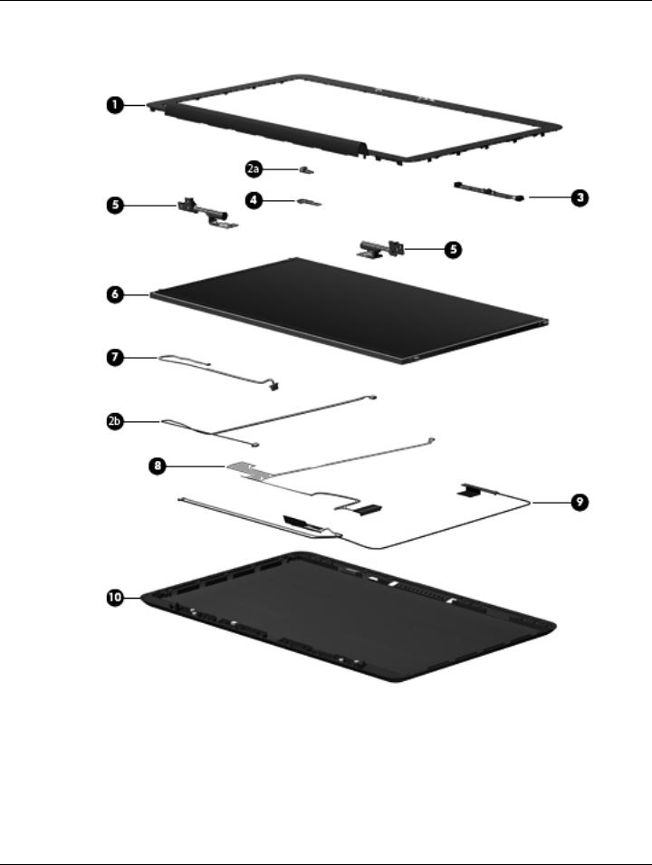
Display components
Maintenance and Service Guide |
3–9 |

Illustrated parts catalog
Item |
Description |
Spare part number |
|
|
|
(1) |
Display bezel |
576810-001 |
|
|
|
(2a) |
Ambient light sensor module (includes cable and double-sided tape) |
576815-001 |
(2b) |
Ambient light sensor module cable (included in the ambient light sensor module spare part kit) |
|
|
|
|
(3) |
Webcam/microphone module |
576812-001 |
|
|
|
(4) |
Bluetooth module |
537921-001 |
The Bluetooth module spare part kit does not include a Bluetooth module cable. The Bluetooth module cable is available using spare part number 576845-001.
(5)Display left and right hinges (included in the Display Hinge Kit, spare part number 576809-001)
(6)Display panel:
|
For use only with the 15.6-in, WVA, AntiGlare LED display assembly |
591327-001 |
|
For use only with the 15.6-in, WVA, BrightView LED display assembly |
576801-001 |
|
For use only with the 15.6-in, SVA, BrightView LED display assembly |
576800-001 |
|
|
|
(7) |
Bluetooth module cable |
576845-001 |
|
|
|
(8) |
Display panel cable (includes double-sided tape) |
576813-001 |
|
|
|
(9) |
Wireless antenna transceivers and cables |
576814-001 |
(10)Display enclosure:
|
With bronze finish |
576811-001 |
|
With black finish |
580128-001 |
|
|
|
|
Display Screw Kit (not illustrated) |
576808-001 |
|
|
|
3–10 |
Maintenance and Service Guide |
Loading...