


GPS Navigator
GP-33
W3D
www.furuno.co.jp

The paper used in this manual is elemental chlorine free.
9-52 Ashihara-cho,
Nishinomiya, 662-8580, JAPAN
Telephone : +81-(0)798-65-2111
Fax |
: +81-(0)798-65-4200 |
All rights reserved. |
Printed in Japan |
Pub. No. OME-44580-C1
(YOTA ) GP-33
FURUNO Authorized Distributor/Dealer
A : JAN. 2010
C1 : JAN. 31, 2011
*00017317712*
*00017317712*
* 0 0 0 1 7 3 1 7 7 1 2 *

IMPORTANT NOTICE
General
•The operator of this equipment must read and follow the descriptions in this manual. Wrong operation or maintenance can cancel the warranty or cause injury.
•Do not copy any part of this manual without written permission from FURUNO.
•If this manual is lost or worn, contact your dealer about replacement.
•The contents of this manual and equipment specifications can change without notice.
•The example screens (or illustrations) shown in this manual can be different from the screens you see on your display. The screens you see depend on your system configuration and equipment settings.
•Save this manual for future reference.
•Any modification of the equipment (including software) by persons not authorized by FURUNO will cancel the warranty.
•All brand and product names are trademarks, registered trademarks or service marks of their respective holders.
How to discard this product
Discard this product according to local regulations for the disposal of industrial waste. For disposal in the USA, see the homepage of the Electronics Industries Alliance (http://www.eiae.org/) for the correct method of disposal.
How to discard a used battery
Some FURUNO products have a battery(ies). To see if your product has a battery(ies), see the chapter on Maintenance. Follow the instructions below if a battery(ies) is used. Tape the + and - terminals of battery before dispossal to prevent fire, heat generation caused by short circuit.
In the European Union
The crossed-out trash can symbol indicates that all types of batteries |
|
must not be discarded in standard trash, or at a trash site. Take the |
|
used batteries to a battery collection site according to your national |
Cd |
legislation and the Batteries Directive 2006/66/EU. |
In the USA
The Mobius loop symbol (three chasing arrows) indicates that Ni-Cd and lead-acid rechargeable batteries must be recycled. Take the used
batteries to a battery collection site according to local laws.
Ni-Cd Pb
In the other countries
There are no international standards for the battery recycle symbol. The number of symbols can increase when the other countries make their own recycle symbols in the future.
i

SAFETY INSTRUCTIONS
|
|
|
|
|
|
|
|
|
|
|
WARNING |
Indicates a condition that can cause death or serious |
|
|
|
injury if not avoided. |
|
||
|
|
|
|
|
|
CAUTION |
Indicates a condition that can cause minor or moderate |
||
|
injury if not avoided. |
|||
Safety Instructions for the Operator |
Safety Instructions for the Installer |
|||
WARNING
Do not disassemble or modify the equipment.
Fire, electrical shock or serious injury can occur.
Turn off the power immediately if water leaks into the equipment or smoke or fire is coming from the equipment.
Failure to turn off the equipment can cause fire or electrical shock. Contact a FURUNO agent for service.
CAUTION
The glass of an LCD panel breaks easily. Handle the LCD carefully.
Injury can result if the glass breaks.
No single navigation aid (including this unit) should ever be relied upon as the exclusive means for navigating your vessel.
The navigator is responsible for checking all aids available to confirm his position. Electronic aids are intended to assist, not replace, the navigator.
WARNING
Turn off the power at the switchboard before you install the equipment.
Fire or electrical shock can occur if the power is left on.
Be sure that the power supply is compatible with the voltage rating of the equipment.
Connection of an incorrect power supply can cause fire or equipment damage. The voltage rating of the equipment appears on the label above the power connector.
CAUTION
Ground the equipment to prevent mutual interference.
Observe the following compass safe distances to prevent interference to a magnetic compass:
Model
Standard Steering compass compass
GP-33 0.65 m 0.45 m
ii
TABLE OF CONTENTS
|
|
|
|
....................................................................................................................FOREWORD |
v |
||
SYSTEM CONFIGURATION .......................................................................................... |
vi |
||
1. |
OPERATIONAL OVERVIEW................................................................................. |
1-1 |
|
|
1.1 |
Controls ...................................................................................................................... |
1-1 |
|
1.2 |
How to Turn Power On/Off ......................................................................................... |
1-2 |
|
1.3 |
How to Adjust LCD and Key Panel Brilliance ............................................................. |
1-3 |
|
1.4 |
Display Modes............................................................................................................ |
1-3 |
|
1.5 |
Menu Overview........................................................................................................... |
1-8 |
|
1.6 |
How to Enter the MOB Mark....................................................................................... |
1-9 |
2. |
PLOTTER DISPLAY OVERVIEW.......................................................................... |
2-1 |
|
|
2.1 |
How to Select the Display Range............................................................................... |
2-1 |
|
2.2 |
How to Shift the Cursor .............................................................................................. |
2-1 |
|
2.3 |
How to Shift the Display ............................................................................................. |
2-2 |
|
2.4 |
How to Change Track Plotting Interval, Stop Recording ............................................ |
2-3 |
|
2.5 |
How to Change Track Color ....................................................................................... |
2-4 |
|
2.6 |
How to Erase Track.................................................................................................... |
2-4 |
|
|
2.6.1 How to erase track by color............................................................................ |
2-4 |
|
|
2.6.2 How to erase all tracks ................................................................................... |
2-5 |
3. |
WAYPOINTS.......................................................................................................... |
3-1 |
|
|
3.1 |
How to Enter Waypoints ............................................................................................. |
3-1 |
|
|
3.1.1 How to enter a waypoint with the cursor ........................................................ |
3-1 |
|
|
3.1.2 How to enter a waypoint at own boat position................................................ |
3-1 |
|
|
3.1.3 How to enter a waypoint through the list ........................................................ |
3-1 |
|
|
3.1.4 How to enter waypoints automatically ............................................................ |
3-3 |
|
3.2 |
How to Display Waypoint Name ................................................................................. |
3-4 |
|
3.3 |
How to Edit Waypoints ............................................................................................... |
3-5 |
|
|
3.3.1 How to edit waypoints on the plotter display .................................................. |
3-5 |
|
|
3.3.2 How to edit waypoints through the list............................................................ |
3-5 |
|
3.4 |
How to Move Waypoints............................................................................................. |
3-6 |
|
3.5 |
How to Erase Waypoints ............................................................................................ |
3-7 |
|
|
3.5.1 How to erase a waypoint on the plotter display.............................................. |
3-7 |
|
|
3.5.2 How to erase a waypoint through the waypoint list ........................................ |
3-7 |
|
|
3.5.3 How to erase all waypoints............................................................................. |
3-8 |
4. |
ROUTES ................................................................................................................ |
4-1 |
|
|
4.1 |
How to Create Routes ................................................................................................ |
4-1 |
|
4.2 |
How to Edit Routes..................................................................................................... |
4-3 |
|
|
4.2.1 How to replace a waypoint in a route ............................................................. |
4-3 |
|
|
4.2.2 How to delete a waypoint from a route........................................................... |
4-3 |
|
|
4.2.3 How to insert a waypoint in a route ................................................................ |
4-4 |
|
|
4.2.4 How to temporarily deselect a waypoint in a route......................................... |
4-4 |
|
4.3 |
How to Erase a Route ................................................................................................ |
4-5 |
|
|
4.3.1 How to erase a route through the route list .................................................... |
4-5 |
|
|
4.3.2 How to erase all routes................................................................................... |
4-5 |
5. |
DESTINATION ....................................................................................................... |
5-1 |
|
|
5.1 |
How to Set Destination by Cursor Position................................................................. |
5-1 |
|
5.2 |
How to Set Destination by Waypoint .......................................................................... |
5-2 |
|
|
5.2.1 How to set a destination waypoint with the cursor ......................................... |
5-2 |
iii
TABLE OF CONTENTS |
|
|||
|
|
5.2.2 How to set a destination waypoint through the list |
......................................... 5-2 |
|
|
5.3 |
How to Set Route as Destination ............................................................................... |
5-2 |
|
|
5.4 |
How to Cancel Destination......................................................................................... |
5-3 |
|
|
|
5.4.1 How to cancel destination with the cursor...................................................... |
5-3 |
|
|
|
5.4.2 How to cancel destination through the list...................................................... |
5-4 |
|
6. |
ALARMS ................................................................................................................ |
|
6-1 |
|
|
6.1 |
Overview .................................................................................................................... |
6-1 |
|
|
6.2 |
Buzzer Type Selection ............................................................................................... |
6-2 |
|
|
6.3 |
How to Set an Alarm .................................................................................................. |
6-2 |
|
|
6.4 |
Alarm Descriptions ..................................................................................................... |
6-4 |
|
7. |
OTHER FUNCTIONS ............................................................................................. |
7-1 |
||
|
7.1 |
Plotter Setup Menu .................................................................................................... |
7-1 |
|
|
7.2 |
GPS Setup Menu ....................................................................................................... |
7-2 |
|
|
7.3 |
WAAS Menu............................................................................................................... |
7-4 |
|
|
7.4 |
Position Display Format ............................................................................................. |
7-4 |
|
|
7.5 |
System Menu ............................................................................................................. |
7-5 |
|
|
7.6 |
User Display Menu..................................................................................................... |
7-7 |
|
|
7.7 |
I/O Setup Menu ........................................................................................................ |
7-10 |
|
|
|
7.7.1 Uploading data to a PC................................................................................ |
7-13 |
|
|
|
7.7.2 Downloading data from PC .......................................................................... |
7-13 |
|
8. |
MAINTENANCE, TROUBLESHOOTING............................................................... |
8-1 |
||
|
8.1 |
Maintenance............................................................................................................... |
8-1 |
|
|
8.2 |
Troubleshooting ......................................................................................................... |
8-2 |
|
|
8.3 |
Displaying the Message Board .................................................................................. |
8-3 |
|
|
8.4 |
Diagnostics................................................................................................................. |
8-3 |
|
|
8.5 |
Clearing Data ............................................................................................................. |
8-4 |
|
9. |
INSTALLATION ..................................................................................................... |
9-1 |
||
|
9.1 |
Equipment Lists.......................................................................................................... |
9-1 |
|
|
9.2 |
Installation of Receiver Unit ....................................................................................... |
9-1 |
|
|
|
9.2.1 |
Installation consideration................................................................................ |
9-1 |
|
|
9.2.2 Desktop and underside of table mount .......................................................... |
9-2 |
|
|
|
9.2.3 |
Flush mount ................................................................................................... |
9-3 |
|
9.3 |
Installation of Antenna Unit ........................................................................................ |
9-4 |
|
|
9.4 |
Wiring ......................................................................................................................... |
|
9-5 |
|
9.5 |
Language Setting ....................................................................................................... |
9-8 |
|
|
9.6 |
Input/Output Data....................................................................................................... |
9-8 |
|
APPENDIX 1 MENU TREE ....................................................................................... |
AP-1 |
|||
APPENDIX 2 WHAT IS WAAS? ............................................................................... |
AP-3 |
|||
APPENDIX 3 LIST OF TERMS ................................................................................. |
AP-4 |
|||
APPENDIX 4 GEODETIC CHART LIST ................................................................... |
AP-5 |
|||
SPECIFICATIONS ..................................................................................................... |
SP-1 |
|||
INSTALLATION MATERIALS, ACCESSORIES......................................................... |
A-1 |
|||
OUTLINE DRAWINGS................................................................................................. |
D-1 |
|||
INTERCONNECTION DIAGRAM ................................................................................ |
S-1 |
|||
INDEX.......................................................................................................................... |
|
|
IN-1 |
|
iv

FOREWORD
A Word to the Owner of the GP-33
Congratulations on your choice of the GP-33 GPS Navigator.
For over 60 years FURUNO Electric Company has enjoyed an enviable reputation for innovative and dependable marine electronics is furthered by our extensive global network of agents and dealers.
Your navigator is designed and constructed to meet the rigorous demands of the marine environment. However, no machine can perform its intended function unless installed, operated and maintained properly. Please carefully read and follow the recommended procedures for installation, operation and maintenance.
We would appreciate feedback from you, the end-user, about where we are achieving our purposes.
Thank you for considering and purchasing FURUNO equipment.
Features
The main features of the GP-33 are as shown below.
•High-resolution color LCD
•WAAS capability
•Storage for 10,000 waypoints, 100 routes and 3,000 track points
•Alarms: Arrival/Anchor, XTE (Cross-track Error), Trip, Odometer, Time, WAAS and Speed
•Man overboard feature records position at time of man overboard and provides continuous updates of range and bearing when navigating to the MOB position.
•Unique Highway display provides a graphic presentation of boat’s progress toward a waypoint.
•User-programmable nav data displays provide analog and digital navigation data.
•Navigation data output to the autopilot when connecting.
•Waypoint and route data can be uploaded from a PC and downloaded to a PC.
Program No.
Name |
No. |
Ver. |
|
|
|
CPU MAIN |
2051530-01.** |
January, 2010 |
|
|
|
CPU Boot |
2051531-01.** |
January, 2010 |
|
|
|
CPU CAN LD |
2051532-01.** |
January, 2010 |
|
|
|
GPS |
48502640-** |
January, 2010 |
|
|
|
**: Minor change
v
SYSTEM CONFIGURATION
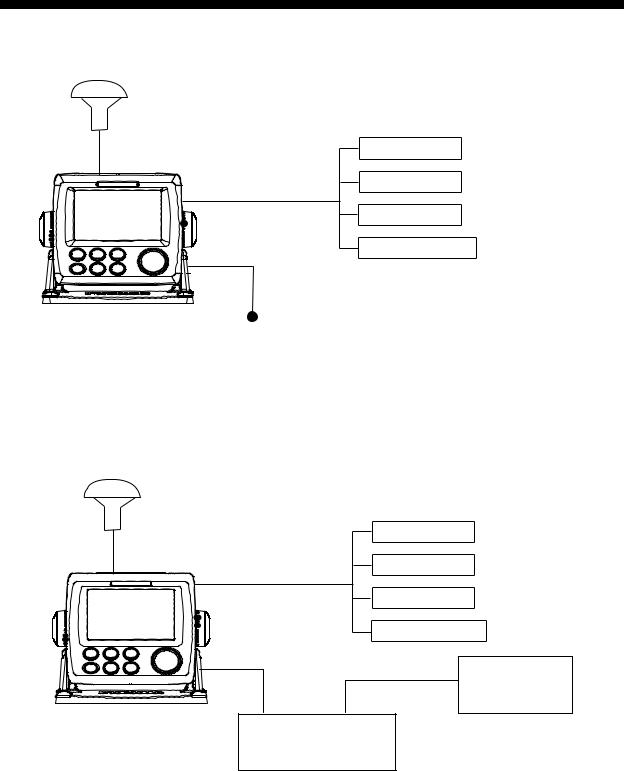
Standalone system
Antenna Unit
GPA-017
Navigation
PC
MOB Switch
External Alarm
Receiver Unit
GP-33 12-24VDC
Standard configuration is shown with solid line.
CAN bus network
When optional junction box FI-5002 is connected
Antenna Unit |
Navigation |
|
GPA-017 |
||
|
||
|
PC |
|
|
MOB Switch |
|
|
External Alarm |
FI-504/507
Receiver Unit
GP-33 Junction Box
FI-5002
 12 VDC
vi
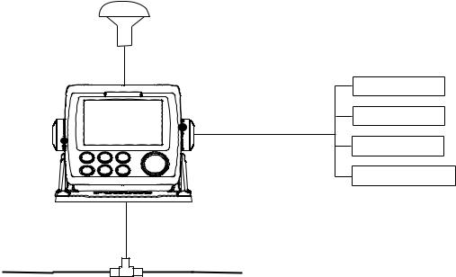
SYSTEM CONFIGURATION
When no FI-5002 is connected
Antenna Unit
GPA-017
Navigation
PC
MOB Switch
External Alarm
Receiver Unit
GP-33
Backbone cable
Category of Units
Units |
Category |
|
|
Antenna Unit GPA-017 |
Exposed to weather |
|
|
Receiver Unit GP-33 |
Protected from weather |
|
|
Junction Box FI-5002 (Option) |
|
|
|
vii
SYSTEM CONFIGURATION
This page is intentionally left blank.
viii
1.OPERATIONAL OVERVIEW
1.1Controls
W3D
Key |
Description |
Selects display mode.
DISP
Sets destination.
GO TO
-Opens the Menu. (plotter and highway displays: twice, others: once) MENU -Shows the zoom window (plotter and highway displays only).
ZOOM
-Shifts the cursor. -Selects item on menus.
(Cursorpad)
-Long press: Turns power off.
-Momentary press: Turns power on./Shows Brill window.
B
RILL
-Long press: Inscribes MOB mark.
WPT -Momentary press: Registers own boat position as MOB position.
MOB
-Long press: Returns own boat position to center (plotter display only).
-Momentary press: Confirms selection on menus.
ENT
1-1
1. OPERATIONAL OVERVIEW
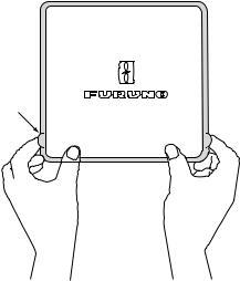
How to detach the hard cover from the unit
Put your thumbs on the front and forefingers on the catches at the sides of the cover, and pull it toward you.
Catches
1.2How to Turn Power On/Off
1.Press the  /BRILL key to turn on the power. The unit beeps and then starts up with the last-used display mode. Your equipment takes about 90 seconds to find its position. The equipment shows receiver status indication at the top left-hand corner in most display modes. The table below shows these indications and their meanings.
|
|
Status indications |
Indication |
|
Meaning |
|
|
|
2D |
2D |
GPS position fixed |
|
|
|
3D |
3D |
GPS position fixed |
|
|
|
W2D |
2D |
WAAS position fixed |
|
|
|
W3D |
3D |
WAAS position fixed |
|
|
|
DOP* |
2D: HDOP larger than 4 |
|
|
3D: PDOP larger than 6 |
|
|
|
|
SIM |
Simulation mode |
|
|
|
|
- - - |
Not fixed |
|
|
|
|
*: DOP (Dilution of Precision) is the index of position accuracy, and it is the distribution pattern of satellites used in position fixing. Generally, the smaller the figure the better the position accuracy. (HDOP: Horizontal DOP, PDOP: Position DOP)
2.To turn off the power, press and hold down the  /BRILL key for three seconds. The time remaining until the power is turned off is counted down on the display.
1-2
1. OPERATIONAL OVERVIEW
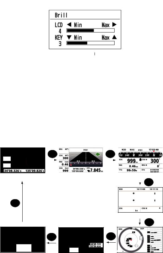
1.3How to Adjust LCD and Key Panel Brilliance
1. Press the  /BRILL key to show the following window.
2.To adjust the LCD brilliance, press  /BRILL key.
The setting changes “0→1→…→7→6…0→1…” continuously. Maximum setting is 7. You can use also the cursorpad (W, X) to adjust the brilliance.
3.To adjust the panel brilliance, press the cursorpad (S, T, max: 7).
4.Press ENT or MENU/ZOOM key.
1.4Display Modes
Your unit has seven display modes: Plotter Display, Highway Display, Steering Display, Nav Data Display, Satellite Monitor Display and User Display 1/2. Press the DISP key to select a display mode. Each time the key is pressed, the display mode changes in the sequence shown below. To step through the displays in reverse order, press the DISP key more than three seconds.
20.0
350
|
|
DISP |
299 |
|
|
|
|
|
|
|
DISP |
|
|
|
|
|
|
|
|
|
|
|||||
|
|
|
|
|
|
|
|
|
|
|
|
|
|
|
|
|
|
|
|
|
|
|
||||
|
|
|
|
|
|
|
|
|
|
|
|
|
|
|
|
|
|
|
|
|
|
|
|
|
|
|
|
|
|
|
166 |
|
|
|
|
|
|
|
|
|
|
|
|
|
|
|
|
|
|
||||
|
|
|
|
|
|
|
|
|
|
|
|
|
|
|
|
|
14.6 |
|
300 |
|
||||||
|
|
|
|
|
|
|
|
|
|
|
|
|
|
|
|
|
|
|
|
|
||||||
|
|
|
|
|
|
|
|
|
|
|
|
|
|
|
|
|||||||||||
|
|
|
|
|
|
|
|
|
|
|
|
|
|
|
|
|||||||||||
|
|
|
|
|
0.46 |
|
|
|
|
|
|
|
|
|
|
|
|
|
|
|
|
|
|
|||
|
|
|
|
|
|
|
|
|
|
|
|
|
|
|
|
|
|
|
|
|
|
|
||||
|
|
|
|
|
|
|
|
|
|
|
|
|
|
|
|
0.46 |
|
|
299 |
|
||||||
|
|
|
|
|
|
|
|
|
|
|
|
|
|
|
|
|
|
|
|
|
||||||
|
|
|
|
|
|
|
|
|
|
|
|
|
|
|
|
|
|
|
|
|
|
|
|
|
|
|
|
|
|
|
|
|
|
|
|
|
N |
|
|
|
|
|
|
|
|
|
|
|
|
|
|
||
|
|
|
|
|
|
|
|
|
|
|
|
|
|
|
|
|
00 |
|
15 |
|
|
|
|
|||
|
|
|
|
|
14.6 |
|
|
|
|
|
|
|
|
|
|
|
|
|
|
|||||||
|
|
|
|
|
|
|
|
|
|
E |
|
|
|
|
|
|||||||||||
|
|
|
|
|
|
|
|
|
|
|
|
|
|
|
|
|
|
|
|
|
|
|
||||
|
|
|
|
|
|
|
|
|
|
|
|
|
|
|
|
|
|
|
|
|
|
|
|
|
|
|
|
|
|
|
|
|
|
|
|
|
|
|
|
|
|
|
|
|
|
|
|
|
|
|
|
|
|
[1]: Plotter display |
[2]: Highway display |
[3]: Steering display |
|
|
|
|
DISP |
|
|
|
|
|
|
34 44.589 N |
||
DISP |
|
135 21.074 E |
||
|
|
14.6 |
|
300 |
|
|
[4]: Nav Data display |
||
|
|
|
|
DISP |
|
|
11 |
|
02 |
|
|
|
1.60 |
05 |
|
|
|
|
08 |
|
DISP |
DISP |
05 |
11 |
|
15 |
|||
|
|
2208 |
|
13 |
|
|
02 |
17 |
|
|
|
13 |
|
22 |
40.0 |
N |
17 |
|
25 |
E |
3230 |
25 |
28 |
|
40.0 |
12.0 |
|
133 |
|
|
|
|
|
30 |
|
|
|
|
32 |
[7]: User display 2 |
[6]: User display 1 |
[5]: Satellite Monitor display |
||
1-3
1. OPERATIONAL OVERVIEW
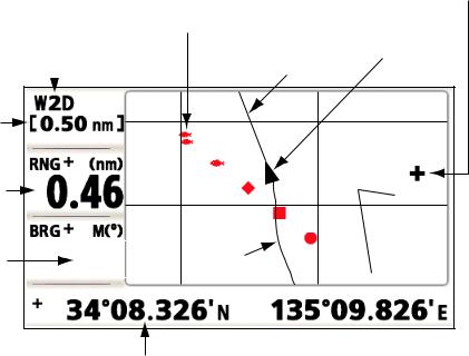
Plotter Display
The plotter display traces own boat’s track.
|
|
Cursor |
|
Waypoint mark |
(displayed for approx. |
|
seven seconds) |
|
|
(Shape selectable) |
|
Receiver status |
Own boat mark |
|
|
Course bar |
|
|
||
Horizontal display |
|
|
N 34 08.375 |
|
|
|
|
||
range scale |
|
|
|
|
|
|
|
Lat/Lon |
|
Range to cursor* |
|
|
grids |
|
|
|
N 34 08.250 |
||
|
|
|
||
Bearing to cursor* |
92 |
Boat’s track |
|
|
E 135 09.500 |
E 135 09.750 |
|||
|
Cursor position
(Own boat position when cursor is not displayed.)
*:COG and SOG replace bearing to cursor and range to cursor when the cursor is not displayed.
1-4
1. OPERATIONAL OVERVIEW
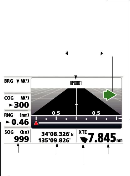
Highway Display
The highway display provides a 3-D view of own boat’s progress toward destination.
XTE (Cross-track error) scale and arrow mark Arrow shifts with boat’s XTE. When the arrow is aligned with the center line the boat is on course. The arrow blinks if boat’s XTE is greater than XTE scale range.
“N (North)” is displayed, instead of the arrow, at the center of the scale when no destination is set.
|
|
|
Direction to steer |
||
Bearing from |
|
|
(to return to course) |
||
|
|
: Steer right. |
|
: Steer left. |
|
|
|
|
|||
own boat to |
Destination |
||||
destination |
|||||
waypoint |
waypoint name |
||||
|
|
|
|
|
|
|
|
|
|
|
|
|
|
|
|
|
|
|
|
|
|
|
|
|
|
|
|
|
|
|
|
|
|
299 |
|
|
|
|
|
|
|
|
|||||
Course |
|
|
|
|
|
|
|
|
|
|
|
|
|
|
|
|
|
|
|
166 |
|
|
|
|
|
|
|
|
|||
over |
|
|
|
|
|
|
|
|
|
|
|
|
|||
|
|
|
|
|
|
|
|
|
|||||||
ground |
|
|
|
|
|
|
|
|
|
|
|
|
|
|
|
|
|
|
|
|
|
|
|
|
|
|
|
|
|
||
|
|
|
|
|
0.46 |
|
|
|
|
|
|
|
|||
|
|
|
|
|
|
|
|
|
|
|
|
||||
|
|
|
|
|
|
|
|
|
|
|
|
|
|
|
|
|
|
|
|
|
|
|
|
|
|
|
N |
|
|
|
|
|
|
|
|
|
|
14.6 |
|
|
|||||||
|
|
|
|
|
|
|
|
|
E |
|
|
|
|||
|
|
|
|
|
|
|
|
|
|
|
|
|
|
|
|
Speed |
Current |
|
over |
||
position |
||
ground |
Range from own boat to destination waypoint
Digital XTE indication (in nautical miles)
Own boat mark
The boat mark displays course as follows: When no waypoint is set;
The mode is North-up and
the arrow shows boat’s course. When a waypoint is set;
The arrow shows boat’s course towards destination.
1-5
1. OPERATIONAL OVERVIEW
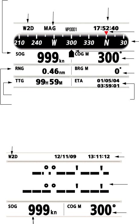
Steering Display
The steering display provides steering information.
Speed |
|
|
|
|
|
over ground |
Bearing reference; |
Time |
|||
|
|
||||
Receiver status |
MAG(netic) or TRUE |
|
|
||
|
|
||||
|
|
|
|
||
|
|
|
|
|
|
|
|
|
|
|
|
|
|
|
|
|
|
|
|
|
|
|
|
|
|
|
|
|
|
|
|
|
|
|
|
Bearing destination |
|
|
|
|
|
|
|
|
|
|
|
|
|
|
|
|
|
|
|
||
|
|
|
|
|
|
|
|
|
|
|
|
|
|
|
|
|
|
|
Bearing scale |
|
|
|
|
|
|
|
|
|
|
|
|
|
|
|
|
|
|
|
|
|
|
|
|
|
|
|
|
|
|
|
|
|
|
|
|
|
|
Own boat mark |
|
|
|
14.6 |
|
|
|
|
300 |
|
|
|
|
|
|||||||
|
|
|
|
|
|
|
|
|
|
|
Course over ground |
||||||||
|
|
|
|
|
|
|
|
|
|
|
|
|
|
|
|
|
|
||
|
|
|
|
|
|
|
|
|
|
|
|
|
|
|
|
|
|
|
|
|
|
|
|
|
|
|
|
|
|
|
|
|
|
|
|
|
|
|
|
0.46 |
|
|
|
|
|
|
|
|
|
|
|
||||||||
|
|
|
|
|
|
|
299 |
|
|
|
|
|
Bearing to |
||||||
|
|
|
|
|
|
|
|
|
|
|
|
|
|||||||
|
|
|
|
|
|
|
|
|
|
|
|
|
|
|
|
|
|
the destination |
|
|
|
|
|
|
|
|
|
|
|
|
|
|
|
|
|
|
|||
|
00 |
|
15 |
|
|
|
|
17:57:40 |
|
|
|
|
|
|
|||||
|
|
|
|
|
|
|
|
|
|
12/11/09 |
|
|
|
|
|
|
|||
|
|
|
|
|
|
|
|
|
|
|
|
|
|
|
|
|
|
|
|
|
|
|
|
|
|
|
|
|
|
|
|
|
|
|
|
|
|
|
|
|
|
|
|
|
|
|
|
|
|
|
|
|
|
|
|
|
|
|
|
Time-To-Go
to destination
Estimated Time of Range from Arrival at destination own boat to
destination
Nav Data Display
Receiver status
|
|
|
|
|
|
|
|
|
|
|
|
Date and time |
||
|
|
|
|
|
|
|
|
|
|
|
|
|||
|
|
|
|
|
|
|
|
|
|
|
|
|||
|
|
|
|
|
|
|
|
|
|
|
|
|||
34 |
44.589 N |
|
|
|
Position in latitude |
|||||||||
|
|
|
|
|
|
|
|
|
||||||
|
|
135 |
21.074 E |
|
|
|
|
|
|
|
and longitude |
|||
|
|
|
|
|
|
|
|
|
|
|
|
|
|
|
|
|
|
|
|
|
|
|
|
|
|
|
|
|
|
|
|
|
|
|
|
|
|
|
|
|
|
|
|
|
|
|
|
14.6 |
|
300 |
|
|
|
|
|
Course over ground |
|||
|
|
|
|
|
|
|
|
|
||||||
|
|
|
|
|
|
|
|
|
|
|
|
|
|
|
Speed over ground
1-6
1. OPERATIONAL OVERVIEW
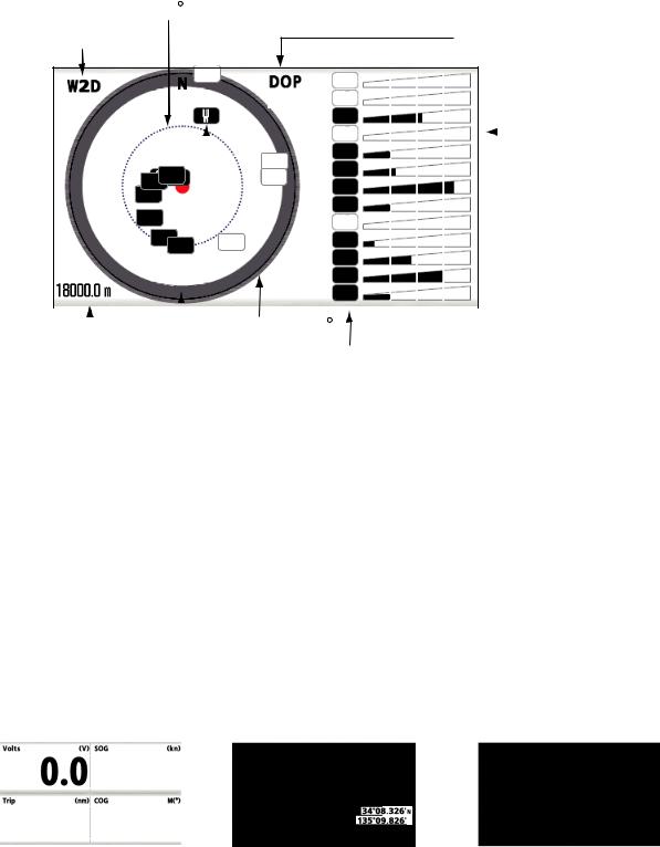
Satellite Monitor Display
The satellite monitor display shows the condition of GPS and GEO (WAAS) satellites. Number, bearing and elevation angle of all GPS and GEO satellites (if applicable) in view of your receiver appear.
|
Elevation |
|
Receiver |
45 |
|
DOP value |
||
status |
11 |
02 |
|
1.6005
|
|
|
|
|
|
|
|
|
|
|
08 |
|
|
Receiver |
|
|
|
|
|
|
|
|
|
|
|
|
11 |
|
|
||
|
|
|
|
|
|
|
|
|
|
|
|
|
|||
|
|
|
|
|
|
|
|
|
|
|
13 |
|
|
signal level |
|
|
|
|
|
GEO satellite |
|
05 |
|
|
|||||||
|
|
|
|
2208 |
|
|
|
|
15 |
|
|
Bars show |
|||
|
|
|
|
|
|
|
|
|
|
|
|
||||
|
|
|
|
|
|
|
02 |
|
|
||||||
|
|
|
|
|
|
|
17 |
|
|
signal level. |
|||||
|
|
|
|
13 |
|
|
|
|
|
|
22 |
|
|
Satellites |
|
|
|
|
|
17 |
|
|
|
|
|
|
|
|
|||
|
|
|
|
|
|
|
|
|
|
25 |
|
|
whose signal |
||
|
|
|
|
3230 |
25 |
|
|
|
|
28 |
|
|
level are high |
||
|
|
|
|
|
|
|
|
|
|
|
30 |
|
|
are used in |
|
|
|
|
|
|
|
|
|
|
|
|
32 |
|
|
fixing position. |
|
|
12.0 |
|
|
|
|
|
|
|
|
133 |
|
|
|
||
|
|
|
|
|
|
|
|
|
|
|
|
||||
|
|
|
|
|
|
|
|
|
|
|
|
|
|
|
|
|
|
|
|
|
|
|
|
|
|
|
|
|
|
|
|
|
|
|
|
|
|
Elevation 5 |
|
|
|
|
|
||||
|
Altitude |
|
|
|
|
|
|
|
|
|
|
|
|
||
|
|
|
|
|
|
|
|
Satellite numbers in |
|
||||||
|
Area not used |
|
|
|
|
||||||||||
|
|
|
|
for positioning |
|
|
|
reverse video are |
|
||||||
|
|
|
|
(set at menu) |
|
|
|
used for positioning. |
|
||||||
|
|
|
|
|
|
|
|
|
|
|
|
||||
User Display 1, User Display 2
•Digital display
The digital display shows digital navigation data. You can select what data to display in one to four cells. The choices of data are time, date, speed over ground, cross-track-error, odometer distance, position, course over ground, time-to-go to destination, trip distance, power source voltage, range and bearing to waypoint and estimated time of arrival at destination.
•Speedometer display
The speedometer display provides both digital and analog displays of speed over ground.
•COG display
The COG display shows both analog course over ground, and digital speed over ground.
|
|
15.8 |
|
|
|
|
|
|
|
|
|
|
|
|
|
23.9 |
|
|
|
|
|
|
|
|
|
|
|
|
|
55.7 |
335 |
|
|
|
|
|
|
|
|
|
|
|
|
|
|
|
|
|
|
N |
|
|
|
|
|
||||
|
40.0 |
|
|
|
|
|
|
40.0 |
|
|||||
|
E |
|
||||||||||||
|
|
|
|
|
|
|
|
|
|
|
|
|
||
|
|
|
|
|
|
|
|
|
|
|
|
|
|
|
|
|
|
|
|
|
|
|
|
|
|
|
|
|
|
Digital display (four cells) |
Speedometer display |
|
COG display |
|||||||||||
|
|
|
|
(default: User display 1) |
(default: User display 2) |
|||||||||
1-7
1. OPERATIONAL OVERVIEW
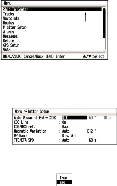
1.5Menu Overview
Most operations of your unit are done through the menu. Below is a quick introduction to how to select a menu and change menu settings. If you get lost in operation, press the MENU/ZOOM key to return to the main menu.
1.Press the MENU/ZOOM key once or twice to display the main menu.
Press once: Steering display, nav data display, satellite monitor display, user display 1/2.
Press twice: Plotter display, highway display
Note: Following explanation takes the menus for the plotter display as an example.
*
Cursor
*: Shown only when the MENU/ZOOM key is pressed at the plotter display.
2.Press S or T to select an item, and press the ENT key.
3.Press ENT (or X) key.
For example, select [Plotter Setup] and press the ENT key.
4.Press S or T to select option desired. For example, select [COG/BRG ref.]
5.Press the ENT key (or X).
A window shows the options for the item selected.
6.Press S or T to select option desired.
7.Press the ENT key (or X).
8.Press the MENU/ZOOM key (or W) twice to close the menu.
1-8
1. OPERATIONAL OVERVIEW
How to enter alphanumeric data
Some menu operations require you to enter alphanumeric data (A to Z, 0 to 9) and symbols (&, _, #,’ , -, > and space). The procedure which follows shows how to enter alphanumeric data. For example, to change the waypoint name “WP0006” to “KOBE”, do the follows:
Cursor 

1)Press S or T to select “K”.
2)Press X, and press S or T to select “O”.
3)Press X, and press S or T to select “B”.
4)Press X, and press S or T to select “E”.
5)Press X, and press S or T to select “ “(space).
6)Press X, and press S or T to select “ ” (space).
7)Press the ENT key.
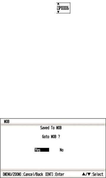
1.6How to Enter the MOB Mark
The MOB mark denotes man overboard position. Only one MOB mark is displayed. Each time the MOB mark is entered the previous MOB mark and its position data are overwritten.
1. Press and hold the WPT/MOB key down to show the following message.
2.To set MOB position as destination, confirm that [Yes] is chosen and press the ENT key. MOB mark (“M”) appears and a blue line is drawn between own boat mark and the MOB mark. This line shows the shortest course to go to the MOB position, and arrows on the line show the direction to the MOB position.
1-9

1. OPERATIONAL OVERVIEW
Shortest course from own |
MOB mark |
boat to MOB position (blue) |
(red) |
|
|
N 34 08.500 |
0.20 |
|
N 34 08.375 |
|
|
|
95 |
E 135 09.750 |
E 135 10.000 |
Bearing from own boat to MOB position
Range from own boat to MOB position
1-10
2.PLOTTER DISPLAY OVERVIEW
2.1How to Select the Display Range
You can change the display range on the plotter and highway displays. The horizontal range in the plotter display is available among 0.02, 0.05, 0.1, 0.2, 0.5, 1, 2, 5, 10, 20, 40, 80, 160 and 320 nautical miles. The horizontal range in the highway display is available among 0.2, 0.4, 0.8, 1, 2, 4, 8 and 16 nautical miles.
1.Press the MENU/ZOOM key on the plotter or highway display. The following window appears.
(Plotter display) (Highway display)
2.Press S or T to select range you want.
3.Press the ENT key.
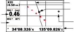
2.2How to Shift the Cursor
Use the cursorpad to shift the cursor. The cursor moves in the direction of the arrow or diagonal.
Cursor state and position indication
The position indication, shown at bottom of the plotter display, changes according to cursor state.
Cursor at rest
When the cursor is not shown, boat’s position in longitude and latitude or TDs (depending on the menu setting) appears at the bottom of the display.
COG (course over ground)
SOG (speed over ground)
 20.0
20.0
 350
350
COG line

 Own boat
Own boat’s position
 in latitude and longitude
2-1
2. PLOTTER DISPLAY OVERVIEW
Cursor state and position indication
Cursor position is displayed in latitude and longitude or TDs at the bottom of the plotter display when the cursor is shown.
If there is no operation for about seven seconds, the cursor disappears.
Range from own boat to cursor
Bearing from own boat to cursor
|
COG line |
|
Own boat’s mark |
92 |
Cursor |
|
Cursor position in |
|
latitude and longitude |
2.3How to Shift the Display
The display can be shifted on the plotter display.
1.Press the cursorpad to show the cursor.
2.Press and hold down an arrow on the cursorpad.
When the cursor is placed at an edge of the screen, the display shifts in the direction opposite to cursorpad operation.
Centering own boat’s position
When own boat tracks off the plotter display, the own boat mark is automatically returned to the screen center. You can also return it manually by pressing and holding the ENT key for more than three seconds.
2-2
2. PLOTTER DISPLAY OVERVIEW
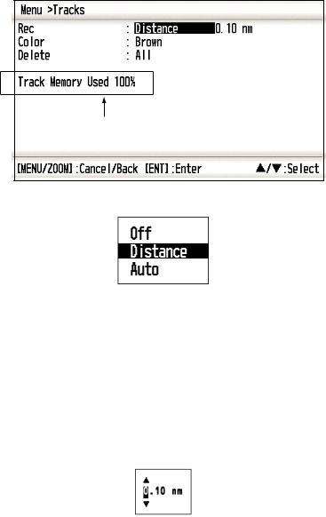
2.4How to Change Track Plotting Interval, Stop Recording
To trace the boat’s track, the boat’s position is stored into the memory at an interval of distance or according to display range. For distance, a shorter interval provides better reconstruction of the track, but the storage time of the track is shorten. When the track memory becomes full, the oldest track is erased to make room for the latest. The current percentage of the memory used can be confirmed by choosing [Tracks] on the menu.
1.Press the MENU/ZOOM key twice to show the main menu.
2.Select [Tracks], and press the ENT key.
Percentage of the memory used
3.Confirm that the [Rec] is selected, and press the ENT key.
4.Select [Off], [Distance] or [Auto], and press the ENT key.
Off: Track is not recorded. This setting is useful when you do not need to record track.
Distance: Track is recorded and plotted at the distance interval set.
Auto: Plotting and recording interval changes with display range selected.
5.For [Off] or [Auto], go to step 6. For [Distance], enter the recording interval as follows:
1)Press X.
2)Press ENT key.
3)Use the cursorpad to enter the interval, and press the ENT key. For entering the numeric data, see page 1-9.
6.Press the MENU/ZOOM key twice to close the menu.
2-3
2. PLOTTER DISPLAY OVERVIEW
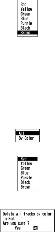
2.5How to Change Track Color
You can select the color for the tracks among red, yellow, green, blue, purple, black and brown. It is useful to change the color to distinguish tracks at different times of a day, for example.
1.Press the MENU/ZOOM key twice to show the main menu.
2.Select [Tracks], and press the ENT key.
3.Select [Color], and press the ENT key.
4.Select the color to use for the track, and press the ENT key.
5.Press the MENU/ZOOM key twice to close the menu.
2.6How to Erase Track
The tracks can be erased collectively or by color. The tracks cannot be restored once erased, therefore be absolutely sure you want to erase the tracks.
2.6.1How to erase track by color
1.Press the MENU/ZOOM key twice to show the main menu.
2.Select [Tracks], and press the ENT key.
3.Select [Delete], and press the ENT key.
4.Select [By Color], and press the ENT key.
5.Select the track color to erase, and press the ENT key. The window shown below appears.
6.Press W to select [Yes], and press the ENT key.
The tracks with the color chosen at step 5 are erased.
2-4

2. PLOTTER DISPLAY OVERVIEW
Note: To cancel, select [No] at this step.
7.Press the MENU/ZOOM key twice to close the menu.
2.6.2How to erase all tracks
1.Press the MENU/ZOOM key twice to show the main menu.
2.Select [Tracks], and press the ENT key.
3.Select [Delete], and press the ENT key.
4.Select [All], and press the ENT key.
5.Press W to select [Yes], and press the ENT key to erase all tracks. [Track Memory Used] on the Tracks menu shows “0%”.
6.Press the MENU/ZOOM key twice to close the menu.
2-5
2. PLOTTER DISPLAY OVERVIEW
This page is intentionally left blank.
2-6

3.WAYPOINTS
3.1How to Enter Waypoints
In navigation terminology a waypoint is a particular location on a voyage, whether it be a starting, intermediate or destination waypoint. Your unit can store 10,000 waypoints. Waypoints can be entered on the plotter display: at cursor position, at own boat’s position, through the waypoints list and at the MOB position. Also, waypoints can be entered automatically when your boat changes course prominently.
3.1.1How to enter a waypoint with the cursor
1.Use the cursorpad to place the cursor on the location desired for a waypoint.
2.Press the ENT key to enter the waypoint mark (default shape: green solid circle). This waypoint is named with the youngest unused waypoint number, and saved to the waypoint list.
3.1.2How to enter a waypoint at own boat position
Press the WPT/MOB key to enter the waypoint mark (default shape: green solid circle). This waypoint is named with the youngest unused waypoint number, and saved to the waypoint list.
3.1.3How to enter a waypoint through the list
1.Press the MENU/ZOOM key to show the main menu.
2.Select [Waypoints], and press the ENT key.
3.Press the ENT key to show the waypoint list.
3-1
3.WAYPOINTS
4.Confirm that [New] is chosen, and press the ENT key.
The default name, Lat/Lon and Comment are as follows: Name: The youngest unused waypoint number.
Lat, Lon: Current own boat position Comment: Current date/time
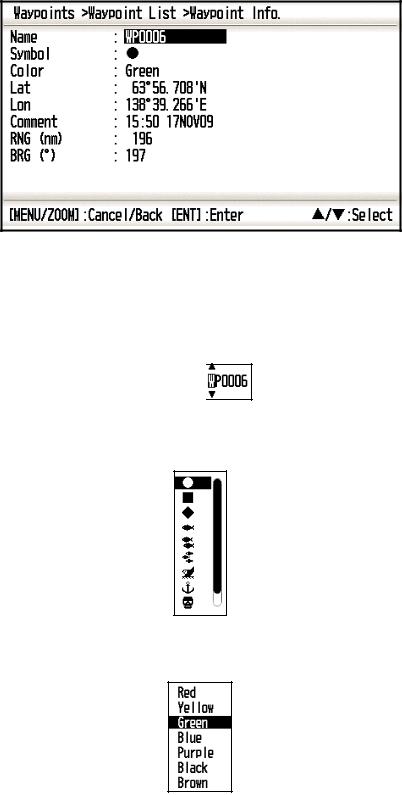
5. To change the waypoint name, press the ENT key.
Cursor 

6.Operate the cursorpad to change the waypoint name (max. 8 characters).
7.To change the mark shape, select [Symbol] and press the ENT key.
8.Select a mark desired, and press the ENT key.
9.To change the mark color, select [Color], and press the ENT key.
10.Select a color desired, and press the ENT key.
11.To change the position, do as follows:
1)Select [Lat], and press the ENT key.
2)Enter latitude, and press the ENT key.
3)Press T to select [Lon], and press the ENT key.
4)Enter longitude, and press the ENT key.
3-2
3. WAYPOINTS
12.To change the comment, select [Comment] and press the ENT key.
13.Enter the comment, and press the ENT key.
14.Press the MENU/ZOOM key to register the new waypoint into the list.
15.To register other waypoints, repeat steps 4 through 14.
16.Press the MENU/ZOOM key several times to close the menu.
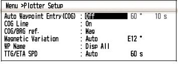
3.1.4How to enter waypoints automatically
Waypoints can be entered automatically when your course changes by a specified degree. This function is useful for reversely following the waypoints recorded on an outward voyage when you return home. To set the criteria for automatic entering of waypoints, do the following:
1.Press the MENU/ZOOM key twice to show the main menu.
2.Select [Plotter Setup], and press the ENT key.
3.Select [Auto Waypoint Entry (COG)], and press the ENT key.
4.Select [On], and press the ENT key.
5.Press X to select the degree setting, and press the ENT key.
6.Enter the degree, and press the ENT key (setting range: 15 to 150°).
7.Press X to select the seconds setting, and press the ENT key.
8.Enter the seconds, and press the ENT key (setting range: 1 to 60 seconds).
9.Press the MENU/ZOOM key twice to close the menu.
3-3
3. WAYPOINTS
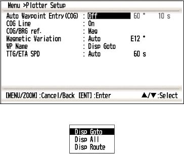
3.2How to Display Waypoint Name
You can display waypoint names as follows:
1.Press the MENU/ZOOM key twice to show the main menu.
2.Select [Plotter Setup], and press the ENT key.
3.Select [WP Name], and press the ENT key.
4.Select [Disp Goto], [Disp All] or [Disp Route], and press the ENT key. Disp Goto: Displays only the destination waypoint name.
Disp All: Displays all waypoint names.
Disp Route: Displays all waypoint names in the route when it is set as destination.
5.Press the MENU/ZOOM key twice to close the menu.
3-4
 Loading...