


 Loading...
ZXSDR R8978
TDD 8 Path Remote Radio Unit
User Manual
Version: V5.10
ZTE CORPORATION
No. 55, Hi-tech Road South, ShenZhen, P.R.China Postcode: 518057
Tel: +86-755-26771900
Fax: +86-755-26770801 URL: http://support.zte.com.cn E-mail: 800@zte.com.cn

LEGAL INFORMATION
Copyright © 2017 ZTE CORPORATION.
The contents of this document are protected by copyright laws and international treaties. Any reproduction or distribution of this document or any portion of this document, in any form by any means, without the prior written consent of ZTE CORPORATION is prohibited. Additionally, the contents of this document are protected by contractual confidentiality obligations.
All company, brand and product names are trade or service marks, or registered trade or service marks, of ZTE CORPORATION or of their respective owners.
This document is provided “as is”, and all express, implied, or statutory warranties, representations or conditions are disclaimed, including without limitation any implied warranty of merchantability, fitness for a particular purpose, title or non-infringement. ZTE CORPORATION and its licensors shall not be liable for damages resulting from the use of or reliance on the information contained herein.
ZTE CORPORATION or its licensors may have current or pending intellectual property rights or applications covering the subject matter of this document. Except as expressly provided in any written license between ZTE CORPORATION and its licensee, the user of this document shall not acquire any license to the subject matter herein.
ZTE CORPORATION reserves the right to upgrade or make technical change to this product without further notice. Users may visit the ZTE technical support website http://support.zte.com.cn to inquire for related information.
The ultimate right to interpret this product resides in ZTE CORPORATION.
Revision History
Revision Version |
Revision Date |
Revision Reason |
|
|
|
R1.2 |
2016–08–17 |
Added S2600L |
|
|
|
R1.1 |
2014-10-30 |
Added S2600M |
|
|
|
R1.0 |
2014-08-06 |
First edition |
|
|
|
Serial Number: SJ-20141113151137-001
Publishing Date: 2016-08-17 (R1.2)
SJ-20141113151137-001|2016-08-17 (R1.2) |
ZTE Proprietary and Confidential |

Contents
About This Manual ......................................................................................... |
I |
|||
Chapter 1 FCC Related Statements .......................................................... |
1-1 |
|||
Chapter 2 Product Overview ..................................................................... |
2-1 |
|||
2.1 |
Product Positioning ............................................................................................ |
2-1 |
||
2.2 |
Product Features................................................................................................ |
2-2 |
||
2.3 |
External View..................................................................................................... |
2-2 |
||
2.4 |
Product Specifications ........................................................................................ |
2-3 |
||
|
2.4.1 ZXSDR R8978 S2300............................................................................... |
2-3 |
||
|
2.4.2 ZXSDR R8978 S2600M............................................................................ |
2-4 |
||
|
2.4.3 ZXSDR R8978 S2600L............................................................................. |
2-4 |
||
2.5 |
External Interfaces ............................................................................................. |
2-5 |
||
2.6 |
Installation Modes .............................................................................................. |
2-6 |
||
2.7 |
Typical Networking Applications .......................................................................... |
2-6 |
||
Chapter 3 Product Composition ............................................................... |
3-1 |
|||
3.1 |
System Structure................................................................................................ |
3-1 |
||
3.2 |
Composition....................................................................................................... |
3-2 |
||
3.3 |
LED Indicators ................................................................................................... |
3-3 |
||
3.4 |
Physical Interfaces and Cables ........................................................................... |
3-5 |
||
|
3.4.1 Protective Grounding Cable ...................................................................... |
3-5 |
||
|
3.4.2 DC Power Input Cable.............................................................................. |
3-6 |
||
|
3.4.3 LMT/TST Interface Cable.......................................................................... |
3-9 |
||
|
3.4.4 Optical Fiber .......................................................................................... |
3-10 |
||
|
3.4.5 Antenna Feeder Interface Cable............................................................... |
3-11 |
||
|
3.4.6 CAL/AISG Interface Cable ...................................................................... |
3-13 |
||
|
3.4.7 EAM/RGPS Interface Cable.................................................................... |
3-14 |
||
3.5 |
External Cable Connection ............................................................................... |
3-14 |
||
3.6 |
Software Composition....................................................................................... |
3-15 |
||
Chapter 4 Operation and Maintenance..................................................... |
4-1 |
|||
4.1 |
Technical Support............................................................................................... |
4-1 |
||
4.2 |
Fault Location .................................................................................................... |
4-2 |
||
4.3 |
Equipment Maintenance ..................................................................................... |
4-3 |
||
4.4 |
Power On .......................................................................................................... |
4-4 |
||
4.5 |
Power Off .......................................................................................................... |
4-5 |
||
|
|
|
|
|
|
|
I |
|
|
SJ-20141113151137-001|2016-08-17 (R1.2) |
ZTE Proprietary and Confidential |
|||

4.6 Parts Replacement............................................................................................. |
4-6 |
4.6.1 Replacing the ZXSDR R8978.................................................................... |
4-6 |
4.6.2 Replacing the Optical Module.................................................................... |
4-7 |
4.6.3 Replacing the RF Cable............................................................................ |
4-8 |
Chapter 5 Accessory Devices ................................................................... |
5-1 |
|
5.1 |
Junction Box ...................................................................................................... |
5-1 |
5.2 |
AC Power Lightening Protection Box ................................................................... |
5-3 |
5.3 |
Replacing the AC Power Lighting Protection Box.................................................. |
5-6 |
Chapter 6 Technical Specifications .......................................................... |
6-1 |
|
6.1 |
Physical Specifications ....................................................................................... |
6-1 |
6.2 |
Performance Indexes ......................................................................................... |
6-1 |
6.3 |
Power Consumption ........................................................................................... |
6-2 |
6.4 |
Reliability Indexes .............................................................................................. |
6-2 |
6.5 |
Grounding Requirement...................................................................................... |
6-3 |
6.6 |
Lightening and Surge Protection ......................................................................... |
6-3 |
Chapter 7 Environment Requirements..................................................... |
7-1 |
|
7.1 |
Power Supply Requirements............................................................................... |
7-1 |
7.2 |
Operating Environment....................................................................................... |
7-1 |
7.3 |
Storage Environment.......................................................................................... |
7-2 |
Figures............................................................................................................. |
I |
|
Tables ............................................................................................................ |
III |
|
Glossary ......................................................................................................... |
V |
|
II
SJ-20141113151137-001|2016-08-17 (R1.2) |
ZTE Proprietary and Confidential |

About This Manual
Purpose
This manual describes the software and hardware structures, interfaces and cables, functions, features, technical specifications, installation modes, networking, and maintenance methods of the ZXSDR R8978.
Intended Audience
This manual is intended for:
•Base station installation engineers
•Base station commissioning engineers
•Base station maintenance engineers
What Is in This Manual
This manual contains the following chapters.
Chapter 1, FCC Related |
Describes the statements related to FCC rule. |
Statements |
|
|
|
Chapter 2, Product Overview |
Describes the external view, interfaces, functions, features, and |
|
typical network applications of the ZXSDR R8978. |
|
|
Chapter 3, Product Composition |
Describes the system structure, hardware composition, and |
|
software composition of the ZXSDR R8978. |
|
|
Chapter 4, Operation and |
Provides the technical support contact information, power-on and |
Maintenance |
power-off flow, and component replacement methods. |
|
|
Chapter 5, Accessory Devices |
Describes the accessory devices, including junction box, and AC |
|
power lightening protection box, and the replacement methods. |
|
|
Chapter 6, Technical |
Provides the technical specifications of the ZXSDR R8978. |
Specifications |
|
|
|
Chapter 7, Environment |
Describes the environment requirements of the ZXSDR R8978. |
Requirements |
|
|
|
Conventions
This manual uses the following conventions.
Danger: indicates an imminently hazardous situation. Failure to comply can result in death or serious injury, equipment damage, or site breakdown.
Warning: indicates a potentially hazardous situation. Failure to comply can result in serious injury, equipment damage, or interruption of major services.
I
SJ-20141113151137-001|2016-08-17 (R1.2) |
ZTE Proprietary and Confidential |

Caution: indicates a potentially hazardous situation. Failure to comply can result in moderate injury, equipment damage, or interruption of minor services.
Note: provides additional information about a topic.
II
SJ-20141113151137-001|2016-08-17 (R1.2) |
ZTE Proprietary and Confidential |

Chapter 1
FCC Related Statements
 Warning!
Changes or modifications to this unit not expressly approved by the party responsible for compliance could void the user’s authority to operate the equipment.
This equipment has been tested and found to comply with the limits for a Class A digital device, pursuant to Part 15 of the FCC Rules. These limits are designed to provide reasonable protection against harmful interference when the equipment is operated in a commercial environment. This equipment generates, uses, and can radiate radio frequency energy and, if not installed and used in accordance with the instruction manual, may cause harmful interference to radio communications. Operation of this equipment in a residential area is likely to cause harmful interference in which case the user will be required to correct the interference at his own expense.
Operation of this equipment in a residential area is likely to cause harmful interference in which case the user will be required to correct the interference at his own expense.
This equipment complies with FCC radiation exposure limits set forth for an uncontrolled environment. This equipment should be installed and operated with minimum distance 10.2 m between the radiator & your body.
1-1
SJ-20141113151137-001|2016-08-17 (R1.2) |
ZTE Proprietary and Confidential |

ZXSDR R8978 User Manual
This page intentionally left blank.
1-2
SJ-20141113151137-001|2016-08-17 (R1.2) |
ZTE Proprietary and Confidential |

Chapter 2
Product Overview
Table of Contents
Product Positioning .................................................................................................... |
2-1 |
Product Features........................................................................................................ |
2-2 |
External View ............................................................................................................. |
2-2 |
Product Specifications................................................................................................ |
2-3 |
External Interfaces ..................................................................................................... |
2-5 |
Installation Modes ...................................................................................................... |
2-6 |
Typical Networking Applications ................................................................................. |
2-6 |
2.1 Product Positioning
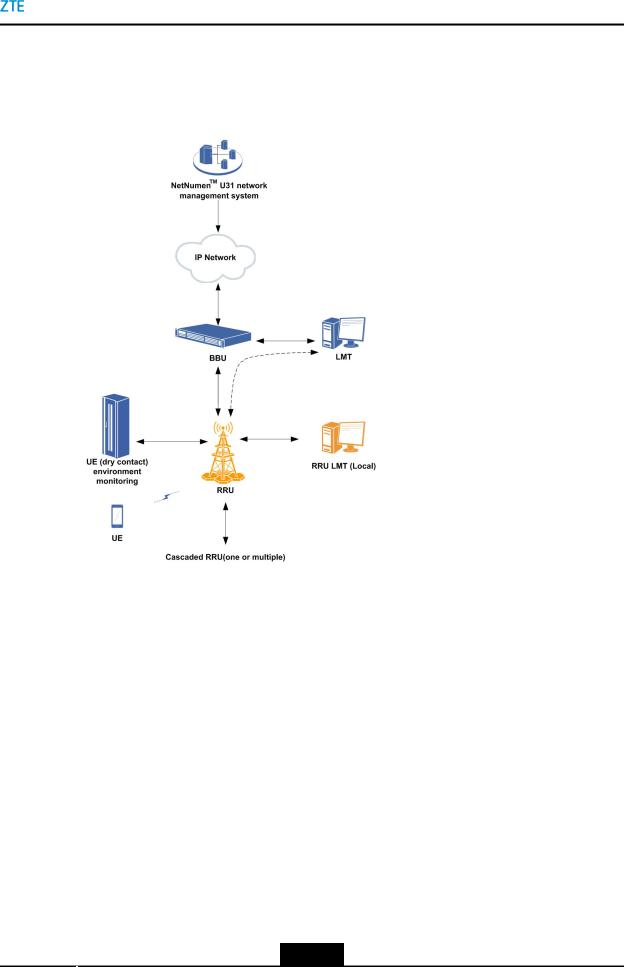
The ZXSDR R8978 is an eight-path TD-LTERRU with high power. It operates with a BBU to cover new outdoor sites.
The ZXSDR R8978 works with a BBU to compose a complete eNodeB and implement the functions such as radio transmission in the coverage area and radio channel control.
Figure 2-1 illustrates the position of the ZXSDR R8978 in a LTE network.
Figure 2-1 Position of the RRU in a Network
2-1
SJ-20141113151137-001|2016-08-17 (R1.2) |
ZTE Proprietary and Confidential |

ZXSDR R8978 User Manual
2.2 Product Features
Unified Platform
The ZXSDR R8978 is developed based on the unified SDR platform, which supports smooth evolution to new technologies in the future, and protects the operators' investment in maximum.
Energy conservation and environmental protection
•Designed with high-efficiency power amplifier technologies: Crest Factor Reduction (CFR), Digital Pre-Distortion (DPD) and Doherty to reduce equipment's power consumption.
•Uses passive heat dissipation without electrical noise, which can save 35% power consumption compared with the traditional air conditioner to effectively reduce the operators' power consumption cost.
•Supports the energy-saving technologies such as slot-based power saving and voltage regulation power saving.
Multi-Carrier, MIMO, BF, and High Performance
•Supports multiple frequency bands such as 2.3 GHz/2.6 GHz to satisfy the requirements of various operators.
•Supports flexible configuration of up to TD-LTE 4x20 MHz multi-carriers to fully and flexibly utilize the operators' spectrum.
High Output Power
Up to 160 W (8x20 W) output power is provided to satisfy the power requirements for high capacity and large coverage.
10 Gbps Optical Interface
Two 10 Gbps CPRI optical interfaces are provided to satisfy the TD-LTE CPRI flow requirement. CPRI optical interface multi-mode transmission is supported (the 6 Gbps optical interface rate is also supported).
2.3 External View
Figure 2-2 shows the external view of the ZXSDR R8978.
2-2
SJ-20141113151137-001|2016-08-17 (R1.2) |
ZTE Proprietary and Confidential |
Chapter 2 Product Overview
Figure 2-2 External View
2.4 Product Specifications
The ZXSDR R8978 is an eight-channel RRU that an be used for networking TD-LTE macro cells.
In this manual, all the descriptions for the ZXSDR R8978 are applicable to the following specifications unless specially stated:
•ZXSDR R8978 S2300
•ZXSDR R8978 S2600M
•ZXSDR R8978 S2600L
2.4.1ZXSDR R8978 S2300
For the key features of the ZXSDR R8978 S2300, refer to Table 2-1.
Table 2-1 Key Features of the ZXSDR R8978 S2300
|
Item |
|
Description |
||
|
Radio access mode |
|
TD-LTE |
||
|
|
|
|
|
|
|
Frequency band |
|
2300 MHz~2400 MHz |
||
|
|
|
|
|
|
|
Antenna |
|
Supports 4×4 MIMO dual TRX channels. |
||
|
|
|
|
|
|
|
Maximum number of carriers |
|
TD-LTE: 4×20 MHz |
||
|
|
|
|
|
|
|
|
|
|
|
|
|
|
|
2-3 |
|
|
SJ-20141113151137-001|2016-08-17 (R1.2) |
|
|
ZTE Proprietary and Confidential |
||

ZXSDR R8978 User Manual
Item |
Description |
|
|
|
|
Signal bandwidth |
80 |
MHz |
|
|
|
Maximum power output in each channel |
20 |
W |
|
|
|
Power input |
DC: -48 V DC |
|
|
AC: 100 V AC/110 V AC/220 V AC |
|
|
|
|
2.4.2 ZXSDR R8978 S2600M
For the key features of the ZXSDR R8978 S2600M, refer to Table 2-2.
Table 2-2 Key Features of the ZXSDR R8978 S2600M
Item |
Description |
|
|
Radio access mode |
TD-LTE |
|
|
Frequency band |
2496 MHz~2690 MHz |
|
|
Antenna |
Smart Antenna |
|
RET |
|
8–path transceiving channels |
|
|
Maximum number of carriers |
TD-LTE: 4x20 MHz 2x20 MHz |
|
|
Signal bandwidth |
100 MHz |
|
|
Maximum power output in each channel |
20 W |
|
|
Power input |
-48 VDC |
|
|
2.4.3 ZXSDR R8978 S2600L
For the key features of the ZXSDR R8978 S2600L, refer to Table 2-3.
Table 2-3 Key Features of the ZXSDR R8978 S2600L
|
Item |
|
Description |
||
|
Radio access mode |
|
TD-LTE |
||
|
|
|
|
|
|
|
Frequency band |
|
2575 MHz~2635 MHz |
||
|
|
|
|
|
|
|
Antenna |
|
Smart Antenna |
||
|
|
|
|
RET |
|
|
|
|
|
8–path transceiving channels |
|
|
|
|
|
|
|
|
Maximum number of carriers |
|
TD-LTE: 3x20 MHz |
||
|
|
|
|
|
|
|
Signal bandwidth |
|
60 MHz |
||
|
|
|
|
|
|
|
Maximum power output in each channel |
|
20 W |
||
|
|
|
|
|
|
|
Power input |
|
-48 VDC |
||
|
|
|
|
|
|
|
|
|
|
|
|
|
|
|
2-4 |
|
|
SJ-20141113151137-001|2016-08-17 (R1.2) |
|
|
ZTE Proprietary and Confidential |
||
Chapter 2 Product Overview
2.5 External Interfaces
Figure 2-3 illustrates the external interfaces of the ZXSDR R8978.
Figure 2-3 External Interfaces
For a description of the external interfaces, refer to Table 2-4.
Table 2-4 External Interface Description
External Device |
Description |
External Interface |
|
|
|
BBU |
BBU performs the functions such as GPS |
Logical interface: Ir interface |
|
synchronization, main control, and baseband |
Physical interface: optical |
|
processing. |
fiber interface |
|
|
|
UE |
UE accomplishes the Uu interface functions of |
Logical interface: Uu interface |
|
transmitting voice and data services. |
Physical interface: none |
|
|
|
User device |
External environment monitoring device |
Logical interface: not |
|
|
standardized |
|
|
Physical interface: dry contact |
|
|
|
2-5
SJ-20141113151137-001|2016-08-17 (R1.2) |
ZTE Proprietary and Confidential |

ZXSDR R8978 User Manual
External Device |
Description |
External Interface |
|
|
|
RRULMT |
Operates and maintains the RRU at the local |
Logical interface: not |
|
end |
standardized |
|
|
Physical interface: Ethernet |
|
|
interface |
|
|
|
Cascade RRU |
Upstream RRU |
Logical interface: Ir interface |
|
|
Physical interface: optical |
|
|
fiber interface |
|
|
|
•External interfaces exclude the power and antenna interface of the RRU.
 Note:
Note:
The LMT at the BBU side can operate and maintain multiple RRUs under the BBU. ZTE NetNumen™ EMS provides unified operation and maintenance on multiple sites.
2.6 Installation Modes
The ZXSDR R8978 supports three installation modes:
•A single RRU mounted on a pole
•Two RRUs mounted on a pole
•Mounted on a wall
•Mounted on slot steel
•Mounted on angle steel
2.7Typical Networking Applications
The ZXSDR R8978 supports the following networking solutions:
•Chain networking
Chain networking applies to strip-shaped areas with sparse population, where optical fibers can be laid conveniently. Figure 2-4 shows a chain networking solution.
Figure 2-4 Chain Networking
•Star networking
In a star networking solution, a BBU is connected to each RRU and the RRU is the terminal equipment. This networking type is simple and easy for maintenance
2-6
SJ-20141113151137-001|2016-08-17 (R1.2) |
ZTE Proprietary and Confidential |

Chapter 2 Product Overview
and engineering. Because the signal passes through fewer intermediate links along the transmission path, the link reliability is much higher. Figure 2-5 shows a star networking solution.
Figure 2-5 Star Networking
2-7
SJ-20141113151137-001|2016-08-17 (R1.2) |
ZTE Proprietary and Confidential |

ZXSDR R8978 User Manual
This page intentionally left blank.
2-8
SJ-20141113151137-001|2016-08-17 (R1.2) |
ZTE Proprietary and Confidential |

Chapter 3
Product Composition
Table of Contents
System Structure........................................................................................................ |
3-1 |
Composition............................................................................................................... |
3-2 |
LED Indicators............................................................................................................ |
3-3 |
Physical Interfaces and Cables .................................................................................. |
3-5 |
External Cable Connection....................................................................................... |
3-14 |
Software Composition .............................................................................................. |
3-15 |
3.1 System Structure
Figure 3-1 shows the system structure of the ZXSDR R8978.
Figure 3-1 System Structure
Table 3-1 describes the subsystems of the ZXSDR R8978.
Table 3-1 Subsystem Description
|
Name |
Type |
Function |
|||
|
|
|
|
|
|
|
|
RRU software |
Software |
Provides the system operating system and OM functions |
|||
|
subsystem |
subsystem |
|
|
|
|
|
|
|
|
|
|
|
|
Transceiver |
Hardware |
• |
Power interface |
||
|
|
subsystem |
• |
Optical interface |
||
|
|
|
|
• |
Control functions |
|
|
|
|
|
• |
Clock functions |
|
|
|
|
|
• |
DIF |
|
|
|
|
|
• |
TRX |
|
|
|
|
|
|
|
|
|
8T8R filter unit |
Hardware |
Eight-channel filter |
|||
|
|
subsystem |
|
|
|
|
|
|
|
|
|
|
|
|
Structure subsystem |
Structure |
Provides equipment protection, heat dissipation, and |
|||
|
|
subsystem |
installation, and module structure, heat dissipation, and |
|||
|
|
|
|
installation. |
||
|
|
|
|
|
|
|
|
|
|
|
|
|
|
|
|
|
|
3-1 |
|
|
SJ-20141113151137-001|2016-08-17 (R1.2) |
|
|
ZTE Proprietary and Confidential |
|||

ZXSDR R8978 User Manual
3.2 Composition
Figure 3-2 shows the composition of the ZXSDR R8978.
Figure 3-2 Product Composition
1. |
Radiating pin |
4. |
Operation and maintenance |
7. |
Grounding bolt |
2. |
Handle |
|
cavity |
8. |
Breathable valve |
3. |
LED indicators |
5. |
Antenna interface |
9. |
EAM/RGPS interface |
|
|
6. |
CAL/AISG interface |
|
|
•The operation and maintenance cavity contains one DC power interface, two optical interfaces (OPT1 and OPT2), one RRU LMT/test interface (LAM/TST).
•The equipment has six LED indicators.
•A handle is installed on the upper shell to facilitate installation and transportation.
•At the bottom of the equipment, there are eight antenna interfaces (ANT1–ANT8), one hermetic seal (breathable valve), one antenna calibration interface (CAL/AISG), and one dry contract user device interface (EAM/RGPS).
3-2
SJ-20141113151137-001|2016-08-17 (R1.2) |
ZTE Proprietary and Confidential |
Chapter 3 Product Composition
 Note:
Note:
The LMT/TST interface is used for ZTE maintenance personnel to perform commissioning and maintenance.
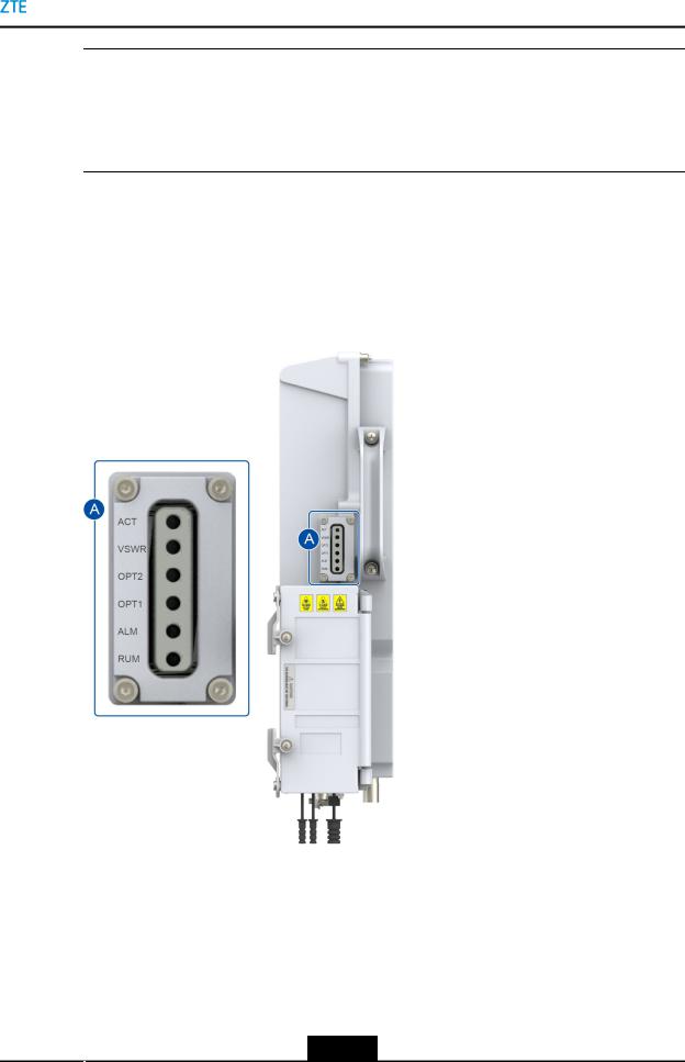
3.3 LED Indicators
An indicator indicates the operating status of a device. Figure 3-3 shows the positions of the indicators.
Figure 3-3 LED Indicators
Table 3-2 describes the LED indicators.
3-3
SJ-20141113151137-001|2016-08-17 (R1.2) |
ZTE Proprietary and Confidential |

ZXSDR R8978 User Manual
Table 3-2 Indicator Descriptions
Name |
Indication |
Color |
Description |
RUN |
Operation |
Green |
OFF: The system is not powered. |
|
indicator |
|
|
|
|
ON: The system is powered. The software system is not |
|
|
|
|
|
|
|
|
running. |
|
|
|
|
|
|
|
Flashing slowly (ON for 1 s and OFF for 1 s): The system is |
|
|
|
powered. The software system is being started. |
|
|
|
|
|
|
|
Flashing normally (ON for 0.3 s and OFF for 0.3 s): The |
|
|
|
system is powered. The software system has been started. |
|
|
|
The communication between the RRU and BBU is normal. |
|
|
|
|
|
|
|
Flashing fast (ON for 70 ms and OFF for 70 ms): The system |
|
|
|
is powered. The software system has been started. The link |
|
|
|
between the ZXSDR R8978 and BBU is not established. |
|
|
|
|
ALM |
Alarm indicator |
Red |
OFF: There is no alarm. |
|
|
|
|
|
|
|
ON: There is an alarm. |
|
|
|
|
OPT1 |
Indicator of |
Green |
OFF: The optical interface does not receive optical signals. |
|
optical interface |
|
|
|
|
ON: The optical interface has received optical signals and |
|
|
1 |
|
|
|
|
the link is not synchronized. |
|
|
|
|
|
|
|
|
|
|
|
|
Flashing (ON for 0.3 s and OFF for 0.3 s): The optical interface |
|
|
|
has received optical signals and the link is synchronized. |
|
|
|
|
OPT2 |
Indicator of |
Green |
OFF: The optical interface does not receive optical signals. |
|
optical interface |
|
|
|
|
ON: The optical interface has received optical signals and |
|
|
2 |
|
|
|
|
the link is not synchronized. |
|
|
|
|
|
|
|
|
|
|
|
|
Flashing (ON for 0.3 s and OFF for 0.3 s): The optical interface |
|
|
|
has received optical signals and the link is synchronized. |
|
|
|
|
VSWR |
Indicator of |
Red |
OFF: VSWRs at all antenna interfaces of the transmitting |
|
the VSWR at |
|
links are normal. |
|
the antenna |
|
|
|
|
ON: There is a VSWR alarm at the antenna interface of the |
|
|
interface |
|
|
|
|
transmitting link. |
|
|
|
|
|
|
|
|
|
ACT |
Radio link |
Green |
Solid ON: Indicates that the radio links are successfully |
|
status indicator |
|
established, and cells are established. |
|
|
|
|
|
|
|
OFF: Indicates that no radio links are established or |
|
|
|
establishment failed, and no cell exists. |
|
|
|
|
•The ALM indicator does not indicate alarms of the optical interfaces (OPT1 and OPT2) and VSWR alarms at the antenna interfaces.
3-4
SJ-20141113151137-001|2016-08-17 (R1.2) |
ZTE Proprietary and Confidential |
Loading...