


 Loading...
V7 PROFIBUS-DP® Option
Technical Manual
Models: CIMR-V7* |
Document Number TM.V7.12 |
|
|
|
|
||
|
|||
|
|
|
|

Warnings and Cautions
This Section provides warnings and cautions pertinent to this product, that if not heeded, may result in personal injury, fatality, or equipment damage. Yaskawa is not responsible for consequences of ignoring these instructions.
 WARNING
YASKAWA manufactures component parts that can be used in a wide variety of industrial applications. The selection and application of YASKAWA products remain the responsibility of the equipment designer or end user. YASKAWA accepts no responsibility for the way its products are incorporated into the final system design. Under no circumstances should any YASKAWA product be incorporated into any product or design as the exclusive or sole safety control. Without exception, all controls should be designed to detect faults dynamically and to fail safely under all circumstances. All products designed to incorporate a component part manufactured by YASKAWA must be supplied to the end user with appropriate warnings and instructions as to that part’s safe use and operation. Any warnings provided by YASKAWA must be promptly provided to the end user. YASKAWA offers an express warranty only as to the quality of its products in conforming to standards and specifications published in the YASKAWA manual. NO OTHER WARRANTY, EXPRESS OR IMPLIED, IS OFFERED. YASKAWA assumes no liability for any personal injury, property damage, losses, or claims arising from misapplication of its products.
 WARNING
Read and understand this manual before installing, operating, or servicing this drive. All warnings, cautions, and instructions must be followed. All activity must be performed by qualified personnel. The drive must be installed according to this manual and local codes.
Do not connect or disconnect wiring while the power is on. Do not remove covers or touch circuit boards while the power is on. Do not remove or insert the digital operator while power is on.
Before servicing, disconnect all power to the equipment. The internal capacitor remains charged even after the power supply is turned off. Status indicator LEDs and Digital Operator display will be extinguished when the DC bus voltage is below 50 VDC. To prevent electric shock, wait at least 5 minutes after all indicators are OFF and measure DC bus voltage and verify that it is at a safe level.
Do not perform a withstand voltage test on any part of the unit. This equipment uses sensitive devices and may be damaged by high voltage.
The drive is not suitable for circuits capable of delivering more than the specified RMS symmetrical amperes. Install adequate branch short circuit protection per applicable codes. Refer to the specification. Failure to do so may result in equipment damage and/or personal injury.
Do not connect unapproved LC or RC interference suppression filters, capacitors, or over voltage protection devices to the output of the drive. Capacitors may generate peak currents that exceed drive specifications.
To avoid unnecessary fault displays, caused by contactors or output switches placed between drive and motor, auxiliary contacts must be properly integrated into the control logic circuit.
YASKAWA is not responsible for any modification of the product made by the user, doing so will void the warranty. This product must not be modified.
Verify that the rated voltage of the drive matches the voltage of the incoming power supply before applying power.
To meet CE directives, proper line filters and proper installation are required.
Some drawings in this manual may be shown with protective covers or shields removed, to describe details. These must be replaced before operation.
Observe Electrostatic Discharge Procedures when handling the drive and drive components to prevent ESD damage.
The attached equipment may start unexpectedly upon application of power to the drive. Clear all personnel from the drive, motor and machine area prior to applying power. Secure covers, couplings, shaft keys, machine beds and all safety equipment before energizing the drive.
Do not attempt to disassemble this unit. There are no user serviceable parts. Disassembling this unit will void any and all warranties.
i

Introduction
This manual explains the specifications and handling of the Yaskawa V7 PROFIBUS-DP Option for the Yaskawa model V7 drive. The V7 PROFIBUS-DP Option connects the drive to a PROFIBUS-DP network and facilitates the exchange of data.
This document pertains to the V7 drive. However, this document is equally applicable to drives identified as GPD 315, GPD 315/V7, GPD 315/V74X, and V74X. Additionally, in this document, the word “inverter”, “ac drive” and “drive” may be used interchangeably.
To ensure proper operation of this product, read and understand this manual. For details on installation and operation of the V7 drive, refer to the V7 Technical Manual. For details on specific V7 parameters, refer to the V7 MODBUS→ Technical Manual. All technical manuals and support files are available on the CD that came with the drive, CD.4005, and are available for download at www.drives.com.
For information on PROFIBUS-DP contact the PROFIBUS Organization at www.profibus.org.
V7 Technical Manual document reference TM.V7.01
V7 MODBUS→ Technical Manual document reference TM.V7.11
V7 PROFIBUS-DP Technical Manual document reference TM.V7.12
GPD is a trademark of Yaskawa, Inc.
MODBUS→ is a registered trademark of Schneider Automation, Inc.
PROFIBUS→ and PROFIBUS-DP→ are registered trademarks of PROFIBUS Nutzerorganisation e.V.
All trademarks are the property of their respective owners.
ii

|
|
Table of Contents |
Chapter 1 |
Installation........................................................................... |
1-1 |
Installation Check Sheet..................................................................................... |
1-3 |
|
Unpack and Inspect............................................................................................ |
1-5 |
|
Installation and Wiring ........................................................................................ |
1-6 |
|
Option LEDs ..................................................................................................... |
1-11 |
|
Drive Faults ...................................................................................................... |
1-13 |
|
Parameter Settings........................................................................................... |
1-14 |
|
Chapter 2 |
Network Configuration....................................................... |
2-1 |
Configuration ...................................................................................................... |
2-3 |
|
GSD File |
2-6 |
|
Chapter 3 |
Network .................................................Communications |
3-1 |
16 Word Input/Output ..........................................................................Message |
3-3 |
|
6 Word Input/Output ............................................................................Message |
3-7 |
|
3 Word I/Os .......................................................................................Message |
3-10 |
|
Parameter ..................................................................Access Error Messages |
3-12 |
|
Handshaking..................................................................................................... |
3-13 |
|
Appendix A |
........................................................ |
1 |
Appendix B .............................................................. |
1 |
|
Parameter .................................................................................Access Overview |
3 |
|
Read Drive .....................................................................................Data Example |
5 |
|
Read Drive ............................................................................Data Error Example |
6 |
|
Write Drive .....................................................................................Data Example |
7 |
|
Write Drive ............................................................................Data Error Example |
8 |
|
Appendix C ................................................................. |
1 |
|
Troubleshooting ...................................................................................Check List |
3 |
|
Installation ...................................................................................Troubleshooting |
5 |
|
Wiring And ................................................................................................Cabling |
8 |
|
PROFIBUS ..............................................................................-DP Configuration |
11 |
|
V7 PROFIBUS ................................................................-DP Option Diagnostics |
12 |
|
iii
This page intentionally left blank.
iv

Chapter 1 Installation
This chapter describes how to install and setup the V7 PROFIBUS-DP Option
Installation Check Sheet |
................................................... 1 - 3 |
Unpack & Inspect .............................................................. |
1 - 5 |
Installation And Wiring...................................................... |
1 - 6 |
Option LEDs...................................................................... |
1 - 11 |
Drive Faults...................................................................... |
1 – 13 |
Parameter Settings.......................................................... |
1 - 14 |
Installation 1-1
This page intentionally left blank
Installation 1-2

Installation Check Sheet
The following is a quick reference guide to install and configure the V7 PROFIBUS-DP Option. Make a copy of this page and check-off each item as it is completed. For detailed information please refer to the detailed sections that follow.
1: Unpack the V7 PROFIBUS-DP Option and verify that all components are present and undamaged. Refer to Figure 1.1 – V7PROFIBUS-DP Option, Table 1.1 – Product Parts List .
2: Connect power to the drive and verify that the drive functions correctly. This includes running the drive from the operator keypad. Refer to the V7 Technical Manual for information on connecting and operating the drive.
3: Remove power from the drive and wait for the charge lamp to be completely extinguished. Wait at least five additional minutes for the drive to be completely discharged. Measure the DC bus voltage and verify that it is at a safe level.
4: Install the V7 PROFIBUS-DP Option on the drive.
4.1: Remove the V7 operator keypad and terminal cover.
4.2: Remove the plastic protective cover from over the CN2 connector. Refer to Figure 1.2 –Remove CN2 Cover and
Install Option Mounting Bracket.
4.3: Install the option mounting bracket provided on to the drive. Refer to Figure 1.2 – Remove CN2 Cover and
Install Option Mounting Bracket.
4.4: Connect the ground wire provided to the ground connector on the back of the V7 PROFIBUS-DP Option. Refer to
Table 1.2 – Ground Cables & Drive Models and to Figure 1.3 – Mount the V7 Option.
4.5: Mount the V7 PROFIBUS-DP Option onto the drive. Refer to Figure 1.3 – Mount the V7 Option.
5: Connect the V7 to the PROFIBUS-DP communication network. Refer to Figure 1.4 – V7 PROFIBUS-DP Option Connections and Table 1.3 - PROFIBUS-DP Cable Connections
6: Set the node address for the drive. Refer to Figure 1.5 – Setting the V7 PROFIBUS-DP Option Node Address.
7: If this unit is either the first or the last device on the network, including PLCs and PROFIBUS-DP Masters, and active termination is not used, set the termination resistor switch to ON. If this device is not the first or last device on the network or active termination is used, set the termination resistor switch to OFF. Refer to Figure 1.6 – Termination Switch.
8: Secure the V7 PROFIBUS-DP Option to the drive.
9: Configure the PROFIBUS network for the drive. Refer to the documentation included with the PROFIBUS configuration utility supplied with the PROFIBUS-DP Master controller.
10: Apply power to the drive. And verify that the diagnostic LEDs on the front of the V7 PROFIBUS-DP Option are in their correct state. Refer to Table 1.4 –Diagnostic LED Status.
11: Remove power from the drive and wait for the charge lamp to be completely extinguished. Wait at least five additional minutes for the drive to be completely discharged. Measure the DC bus voltage level to confirm that it is at a safe level.
12: Reinstall the operator keypad and terminal cover.
13: Set parameters n003, n004 and n035 to their appropriate values. Refer to Table 1.5 – Option Specific Parameter Settings.
Installation 1-3
This page intentionally left blank.
Installation 1-4

Unpack and Inspect
Prior to unpacking, check the package label and verify that the product received matches the product ordered. Unpack the option and verify that the following items are included in the product package and are undamaged.
Locking Screw |
CN1 - Modular Plug |
CN3 - Modular Plug |
||||||
RJ45 Female |
RJ45 Male |
|||||||
Indicator |
||||||||
|
|
|
|
|||||
LEDs |
|
|
|
|
||||
ERR |
|
|
|
|
|
|
||
|
|
|
|
|
||||
COMM |
|
|
|
|
|
CN1 |
||
|
|
|
|
|||||
PWR |
|
|
|
|
|
|
||
WD |
|
|
|
|
|
Connector |
||
|
|
|
|
|
|
|||
|
|
|
|
|
||||
Back
Front
Profibus Cable |
S2 |
S1 |
|
|
Node Address |
|
|
Connector |
|
Ground Wire Connection |
|
|
Switches |
||
|
|
Termination Switch
Mounting Bracket M3x8 Screw
Ground Wires
E |
6" (150mm) |
E |
E |
E |
|
E |
8.5" (220mm) |
E |
|
12.5" (320mm) |
|
Figure 1.1 – V7 PROFIBUS-DP Option |
|
Table 1.1 – Product Parts List |
|
Part |
Qty. |
V7 PROFIBUS-DP Option |
1 |
Mounting Bracket |
1 |
M3×8 Screw |
1 |
6” Ground Wire (150mm) |
1 |
8.5” Ground Wire (220mm) |
1 |
12.5” Ground Wire (320mm) |
1 |
Quick Start Installation Guide |
1 |
Installation 1-5
Installation and Wiring
The following describes the installation and configuration of the V7 PROFIBUS-DP Option. For detailed information please refer to the appropriate sections of this manual or the V7 Technical Manual.
Verify Drive Operation
Connect power to the drive and verify that the drive functions properly. This includes running the drive from the operator keypad. Refer to the V7 Technical Manual, for information on connecting and operating the drive.
Remove power from the drive and wait for the charge lamp to be completely extinguished. Wait at least five additional minutes for the drive to be completely discharged. Measure DC bus voltage and verify that it is at a safe level.
Remove the operator keypad and terminal cover.
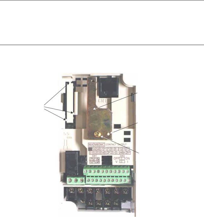
Remove CN2 Protective Cover and Install Mounting Bracket
Remove the plastic protective cover from the CN2 connector on the drive by cutting the three tabs as shown below. Install the option mounting bracket and secure it to the drive with the M3x8 screw provided.
Remove the CN2 protective cover by carefully clipping the three tabs
Cover CN2
Option kit mounting bracket
Align hole in mounting bracket with nib on front of the V7 drive
Secure mounting bracket to V7 drive with M3x8 screw provided
Figure 1.2 – Remove CN2 Cover and Install Option Mounting Bracket
Installation 1-6
Connect Ground Wire
Connect the ground wire to the ground connector on the back of the V7 PROFIBUS-DP Option. Select the wire of the appropriate length based on drive model.
|
|
|
Table 1.2 – Ground Cable & Drive Models |
|
Cable Length |
|
Drive Models |
|
6” (150mm) |
|
20P1, 20P2, 40P2 |
|
8.5” (220mm) |
|
20P4, 20P7, 21P5, 22P2, 23P7, 40P4, 40P7, 43P7, 41P5, 42P2 |
|
12.5” (320mm) |
|
25P5, 27P5, 47P5 |
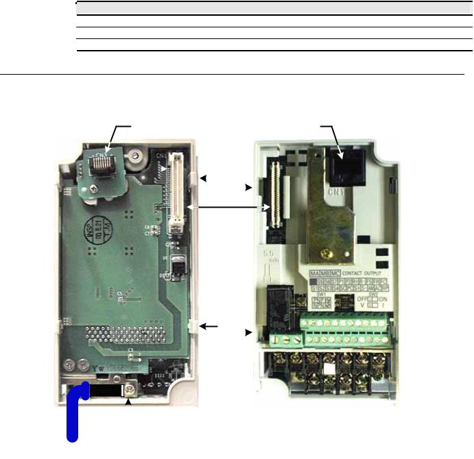
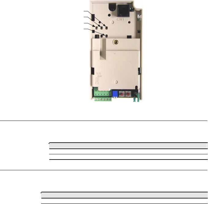
Mount the V7 PROFIBUS-DP Option
Mount the V7 PROFIBUS-DP Option onto the drive by following the instructions below.
CN3 - Male RJ45 |
CN1 - Female |
||
Connector |
RJ45 Connector |
||
Tab |
Slot |
||
|
|
|
|
CN1 - CN2
Tab Slot
E
 Ground Terminal
Ground Wire
Figure 1.3 – Mount the V7 Option
Align the CN1 connector on the back of the option with its mating CN2 connector on the front of the drive.
Simultaneously align the CN3 connector, the male RJ45 connector, on the back of the option with the CN1 connector, the female RJ45 connector, on the front of the drive.
Align the tabs on the option with their corresponding slots on the front of the drive.
Press the option and the drive together until the tabs lock into their associated slots.
Secure the option to the V7 drive by tightening the locking screw at the top-center on the front of the option.
Connect the ground wire from the V7 PROFIBUS-DP Option to the ground terminal on the V7 drive.
Installation 1-7
Connect The V7 To The PROFIBUS-DP Communications Network.
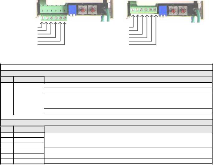
Determine the type of connector on the V7 PROFIBUS-DP Option. Connector Style A is a modified Phoenix pluggable connector. The modification can be seen on the back of the connector as a small circuit board. Connector Style B is a standard Phoenix pluggable connector without modification.
Connect the PROFIBUS-DP network cable to the V7 PROFIBUS-DP Option. Refer to the appropriate connection drawing in Figure 1.4 below for your connector style.
Use standard PROFIBUS-DP cable as specified by the PROFIBUS Organization www.profibus.org. Refer to Appendix C Troubleshooting for more information on network cabling.
Connector Style A |
Connector Style B |
A In (Green) |
|
1 |
Reserved |
|
1 |
|
|
||||
B In (Red) |
|
2 |
Reserved |
|
2 |
|
|
||||
A Out (Green) |
|
3 |
A In/Out (Green) |
|
3 |
B Out (Red) |
|
4 |
B In/Out (Red) |
|
4 |
Shield |
|
5 |
Shield |
|
5 |
Reserved |
|
6 |
Reserved |
|
6 |
|
|
Figure 1.4 – V7 PROFIBUS-DP Option Connections
|
|
Table 1.3 – PROFIBUS-DP Cable Connections |
|
|
Connector Style A |
Pin |
Name |
Function |
1 |
A In-(Green) |
Negative Input RxD/TxD (Connected from the previous device) |
2 |
B-In (Red) |
Positive Input RxD/TxD (Connected from the previous device) |
3 |
A Out-(Green) |
Negative Output RxD/TxD (Connect to the next device) |
4 |
B-Out (Red) |
Positive Output RxD/TxD (Connect to the next device) |
5 |
Shield |
BUS cable shield (Connected to PE internally on the communication option) |
6 |
Reserved |
|
Connector Style B
Pin |
Name |
1 |
Reserved |
2Reserved
3A In/ Out-(Green)
4B-In/Out (Red)
5Shield
6Reserved
Function
Negative Input/Output RxD/TxD
Positive Input/Output RxD/TxD
BUS cable shield (Connected to PE internally on the communication option)
Installation 1-8
Set Node Address
Set the node address for the drive setting the 10‘s digit with S2 and the 1’s digit with S1. All devices on the network must have unique node addresses. Check the network layout to verify that the node address selected is unique, matches the master configuration for that device and falls between 3 – 99.
Address = (Switch 2 x 10) + (Switch 1 x 1)
Example: Set node address to 15
Set address switch 2 to "1 |
Set address switch 1 to "5" |
9 |
0 |
1 |
8 |
|
2 |
|
3 |
|
7 |
|
|
6 |
|
|
5 |
4 |
|
|
||
|
|
|
|
S2 |
|
9 |
0 |
1 |
8 |
|
2 |
|
3 |
|
7 |
|
|
6 |
|
|
5 |
4 |
|
|
||
|
|
S1
Figure 1.5 – Setting the V7 PROFIBUS-DP Option Node Address
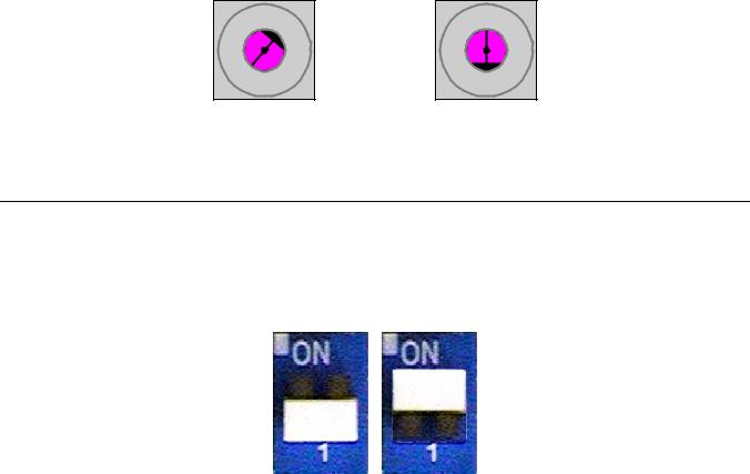
Set Network Termination
If this unit is either the first or the last device on the network, including any PLC and/or PROFIBUS-DP Master, and active termination is not used, set the termination resistor switch to ON. If this device is not the first or last device on the network or active termination is used, set the termination resistor switch to OFF. Active termination is the recommended termination method and is required for networks operating above 1.5Mbps. Active termination will eliminate the possibility of network failure due to the removal of a terminated device. The Siemens Active terminator Module part number is 6ES7 972-0DA00-0AA0.
OFF ON
Figure 1.6 – Termination Switch
Installation 1-9

Verify V7 PROFIBUS-DP Option Operation
Apply power to the drive.
Verify that the diagnostic LEDs on the front of the V7 PROFIBUS-DP Option are in their correct state.
Table 1.4 – Correct Diagnostic LED States
|
|
|
|
|
LED Display |
|
|
|
|
Content |
|
|
Cause |
|
|
||||
|
|
PWR |
|
|
COM |
|
|
ERR |
|
|
WD |
|
|
|
|
|
|
||
|
|
|
|
|
|
|
|
|
|
|
|
|
|
|
|
||||
|
|
Solid Green |
|
Solid Green |
|
OFF |
|
Flashing Green |
|
Normal |
|
Normal communication possible. |
|||||||
Remove power from the drive and wait for the charge lamp to be completely extinguished. Wait at least five additional minutes for the drive to be completely discharged. Measure the DC bus voltage and verify that it is at a safe level.
Secure the communication option to the drive, aligning the recessed screw at the top-center of the option with the threaded hole in the mounting bracket.
Install the operator keypad and terminal cover.
Set drive parameters n003, n004 and n035 to appropriate values.
Table 1.5 – Option Specific Parameter Settings
|
Addr |
|
Param |
Function |
Data |
+/- Limits - Description |
Default |
|
|
|
|
|
|
0 |
Operator keypad |
|
|
|
103h |
|
n003 |
Operation Method Selection |
1 |
Terminal |
1 |
|
|
|
2 |
Serial Communication |
|
||||
|
|
|
|
|
|
|
||
|
|
|
|
|
3 |
Option Card (PROFIBUS-DP Option) |
|
|
|
|
|
|
|
0 |
Operator keypad Pot |
|
|
|
|
|
|
|
1 |
Operator keypad |
|
|
|
|
|
|
|
2 |
Voltage Reference (0-10v) |
|
|
|
|
|
|
|
3 |
Current Reference (4-20 Ma) |
|
|
|
104h |
|
n004 |
Reference Selection |
4 |
Current Reference (0-20 Ma) |
2 |
|
|
|
5 |
Pulse Train Reference |
|
||||
|
|
|
|
|
|
|
||
|
|
|
|
|
6 |
Serial Communication |
|
|
|
|
|
|
|
7 |
Multi-Function Analog Input (0-10vdc) |
|
|
|
|
|
|
|
8 |
Multi-Function Analog Input(4-20ma) |
|
|
|
|
|
|
|
9 |
Option Card (PROFIBUS-DP Option) |
|
|
|
|
|
|
|
0 |
0.01 Hz (< 100hz), 0.1hz (100 Hz >=100hz) |
|
|
|
123h |
|
n035 |
Frequency Reference Unit Selection |
1 |
0.1% |
0 |
|
|
|
2-39 |
Rpm |
|
||||
|
|
|
|
|
|
|
||
|
|
|
|
|
40-3999 |
User Setting |
|
|
Installation 1-10
Option LEDs
The PROFIBUS-DP Option Unit is equipped with four indication LEDs for module and PROFIBUS-DP status indication. The LEDs are located on the unit according to the figure’s below.
Indicator LEDs
ERR
COMM
PWR
WD
Figure 1.8 – V7 PROFIBUS-DP LED Locations
LED Indicators
The following LEDs indicates the PROFIBUS-DP status.
|
|
|
|
Table 1.6 – Communication LEDs |
|
LED |
Color |
|
Indication/Function |
|
COMM |
Green |
|
Lit during data exchange with the PROFIBUS-DP Master . |
|
|
|
|
|
|
ERR |
Red |
|
Lit when no data exchange is taken place. |
Module Status Indicators
The following LEDs indicates the status of the V7 PROFIBUS-DP Option.
|
|
|
|
Table 1.7 – Diagnostic LEDs |
|
|
LED |
Color |
|
|
Indication/Function |
|
PWR |
Green |
Lit when the +5V power to the electronics is OK. Turned off if the +5V is below +4.5V (min) |
||
|
WD |
Red/Green |
Indicates the module status |
|
|
|
|
|
OFF |
|
Communication Option CPU not running. |
|
|
|
Solid Green: |
|
Initialization. |
|
|
|
Flashing green: |
|
Normal operation. |
|
|
|
Solid Red: |
|
Internal Communication Option error. |
|
|
|
|
|
|
|
|
|
Flashing red: |
|
V7 error detected. |
|
|
|
Other indication |
|
Unspecified, Communication Option error |
|
|
|
|
|
|
Installation 1-11

LED Diagnostics
The following table presents the faults displayed by the LEDs on the communication option, their causes, and solutions.
Table 1.8 – LED Diagnostics
|
|
|
|
LED Display |
|
|
|
|
Content |
|
|
Cause |
|
|
Solutions |
|
||||
|
PWR |
|
|
COM |
|
|
ERR |
|
|
WD |
|
|
|
|
|
|
|
|
|
|
|
|
|
|
|
|
|
|
|
|
|
|
|
|
|
|
Power is not being supplied |
• |
Check the main circuit wiring on the drive. |
||
|
|
|
|
|
|
|
|
|
|
|
|
|
Power |
|
from the drive. |
• |
Cycle drive power. |
|||
|
OFF |
|
OFF |
|
OFF |
|
OFF |
|
|
Power is not being supplied to |
• Turn of the drive power. |
|||||||||
|
|
|
|
|
|
|
|
|
|
|
|
|
OFF |
|
• |
Check the option unit connection to the |
||||
|
|
|
|
|
|
|
|
|
|
|
|
|
|
|
|
the option unit due to poor |
|
drive. |
||
|
|
|
|
|
|
|
|
|
|
|
|
|
|
|
|
option unit connection. |
• |
|||
|
|
|
|
|
|
|
|
|
|
|
|
|
|
|
|
Cycle drive power. |
||||
|
|
|
|
|
|
|
|
|
|
|
|
|
|
|
|
|
|
|||
|
Solid |
|
OFF |
|
Solid |
|
Solid |
|
CPU |
|
Option unit CPU error. |
• |
Cycle drive power. |
|||||||
|
Green |
|
|
Red |
|
Red |
|
Error |
|
• Replace option unit if fault persists. |
||||||||||
|
|
|
|
|
|
|
|
|
|
|||||||||||
|
|
|
|
|
|
|
|
|
|
|
|
|
|
|
|
|
|
• |
Cycle drive power. |
|
|
Solid |
|
OFF |
|
Solid |
|
Flashing |
|
Drive |
|
Error in Drive unit. |
• Replace V7 PROFIBUS-DP Option if fault |
||||||||
|
Green |
|
|
Red |
|
Red |
|
Error |
|
|
persists |
|||||||||
|
|
|
|
|
|
|
|
|
|
|
||||||||||
|
|
|
|
|
|
|
|
|
|
|
|
|
|
|
|
|
|
• Replace drive if fault persists. |
||
|
|
|
|
|
|
|
|
|
|
|
|
|
|
|
|
|
|
• Check whether the address set in the |
||
|
|
|
|
|
|
|
|
|
|
|
|
|
|
|
|
|
|
|
PROFIBUS-DP Master differs from the |
|
|
|
|
|
|
|
|
|
|
|
|
|
|
|
|
|
|
|
|
address of the option unit. |
|
|
|
|
|
|
|
|
|
|
|
|
|
|
|
|
|
|
|
• Check that the master is functioning |
||
|
|
|
|
|
|
|
|
|
|
|
|
|
|
|
|
|
|
|
properly. |
|
|
Solid |
|
OFF |
|
Flashing |
|
Solid |
|
Com |
|
A fault has occurred rendering |
• Check that the termination resistor is |
||||||||
|
|
|
|
|
|
|
correctly connected to the communication |
|||||||||||||
|
Green |
|
|
Red |
|
Green |
|
Error |
|
communication impossible. |
|
|||||||||
|
|
|
|
|
|
|
|
|
line. |
|||||||||||
|
|
|
|
|
|
|
|
|
|
|
|
|
|
|
|
|
|
|
||
|
|
|
|
|
|
|
|
|
|
|
|
|
|
|
|
|
|
• Check whether the communication line is |
||
|
|
|
|
|
|
|
|
|
|
|
|
|
|
|
|
|
|
|
correctly connected (disconnected or poor |
|
|
|
|
|
|
|
|
|
|
|
|
|
|
|
|
|
|
|
|
connection). |
|
|
|
|
|
|
|
|
|
|
|
|
|
|
|
|
|
|
|
• Check that the communication line is |
||
|
|
|
|
|
|
|
|
|
|
|
|
|
|
|
|
|
|
|
separated from the main power line. |
|
|
Solid |
|
Solid |
|
Flashing |
|
Solid |
|
Com |
|
A fault has occurred rendering |
• Check whether the address is duplicated |
||||||||
|
|
|
|
|
|
|
with any other devices within the |
|||||||||||||
|
Green |
|
Green |
|
Red |
|
Green |
|
Error |
|
communication impossible. |
|
||||||||
|
|
|
|
|
|
|
PROFIBUS-DP network. |
|||||||||||||
|
|
|
|
|
|
|
|
|
|
|
|
|
|
|
|
|
|
|
||
|
Solid |
|
Solid |
|
OFF |
|
Solid |
|
CPU |
|
Option unit under initialization |
• |
Wait until WD LED is flashing |
|||||||
|
Green |
|
Green |
|
|
Green |
|
Init |
|
|||||||||||
|
|
|
|
|
|
|
|
|
|
|
|
|
||||||||
|
Solid |
|
Solid |
|
OFF |
|
Flashing |
|
Normal |
|
Normal communication |
|
|
|
||||||
|
Green |
|
Green |
|
|
Green |
|
|
possible. |
|
|
|
||||||||
|
|
|
|
|
|
|
|
|
|
|
|
|
||||||||
Installation 1-12

Drive Faults
The following is a table of faults caused by the communication option that will be displayed on the V7 Operator Keypad, their causes, and possible solutions. For any fault displayed on the operator that is not listed in the following table, please see the V7 Technical Manual.
|
|
Table 1.9 – Drive Faults |
|
Fault |
Content |
Cause |
Solution |
|
|
Communication is not established |
• |
|
|
BUS |
Option Com Error |
between PROFIBUS-DP Master and |
Check PROFIBUS-DP communication LED display. |
||
|
|
the drive. |
|
|
|
EF0 |
External Fault from Option |
External fault is active from |
• Turn OFF external fault input. |
||
PROFIBUS-DP option. |
|||||
|
|
|
|
||
F06 |
Option Connection Fault |
The drive and communication are not |
• Turn OFF the drive power supply and check the connection |
||
|
of the option unit and drive, and then, turn ON the drive |
||||
correctly connected. |
|
||||
|
|
|
power supply. If the fault persists, change the option unit. |
||
|
|
|
|
||
F21 |
Communication Option Self- |
|
|
|
|
diagnostic Fault |
|
|
|
||
|
|
|
|
||
F22 |
Com Option Model Code No. |
Communication option is not working. |
• |
Turn the drive power supply back ON. If the fault persists, |
|
Fault |
|
replace the option unit. |
|||
|
|
|
|||
F23 |
Com Option Mutual Diagnostic |
|
|
|
|
Fault |
|
|
|
||
|
|
|
|
||
Installation 1-13

Parameter Settings
The following sections describe the parameters in the V7 that affect communications through the PROFIBUS-DP Communication Option. For complete information on V7 drive parameters refer to the V7 MODBUS→ Technical Manual.
Run/Stop and Frequency Selection
The run/stop and frequency reference commands can originate from serial communication, the operator keypad, external terminals, or the PROFIBUS-DP Option. Parameter n003 (Operation Method Selection) allows the selection of the origin of the run/stop commands. Parameter n004 (Reference Selection) allows the selection of the origin of the frequency reference. The run/stop and frequency reference commands may have different origins. The run/stop command may be set to External Terminals (n003 = 1) while the Frequency Reference may be set to Option Card (PROFIBUS-DP Option) (n004 = 9).
|
|
|
Table 1.10 – Operation Method Selection |
|
n003 |
|
Operation Method Selection (Run/Stop) |
|
|
|
|
0Operator keypad
1External Terminals (Default setting is 1)
2Serial Communication
3Option Card (PROFIBUS-DP Option)
|
|
|
Table 1.11 – Frequency Reference Source Selection |
|
n004 |
|
Frequency Reference Selection |
|
|
|
|
0Operator keypad Pot
1Operator keypad
2Voltage Reference (0-10V) (Default setting is 2)
3Current Reference (4 to 20 mA)
4Current Reference (0 to 20 mA)
5Pulse Train Reference
6Serial Communications (Parameter Access)
7MultiFunction Analog Input (0 to 10V)
8Multi-Function Analog Input (4 to 20mA)
9Option Card (PROFIBUS-DP Option)
Installation 1-14
Operator Display Mode
Parameter n035 sets the scaling and units of the frequency reference and output frequency on the operator keypad.. It also determines the scaling and units of the Speed Command, Speed Reference, and Output Frequency used by the PROFIBUS-DP Option
|
|
Table 1.12 – Operator keypad Display Mode |
|
|
n035 |
Description |
|
|
|
|
|
00.1hz
10.1%
2 – 39 |
RPM (number of motor poles) |
40 - 3999 |
User setting |
Frequency Reference Units
Parameter n152 sets the resolution of the frequency reference and output frequency monitor. The output frequency resolution of the operator keypad is settable via n035, Frequency Reference Unit Selection. If the operator keypad resolution is set to 0.1 Hz (n035=0), and the resolution is changed to 0.01 Hz in n152, the value in the hundredths digit rounded off when displayed on the operator keypad.
|
|
|
Table 1.13 – Frequency Reference Unit Selection |
|
n152 |
|
Frequency Reference Unit Selection |
|
|
|
|
00.1 Hz (Default setting is 0)
10.01 Hz
2100% / 30,000
30.1%
Installation 1-15
Loading...