


XJ600S
Table of contents
 Loading...
4BR-28199-E7
OWNER’S MANUAL
XJ600S

EAU03338
INTRODUCTION
Welcome to the Yamaha world of motorcycling!
As the owner of an XJ600S/XJ600N, you are benefiting from Yamaha’s vast experi-
ence and newest technology regarding the design and manufacture of high-quality
products, which have earned Yamaha a reputation for dependability.
Please take the time to read this manual thoroughly, so as to enjoy all advantages of
your XJ600S/XJ600N. The owner’s manual does not only instruct you in how to
operate, inspect and maintain your motorcycle, but also in how to safeguard yourself
and others from trouble and injury.
In addition, the many tips given in this manual will help keep your motorcycle in the
best possible condition. If you have any further questions, do not hesitate to contact
your Yamaha dealer.
The Yamaha team wishes you many safe and pleasant rides. So, remember to put
safety first!

EAU00005
IMPORTANT MANUAL INFORMATION
Particularly important information is distinguished in this manual by the following notations:
The Safety Alert Symbol means ATTENTION! BECOME ALERT! YOUR SAFETY IS
INVOLVED!
WARNING
Failure to follow WARNING instructions could result in severe injury or death to the
motorcycle operator, a bystander, or a person insp ecting or repairing the motorcycle.
CAUTION:
A CAUTION indicates special precautions that must be taken to avoid damage to the
motorcycle.
NOTE:
A NOTE provides key information to make procedures easier or clearer.
NOTE:
@
●
This manual should be considered a permanent part of this motorcycle and should remain
with it even if the motorcycle is subsequently sold.
●
Yamaha continually seeks advancements in product design and quality. Therefore, while
this manual contains the most current product information available at the time of printing,
there may be minor discrepancies between your motorcycle and this manual. If you have
any questions concerning this manual, please consult your Yamaha dealer.
@

IMPORTANT MANUAL INFORMATION
EW000002
WARNING
@
PLEASE READ THIS MANUAL CAREFULLY AND COMPLETELY BEFORE OPERATING
THIS MOTORCYCLE.
@
IMPORTANT MANUAL INFORMATION
EAU03337
XJ600S/XJ600N
OWNER’S MANUAL
© 2000 by Yamaha Motor Co., Ltd.
1st Edition, May 2000
All rights reserved.
Any reprinting or unauthorized use
without the written permission of
Yamaha Motor Co., Ltd.
is expressly prohibited.
Printed in Japan.
TABLE OF CONTENTS
1 GIVE SAFETY THE RIGHT OF WAY
1
2 DESCRIPTION
2
3 INSTRUMENT AND CONTROL FUNCTIONS
3
4 PRE-OPERATION CHECKS
4
5 OPERATION AND IMPORTANT RIDING POINTS
5
6 PERIODIC MAINTENANCE AND MINOR REPAIR
6
7 MOTORCYCLE CARE AND STORAGE
7
8 SPECIFICATIONS
8
9 CONSUMER INFORMATION
9
INDEX
EAU00009

GIVE SAFETY THE RIGHT OF WAY
1
GIVE SAFETY THE RIGHT OF WAY ......................... ... ... ... ... .... ... ... . 1-1

1
1-1
1-
GIVE SAFETY THE RIGHT OF WAY
EAU00021
Motorcycles are fascinating vehicles, which can give you an unsurpassed feeling of power and
freedom. However, they also impose certain limits, which you must accept; even the best motorcycle
does not ignore the laws of physics.
Regular care and maintenance are essential for preserving value and operating condition of your
motorcycle. Moreover, what is true for the motorcycle is also true for the rider: good performance
depends on being in good shape. Riding under the influence of medication, drugs and alcohol is, of
course, out of the question. Motor cycle riders—more t han car drivers—must always be at their ment al
and physical best. Under the influence of even small amounts of alcohol, there is a tendency to take
dangerous risks.
Protective clothing is as essential for the motorcycle rider as seat belts are for car drivers and
passengers. Always wear a complete motorcycle suit (whether made of leather or tear-resistant
synthetic materials with protectors), sturdy boots, motorcycle gloves and a properly fitting helmet.
Optimum protective wear, however, should not encourage carelessness. Although full-coverage
helmets and suits, in particular, create an illusion of total safety and protection, motorcyclists will
always be vulnerable. Riders who lack critical self-control run the risk of going too fast and are apt to
take chances. This is even more dangerous in wet weather. The good motorcyclist rides safely,
predictably and defensively—avoiding all dangers, including those caused by others.
Enjoy your ride!
DESCRIPTION
2
Left view (XJ600S).............................................................................2-1
Right view (XJ600S)...........................................................................2-2
Controls and instruments (XJ600S)................................................... 2-3
Left view (XJ600N)............................................................................. 2-4
Right view (XJ600N) .......................................................................... 2-5
Controls and instruments (XJ600N)................................................... 2-6
2-1
2
EAU00026
2-
DESCRIPTION
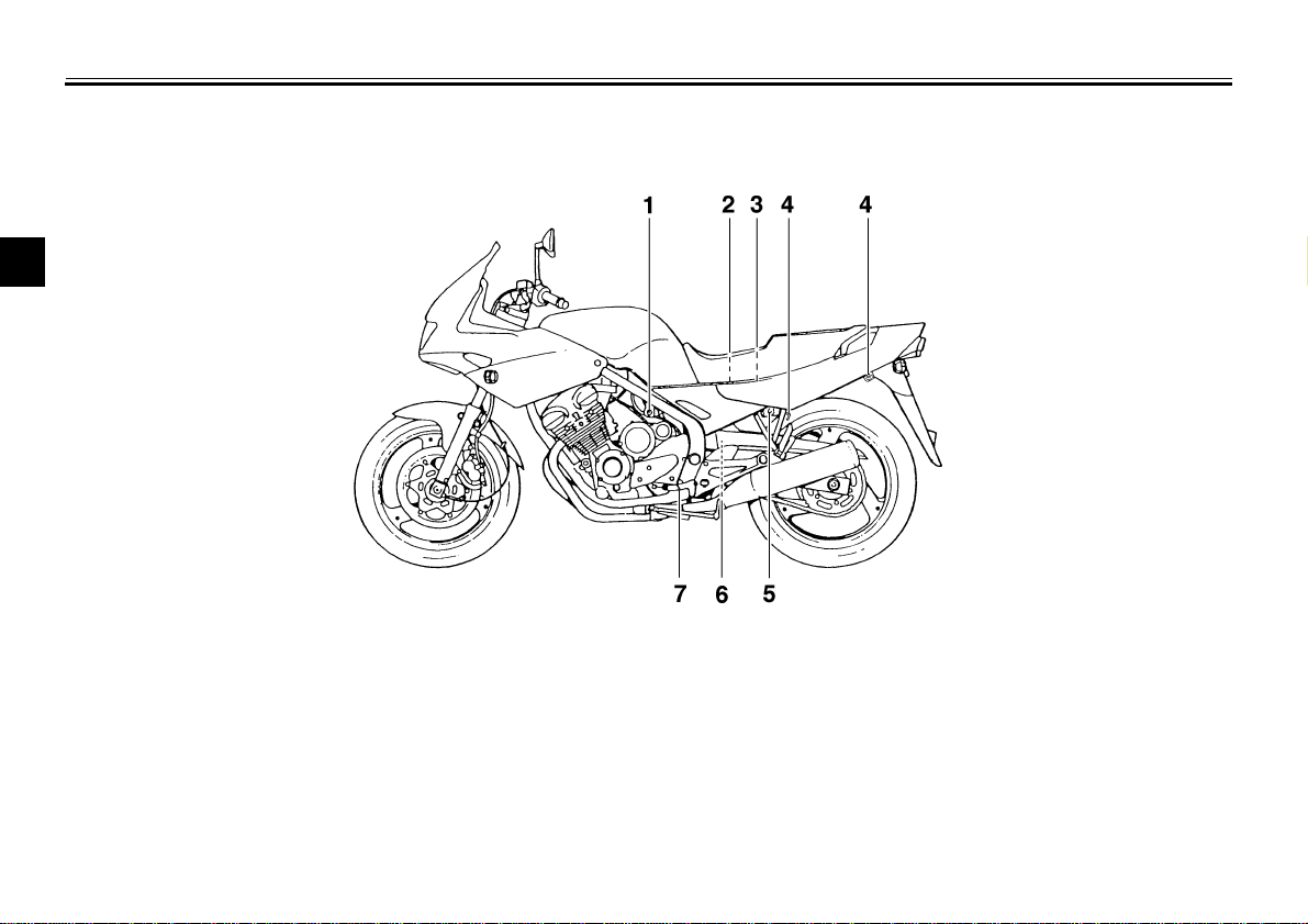
Left view (XJ600S)
1.Fuel cock (page 3-11)
2.Helmet holder (page 3-13)
3.Fuse box (page 6-29)
4.Luggage strap holders (page 3-15)
5.Seat lock (page 3-12)
6.Rear shock absorber spring
preload adjusting ring (page 3-14)
7.Shift pedal (page 3-8)
DESCRIPTION
2-2
2
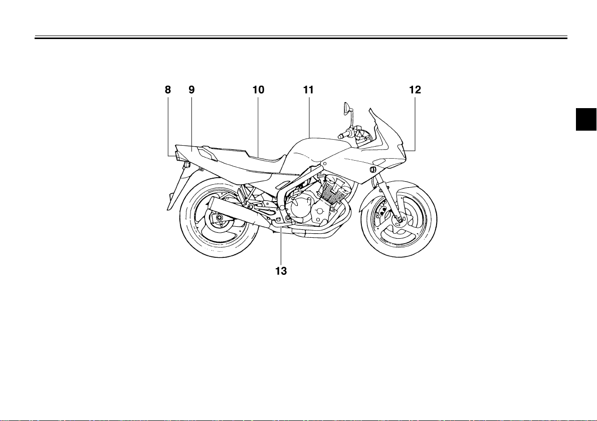
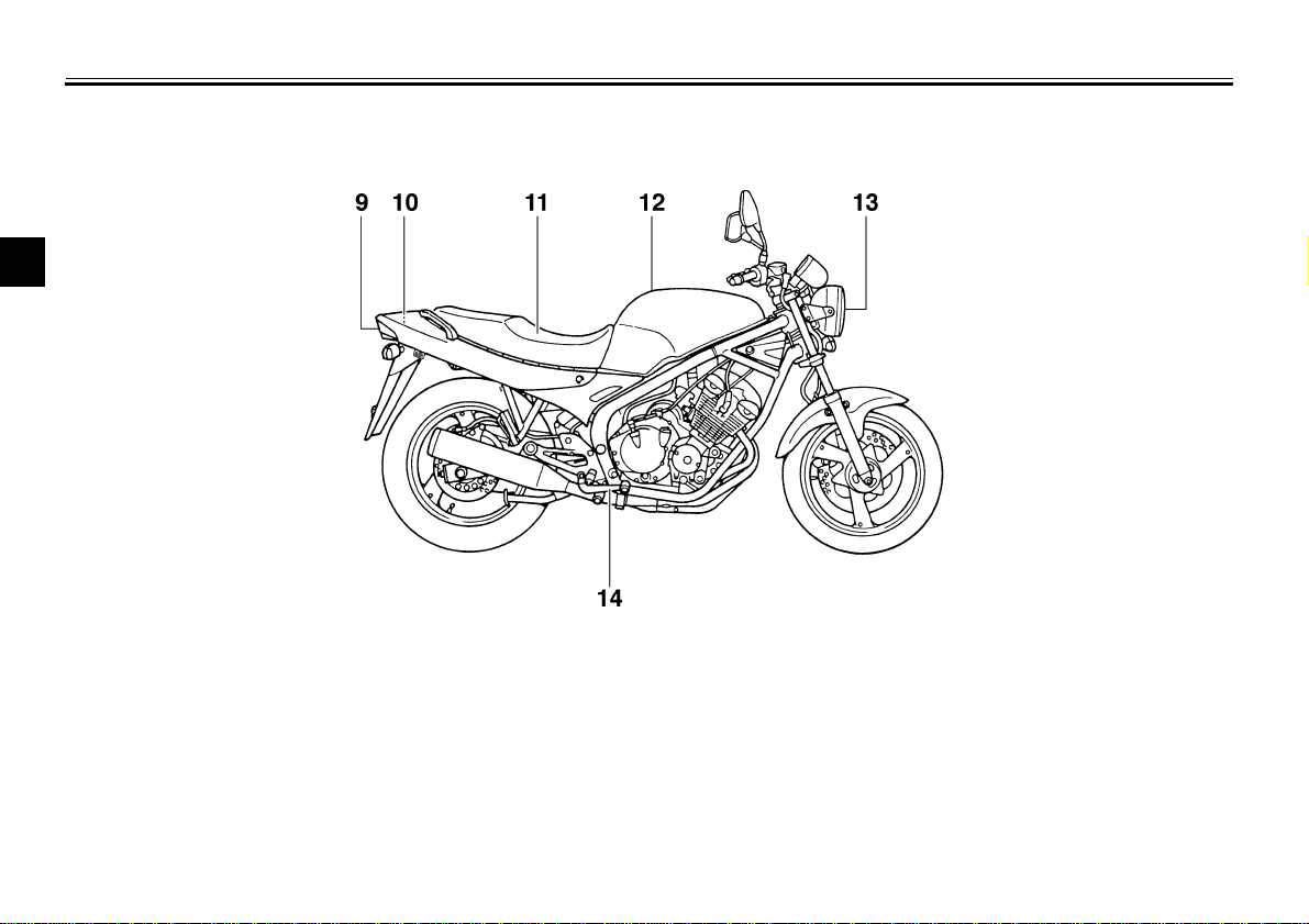
Right view (XJ600S)
8.Tail/brake light
9.Storage compartment (page 3-13)
10.Seat (page 3-12)
11.Fuel tank (page 3-9)
12.Headlight (page 6-30)
13.Brake pedal (page 3-9)

DESCRIPTION
2-3
2
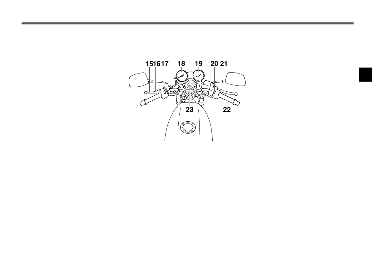
Controls and instruments (XJ600S)
14.Clutch lever (page 3-7)
15.Left handlebar switches (page 3-6)
16.Starter (choke) lever (page 3-12)
17.Speedometer unit (page 3-4)
18.Tachometer (page 3-5)
19.Right handlebar switches (page 3-7)
20.Brake lever (page 3-8)
21.Throttle grip (page 6-13)
22.Main switch/steering lock (page 3-1)

DESCRIPTION
2-4
2
Left view (XJ600N)
1.Steering lock (page 3-3)
2.Fuel cock (page 3-11)
3.Helmet holder (page 3-13)
4.Fuse box (page 6-29)
5.Luggage strap holders (page 3-15)
6.Seat lock (page 3-12)
7.Rear shock absorber spring preload
adjusting ring (page 3-14)
8.Shift pedal (page 3-8)
DESCRIPTION
2-5
2
Right view (XJ600N)
9.Tail/brake light
10.Storage compartment (page 3-13)
11.Seat (page 3-12)
12.Fuel tank (page 3-9)
13.Headlight (page 6-30)
14.Brake pedal (page 3-9)
DESCRIPTION
2-6
2
Controls and instruments (XJ600N)
15.Clutch lever (page 3-7)
16.Left handlebar switches (page 3-6)
17.Starter (choke) lever (page 3-12)
18.Speedometer unit (page 3-5)
19.Tachometer (page 3-5)
20.Right handlebar switches (page 3-7)
21.Brake lever (page 3-8)
22.Throttle grip (page 6-13)
23.Main switch (page 3-1)

3
INSTRUMENT AND CONTROL FUNCTIONS
Main switch/steering lock .....................................3-1
Steering lock (for XJ600N)....................................3-3
Indicator lights .....................................................3-3
Speedometer unit (for XJ600S) ...........................3-4
Speedometer unit (for XJ600N) ...........................3-5
Tachometer .......................................................... 3-5
Handlebar switches .......................................... ...3-6
Clutch lever ..........................................................3-7
Shift pedal ............................................................3-8
Brake lever ..........................................................3-8
Brake pedal ..........................................................3-9
Fuel tank cap .......................................................3-9
Fuel ................................................................... 3-10
Fuel tank breather hose (for Germany only) ..... 3-10
Fuel cock ........................................................... 3-11
Starter (choke) lever .......................................... 3-12
Seat ................................ ...................... ............. 3- 12
Helmet holders .................................................. 3-13
Storage compartment .......... ... .......................... 3-1 3
Adjusting the shock absorber assembly ............ 3-14
Luggage strap holders ................................... ... 3-15
Sidestand .......................................................... 3-15
Ignition circuit cut-off system ............................. 3-16
3-1
3
EAU00027
3-
INSTRUMENT AND CONTROL FUNCTIONS
EAU00029
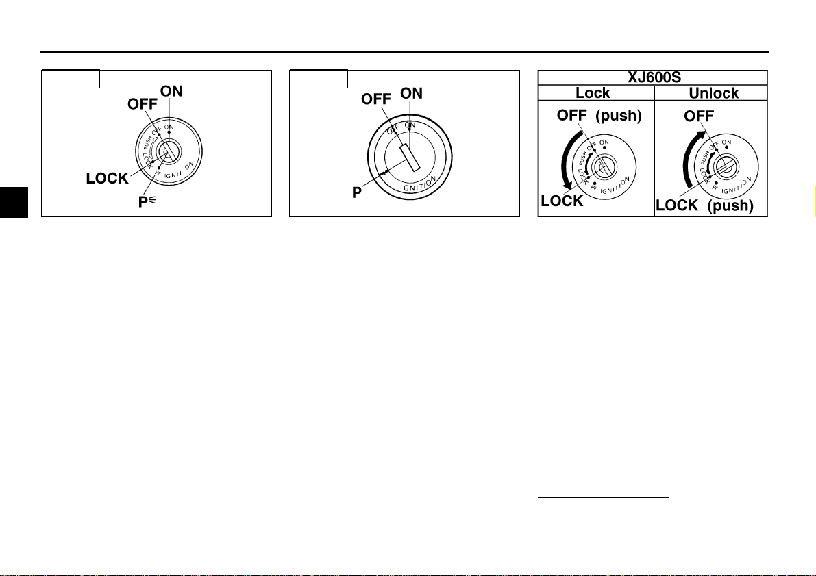
Main switch/steering lock
The main switch/steering lock controls
the ignition and lighting systems, and is
used to lock the steering. The various
positions are described below.
EAU00036
ON
All electrical systems are supplied with
power, and the engine can be started.
The key cannot be removed.
EAU00038
OFF
All electrical systems are off. The key
can be removed.
EAU00040
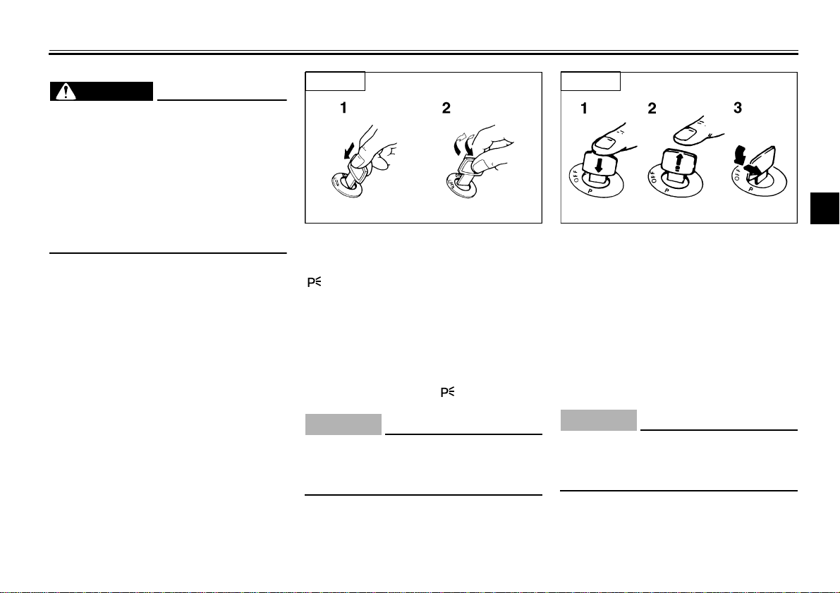
LOCK (for XJ600S)
The steering is locked, and all electrical
systems are off. The key can be re-
moved.
To lock the steering
1. Turn the handlebars all the way to
the left.
2. Push the key in from the “OFF” po-
sition, and then turn it to “LOCK”
while still pushing it.
3. Remove the key.
To unlock the steering
Push the key in, and then turn it to
“OFF” while still pushing it.
XJ600S XJ600N
INSTRUMENT AND CONTROL FUNCTIONS
3-2
3
EW000016
WARNING
@
Never turn the key to “OFF” or
“LOCK” while the motorcycle is
moving, otherwise the electrical
systems will be switched off, which
may result in loss of control or an
accident. Make sure that the motor-
cycle is stopped before turning the
key to “OFF” or “LOCK”.
@
EAU01590
(Parking) (for XJ600S)
The steering is locked, and the taillight
and auxiliary light are on, but all other
electrical systems are off. The key can
be removed.
The steering must be locked before the
key can be turned to “ ”.
ECA00043
CAUTION:
@
Do not use the parking position for
an extended length of time, other-
wise the battery may discharge.
@
EAU00055
P (Parking) (for XJ600N)
The taillight and auxiliary light are on,
but all other electrical systems are off.
The key can be removed.
The key must be pushed in, and then
released before it can be turned to “P”.
ECA00043
CAUTION:
@
Do not use the parking position for
an extended length of time, other-
wise the battery may discharge.
@
1. Push.
2. Turn.
XJ600S
1. Push.
2. Release.
3. Turn.
XJ600N
INSTRUMENT AND CONTROL FUNCTIONS
3-3
3
EAU02934
Steering lock (for XJ600N)
To lock the steering
1. Turn the handlebar all the way to
right.
2. Open the steering lock cover, and
then insert the key.
3. Turn the key 1/8 turn counter-
clockwise, push it in while turning
the handlebar slightly to the left,
and then turn the key 1/8 turn
clockwise.
4. Check that the steering is locked,
remove the key, and then close
the lock cover.
To unlock the steering
1. Open the steering lock cover, and
then insert the key.
2. Push the key in, turn it 1/8 turn
counterclockwise so that it moves
out, and then release it.
3. Remove the key, and then close
the lock cover.
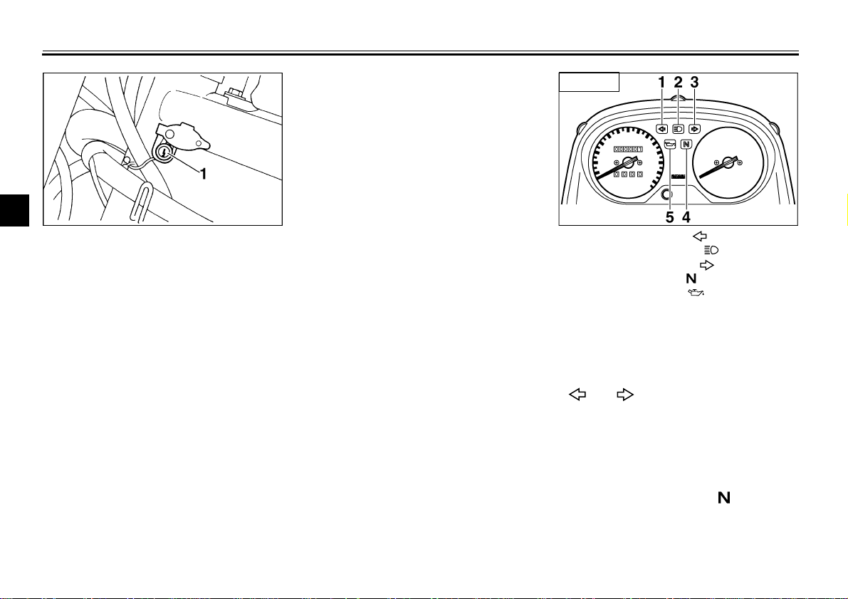
EAU03034
Indicator and warning lights
EAU03299
Turn signal indicator lights
“ ” / “ ”
The corresponding indicator light flash-
es when the turn signal switch is
pushed to the left or right.
EAU00061
Neutral indicator light “ ”
This indicator light comes on when the
transmission is in the neutral position.
1. Steering lock 1. Left turn indicator light “ ”
2. High beam indicator light “ ”
3. Right turn indicator light “ ”
4. Neutral indicator light “ ”
5. Oil level warning light “ ”
XJ600S
INSTRUMENT AND CONTROL FUNCTIONS
3-4
3
EAU00063
High beam indicator light “ ”
This indicator light comes on when the
high beam of the headlight is switched
on.
EAU03201
Oil level warning light “ ”
This warning light comes on when the
engine oil level is low.
The electrical circuit of the warning light
can be checked according to the fol-
lowing procedure.
1. Set the engine stop switch to “ ”
and turn the key to “ON”.
2. Shift the transmission into the neu-
tral position or pull the clutch lever.
3. Push the start switch. If the warn-
ing light does not come on while
pushing the start switch, have a
Yamaha dealer check the electri-
cal circuit.
NOTE:
@
Even if the oil level is sufficient, the
warning light may flicker when riding on
a slope or during sudden acceleration
or deceleration, but this is not a mal-
function.
@
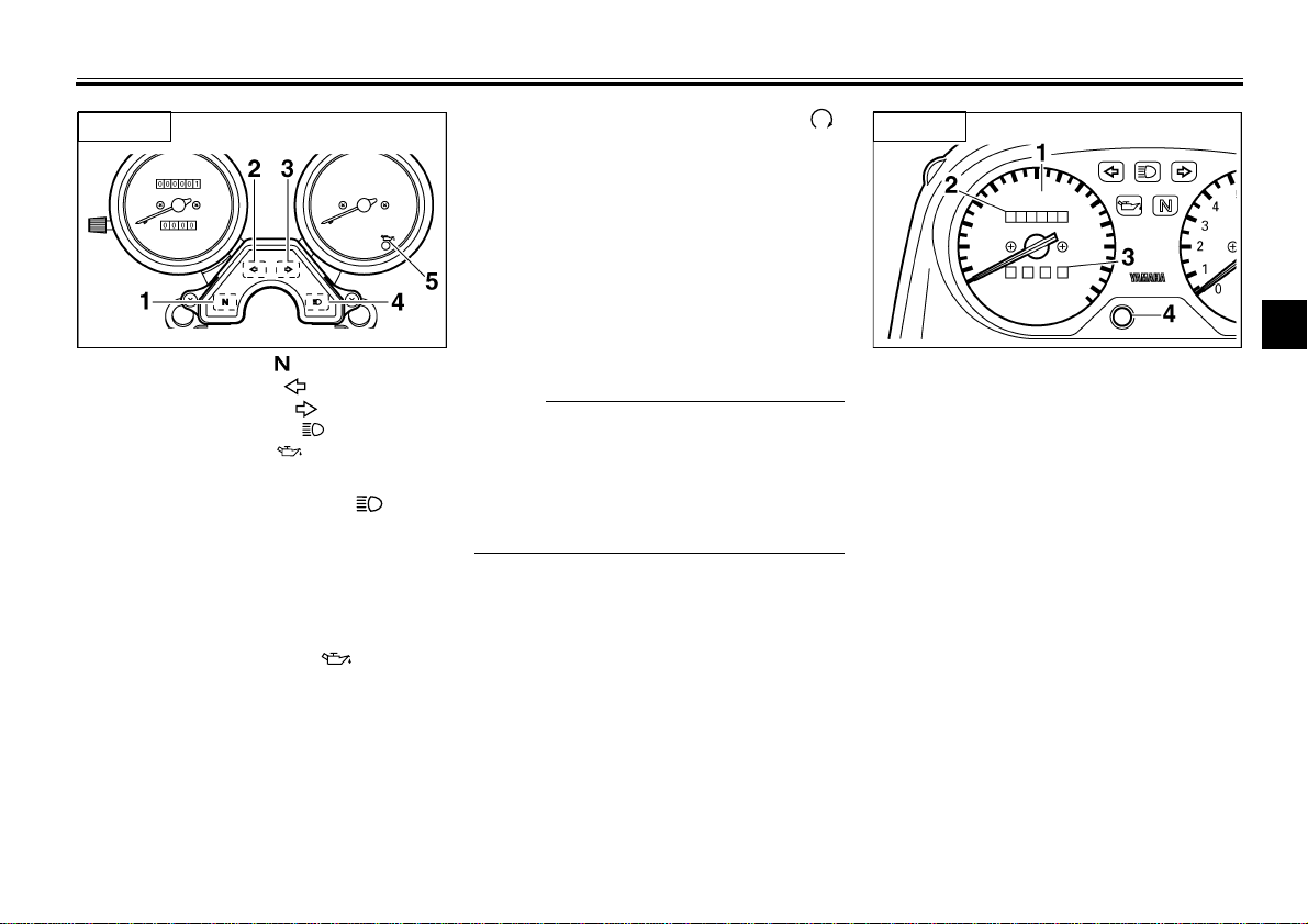
EAU00094
Speedometer unit (for XJ600S)
The speedometer unit is equipped with
a speedometer, an odometer and a
tripmeter. The speedometer shows
riding speed. The odometer shows the
total distance traveled. The tripmeter
shows the distance traveled since it
was last set to zero with the reset but-
ton. The tripmeter can be used to esti-
mate the distance that can be traveled
with a full tank of fuel. This information
will enable you to plan future fuel stops.
1. Neutral indicator light “ ”
2. Left turn indicator light “ ”
3. Right turn indicator light “ ”
4. High beam indicator light “ ”
5. Oil level warning light “ ”
XJ600N
1. Speedometer
2. Odometer
3. Tripmeter
4. Reset button
XJ600S
INSTRUMENT AND CONTROL FUNCTIONS
3-5
3
EAU00095
Speedometer unit (for XJ600N)
The speedometer unit is equipped with
a speedometer, an odometer and a
tripmeter. The speedometer shows
riding speed. The odometer shows the
total distance traveled. The tripmeter
shows the distance traveled since it
was last set to zero with the reset knob.
The tripmeter can be used to estimate
the distance that can be traveled with a
full tank of fuel. This information will en-
able you to plan future fuel stops.
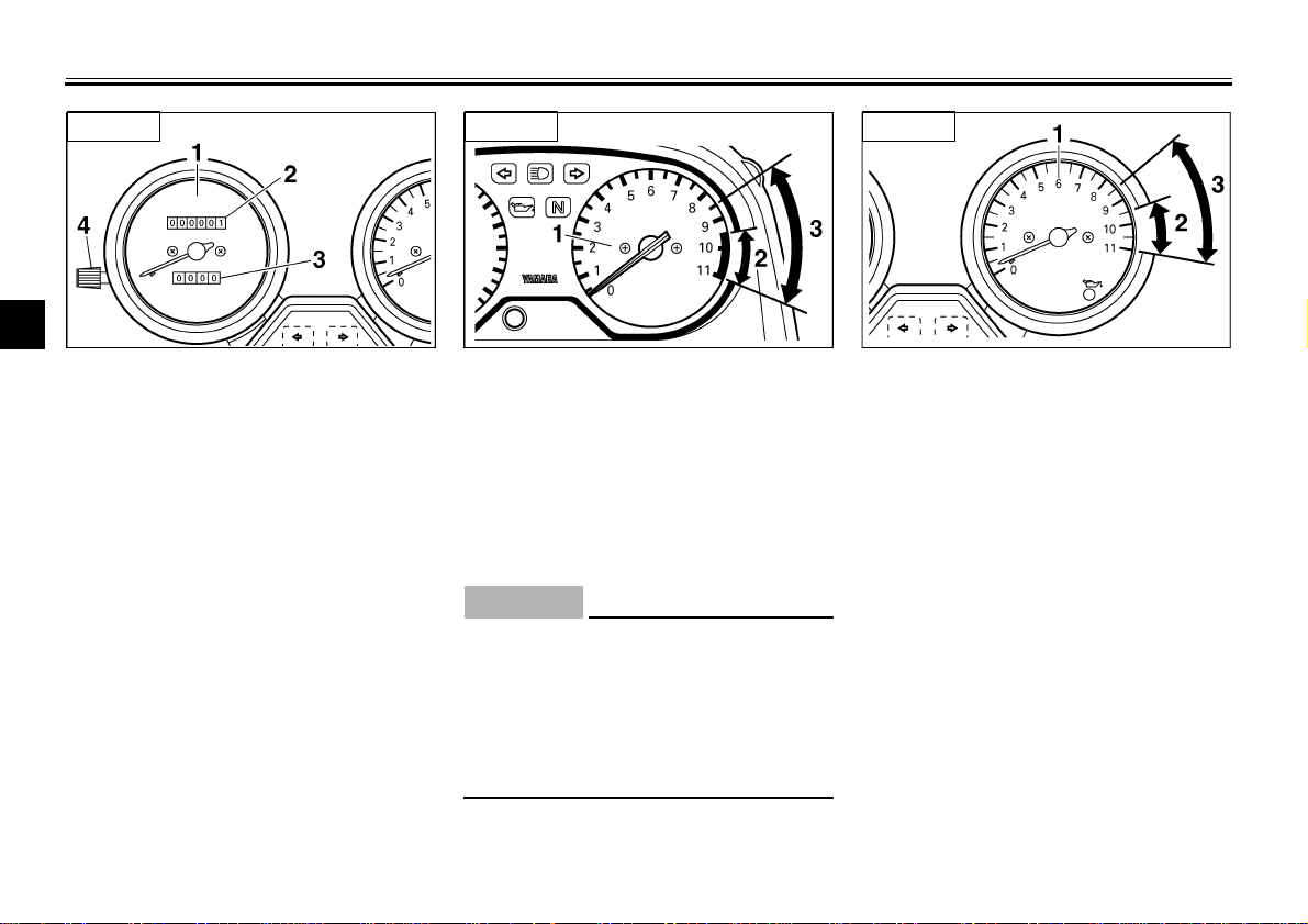
EAU00101
Tachometer
The electric tachometer allows the rider
to monitor the engine speed and keep it
within the ideal power range.
EC000003*
CAUTION:
@
Do not operate the engine in the ta-
chometer red zone.
Red zone: 9,500 r/min and above
(except for CH, A)
8,500 r/min and above
(for CH, A)
@
1. Speedometer
2. Odometer
3. Tripmeter
4. Reset knob
XJ600N
1. Tachometer
2. Red zone (except for CH, A)
3. Red zone (for CH, A)
XJ600S
1. Tachometer
2. Red zone (except for CH, A)
3. Red zone (for CH, A)
XJ600N
INSTRUMENT AND CONTROL FUNCTIONS
3-6
3
EAU00118
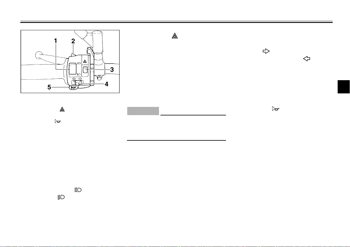
Handlebar switches
EAU00120
Pass switch “PASS”
Press this switch to flash the headlight.
EAU00121
Dimmer switch
Set this switch to “ ” for the high
beam and to “ ” for the low beam.
EAU00144
Hazard switch “ ”
With the key in the “ON” or “P” position,
use this switch to turn on the hazard
light (simultaneous flashing of all turn
signal lights).
The hazard light is used in case of an
emergency or to warn other drivers
when your motorcycle is stopped
where it might be a traffic hazard.
EC000006
CAUTION:
@
Do not use the hazard light for an ex-
tended length of time, otherwise the
battery may discharge.
@
EAU00127
Turn signal switch
To signal a right-hand turn, push this
switch to “ ”. To signal a left-hand
turn, push this switch to “ ”. When
released, the switch returns to the cen-
ter position. To cancel the turn signal
lights, push the switch in after it has re-
turned to the center position.
EAU00129
Horn switch “ ”
Press this switch to sound the horn.
1. Dimmer switch
2. Pass switch “PASS”
3. Hazard switch “ ”
4. Turn signal switch
5. Horn switch “ ”
INSTRUMENT AND CONTROL FUNCTIONS
3-7
3
EAU00138
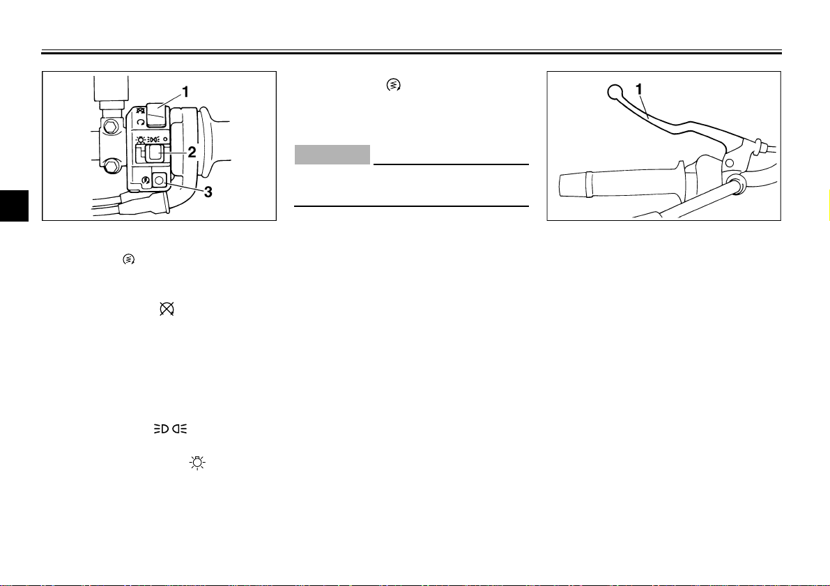
Engine stop switch
Set this switch to “ ” to stop the en-
gine in case of an emergency, such as
when the motorcycle overturns or
when the throttle cable is stuck.
EAU00134
Light switch
Set this switch to “ ” to turn on the
auxiliary light, meter lighting and tail-
light. Set the switch to “ ” to turn on
the headlight also.
EAU00143
Start switch “ ”
Push this switch to crank the engine
with the starter.
EC000005
CAUTION:
@
See page 5-1 for starting instruc-
tions prior to starting the engine.
@
EAU00152
Clutch lever
The clutch lever is located at the left
handlebar grip. To disengage the
clutch, pull the lever toward the handle-
bar grip. To engage the clutch, release
the lever. The lever should be pulled
rapidly and released slowly for smooth
clutch operation.
The clutch lever is equipped with a
clutch switch, which is part of the igni-
tion circuit cut-off system. (See page
3-16 for an explanation of the ignition
circuit cut-off system.)
1. Engine stop switch
2. Light switch
3. Start switch “ ”
1. Clutch lever
INSTRUMENT AND CONTROL FUNCTIONS
3-8
3
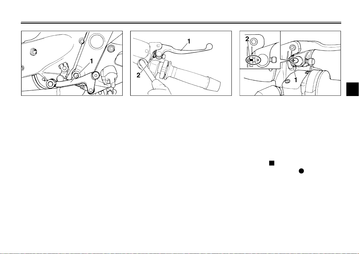
EAU00157
Shift pedal
The shift pedal is located on the left
side of the engine and is used in com-
bination with the clutch lever when
shifting the gears of the 6-speed con-
stant-mesh transmission equipped on
this motorcycle.
EAU00160
Brake lever
The brake lever is located at the right
handlebar grip. To apply the front
brake, pull the lever toward the handle-
bar grip.
The brake lever is equipped with a po-
sition adjusting nut. To adjust the dis-
tance between the brake lever and the
handlebar grip, turn the adjusting nut
while holding the lever pushed away
from the handlebar grip. Make sure that
the mark “ ” on the adjusting nut is
aligned with the mark “ ” on the brake
lever.
1. Shift pedal 1. Brake lever
2. Position adjusting nut
1. Brake lever position adjusting nut
2. Properly aligned marks

INSTRUMENT AND CONTROL FUNCTIONS
3-9
3
EAU00162
Brake pedal
The brake pedal is on the right side of
the motorcycle. To apply the rear
brake, press down on the brake pedal.
EAU02935
Fuel tank cap
To open the fuel tank cap
Open the fuel tank cap lock cover, in-
sert the key into the lock, and then turn
it 1/4 turn clockwise. The lock will be re-
leased and the fuel tank cap can be
opened.
To close the fuel tank cap
1. Push the fuel tank cap into position
with the key inserted in the lock.
2. Turn the key counterclockwise to
the original position, remove it,
and then close the lock cover.
NOTE:
@
The fuel tank cap cannot be closed un-
less the key is in the lock. In addition,
the key cannot be removed if the cap is
not properly closed and locked.
@
EWA00025
WARNING
@
Make sure that the fuel tank cap is
properly closed before riding.
@
1. Brake pedal 1. Fuel tank cap lock cover
2. Unlock.
INSTRUMENT AND CONTROL FUNCTIONS
3-10
3
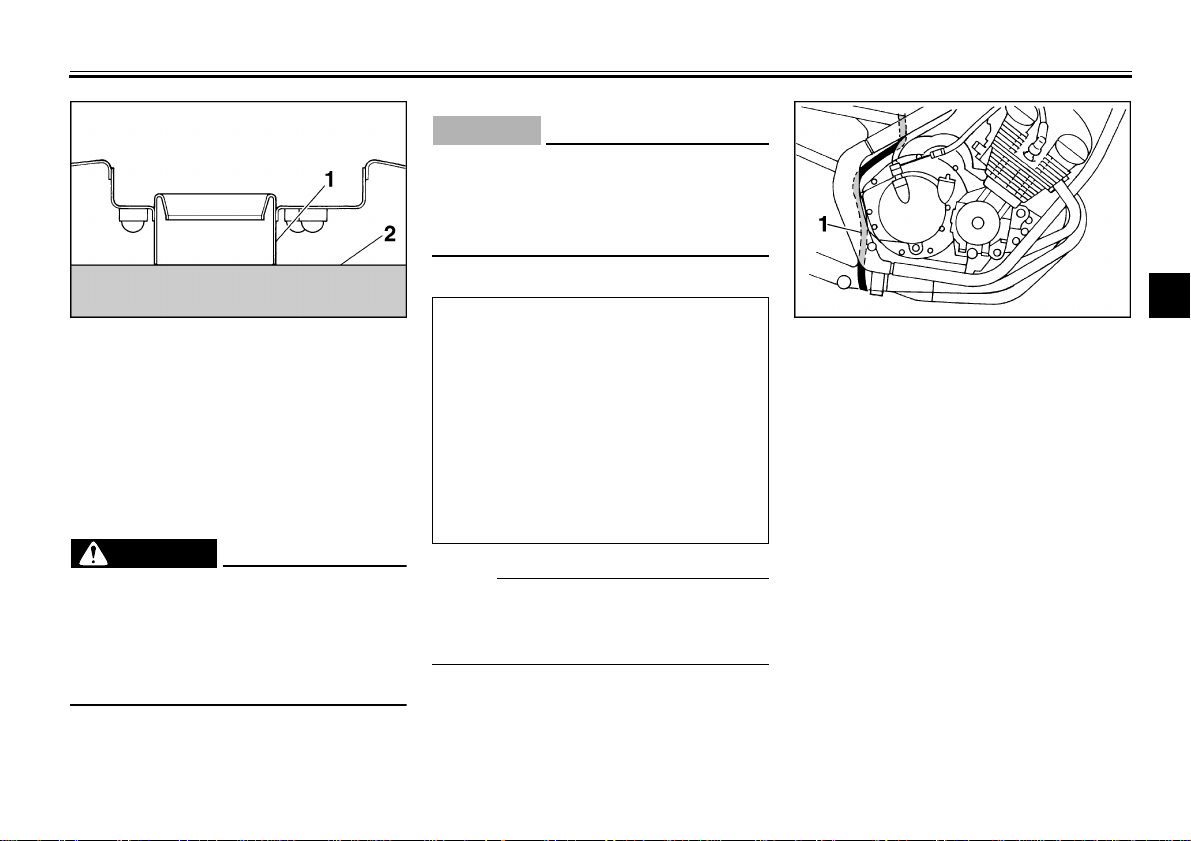
EAU01183
Fuel
Make sure that there is sufficient fuel in
the tank. Fill the fuel tank to the bottom
of the filler tube as shown in the illustra-
tion.
EW000130
W ARNING
@
●
Do not overfill the fuel tank, oth-
erwise it may overflow when the
fuel warms up and expands.
●
Avoid spilling fuel on the hot
engine.
@
EAU00185
CAUTION:
@
Immediately wipe off spilled fuel
with a clean, dry, soft cloth, since
fuel may deteriorate painted surfac-
es or plastic parts.
@
EAU00191
NOTE:
@
If knocking (or pinging) occurs, use
gasoline of a different brand or with a
higher octane grade.
@
EAU00196
Fuel tank breather hose
(for Germany only)
Before operating the motorcycle:
●
Check the fuel tank breather hose
connection.
●
Check the fuel tank breather hose
for cracks or damage, and replace
it if damaged.
●
Make sure that the end of the fuel
tank breather hose is not blocked
and clean it if necessary.
1. Fuel tank filler tube
2. Fuel level
Recommended fuel:
Regular unleaded gasoline with a
research octane number of 91 or
higher
Fuel tank capacity:
Total amount:
17.0 L
Reserve amount:
3.5 L
1. Fuel tank breather hose
INSTRUMENT AND CONTROL FUNCTIONS
3-11
3
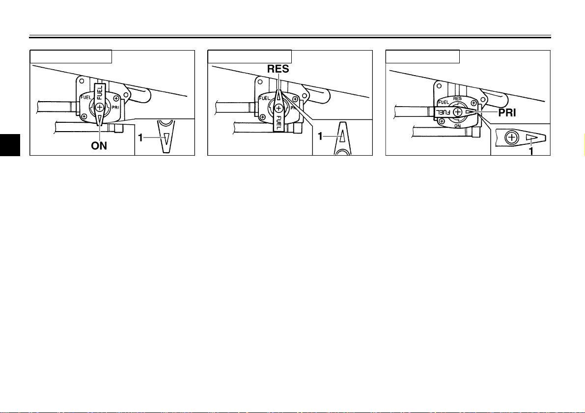
EAU00207
Fuel cock
The fuel cock supplies fuel from the
tank to the carburetors while also filter-
ing it.
The fuel cock lever positions are ex-
plained as follows and shown in the il-
lustrations.
ON
With the fuel cock lever in this position,
fuel flows to the carburetors when the
engine is running. Turn the fuel cock le-
ver to this position when starting the
engine and riding.
RES
This indicates reserve. With the fuel
cock lever in this position, the fuel re-
serve is made available. Quickly turn
the fuel cock lever to this position if you
run out of fuel while riding, otherwise
the engine may stall and will have to be
primed (see “PRI”). After turning the
fuel cock lever to “RES”, refuel as soon
as possible and be sure to turn the fuel
cock lever back to “ON”!
PRI
This indicates prime. With the fuel cock
lever in this position, the engine can be
“primed”. Turn the fuel cock lever to
this position when the engine has been
allowed to run out of fuel. This sends
fuel directly to the carburetors, which
will make starting easier. After the en-
gine has started, be sure to turn the le-
ver to “ON” (or “RES” if you have not
refueled yet).
1. Arrow mark positioned over “ON”
Normal position
1. Arrow mark positioned over “RES”
Reserve position
1. Arrow mark positioned over “PRI”
Prime position
Loading...