


 Loading...
OWNER’S SERVICE MANUAL
YZ250FR
LIT-11626-16-39 |
5UL-28199-10 |

YZ250FR
OWNER’S SERVICE MANUAL
©2002 by Yamaha Motor Corporation, U.S.A. 1st Edition, July 2002
All rights reserved.
Any reprinting or unauthorized use without the written permission of Yamaha Motor Corporation U.S.A. is expressly prohibited.
Printed in Japan
P/N. LIT-11626-16-39

EC020000
INTRODUCTION
Congratulations on your purchase of a Yamaha YZ series. This model is the culmination of Yamaha’s vast experience in the production of pacesetting racing machines. It represents the highest grade of craftsmanship and reliability that have made Yamaha a leader.
This manual explains operation, inspection, basic maintenance and tuning of your machine. If you have any questions about this manual or your machine, please contact your Yamaha dealer.
NOTE:
As improvements are made on this model, some data in this manual may become outdated. If you have any questions, please consult your Yamaha dealer.
 WARNING
PLEASE READ THIS MANUAL CAREFULLY AND COMPLETELY BEFORE OPERATING THIS MACHINE. DO NOT ATTEMPT TO OPERATE THIS MACHINE UNTIL YOU HAVE ATTAINED A SATISFACTORY KNOWLEDGE OF ITS CONTROLS AND OPERATING FEATURES AND UNTIL YOU HAVE BEEN TRAINED IN SAFE AND PROPER RIDING TECHNIQUES. REGULAR INSPECTIONS AND CAREFUL MAINTENANCE, ALONG WITH GOOD RIDING SKILLS, WILL ENSURE THAT YOU SAFETY ENJOY THE CAPABILITIES AND THE RELIABILITY OF THIS MACHINE.


IMPORTANT NOTICE
THIS MACHINE IS DESIGNED STRICTLY FOR COMPETITION USE, ONLY ON A CLOSED COURSE. It is illegal for this machine to be operated on any public street, road, or highway. Off-road use on public lands may also be illegal. Please check local regulations before riding.

 SAFETY INFORMATION
1.THIS MACHINE IS TO BE OPERATED BY AN EXPERIENCED RIDER ONLY. Do not attempt to operate this machine at maximum power until you are totally familiar with its characteristics.
2.THIS MACHINE IS DESIGNED TO BE RIDDEN BY THE OPERATOR ONLY. Do not carry passengers on this machine.
3.ALWAYS WEAR PROTECTIVE APPAREL.
When operating this machine, always wear an approved helmet with goggles or a face shield. Also wear heavy boots, gloves, and protective clothing. Always wear proper fitting clothing that will not be caught in any of the moving parts or controls of the machine.
4.ALWAYS MAINTAIN YOUR MACHINE IN PROPER WORKING ORDER.
For safety and reliability, the machine must be properly maintained. Always perform the pre-operation checks indicated in this manual. Correcting a mechanical problem before you ride may prevent an accident.
5.GASOLINE IS HIGHLY FLAMMABLE. Always turn off the engine while refueling. Take care to not spill any gasoline on the engine or exhaust system. Never refuel in the vicinity of an open flame, or while smoking.

6.GASOLINE CAN CAUSE INJURY.
If you should swallow some gasoline, inhale excess gasoline vapors, or allow any gasoline to get into your eyes, contact a doctor immediately. If any gasoline spills onto your skin or clothing, immediately wash skin areas with soap and water, and change your clothes.
7.ONLY OPERATE THE MACHINE IN AN AREA WITH ADEQUATE VENTILATION.
Never start the engine or let it run for any length of time in an enclosed area. Exhaust fumes are poisonous. These fumes contain carbon monoxide, which by itself is odorless and colorless. Carbon monoxide is a dangerous gas which can cause unconsciousness or can be lethal.
8.PARK THE MACHINE CAREFULLY; TURN OFF THE ENGINE.
Always turn off the engine if you are going to leave the machine. Do not park the machine on a slope or soft ground as it may fall over.
9.THE ENGINE, EXHAUST PIPE, MUFFLER, AND OIL TANK WILL BE VERY HOT AFTER THE ENGINE HAS BEEN RUN.
Be careful not to touch them or to allow any clothing item to contact them during inspection or repair.
10.PROPERLY SECURE THE MACHINE BEFORE TRANSPORTING IT.
When transporting the machine in another vehicle, always be sure it is properly secured and in an upright position and that the fuel cock is in the “OFF” position. Otherwise, fuel may leak out of the carburetor or fuel tank.
EC050000
TO THE NEW OWNER
This manual will provide you with a good basic understanding of features, operation, and basic maintenance and inspection items of this machine. Please read this manual carefully and completely before operating your new machine. If you have any questions regarding the operation or maintenance of your machine, please consult your Yamaha dealer.
NOTE:
This manual should be considered a permanent part of this machine and should remain with it even if the machine is subsequently sold.
EC060000
NOTICE
Some data in this manual may become outdated due to improvements made to this model in the future. If there is any question you have regarding this manual or your machine, please consult your Yamaha dealer.
EC070001
F.I.M. MACHINE WEIGHTS:
Weights of machines without fuel
The minimum weights for motocross machines are:
for the class 125 cc |
....................... minimum |
|
88 kg (194 lb) |
for the class 250 cc ....................... |
minimum |
|
98 kg (216 lb) |
for the class 500 cc ....................... |
minimum |
|
102 kg (225 lb) |
In modifying your machine (e.g., for weight reduction), take note of the above limits of weight.
EC080000
HOW TO USE
THIS MANUAL
EC081000
PARTICULARLY IMPORTANT INFORMATION
The Safety Alert Symbol means ATTENTION! BECOME ALERT! YOUR SAFETY IS INVOLVED!
 WARNING
Failure to follow WARNING instructions could result in severe injury or death to the machine operator, a bystander, or a person inspecting or repairing the machine.

 CAUTION:

A CAUTION indicates special precautions that must be taken to avoid damage to the machine.
NOTE:
A NOTE provides key information to make procedures easier or clearer.
EC082000
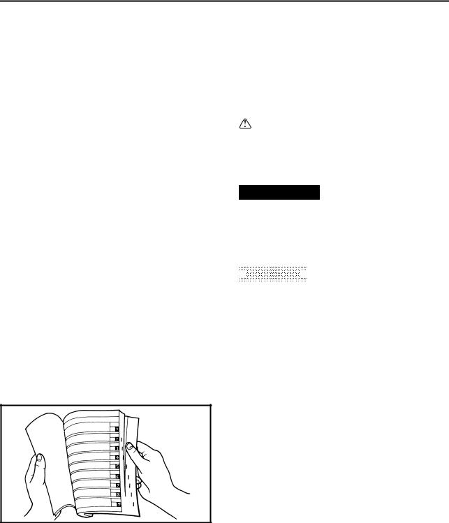
FINDING THE REQUIRED PAGE
1.This manual consists of seven chapters; “General information”, “Specifications”, “Regular inspection and adjustments”, “Engine”, “Chassis”, “Electrical” and “Tuning”.
2.The table of contents is at the beginning of the manual. Look over the general layout of the book before finding then required chapter and item.
Bend the book at its edge, as shown, to find the required fore edge symbol mark and go to a page for required item and description.
EC083000
MANUAL FORMAT
All of the procedures in this manual are organized in a sequential, step-by-step format. The information has been complied to provide the mechanic with an easy to read, handy reference that contains comprehensive explanations of all disassembly, repair, assembly, and inspection operations.
In this revised format, the condition of a faulty component will precede an arrow symbol and the course of action required will follow the symbol, e.g.,
●Bearings
Pitting/damage → Replace.
EC084002
HOW TO READ DESCRIPTIONS
To help identify parts and clarify procedure steps, there are exploded diagrams at the start of each removal and disassembly section.
1.An easy-to-see exploded diagram 1 is provided for removal and disassembly jobs.
2.Numbers 2 are given in the order of the jobs in the exploded diagram. A number that is enclosed by a circle indicates a disassembly step.
3.An explanation of jobs and notes is presented in an easy-to-read way by the use of symbol marks 3. The meanings of the symbol marks are given on the next page.
4.A job instruction chart 4 accompanies the exploded diagram, providing the order of jobs, names of parts, notes in jobs, etc.
5.Extent of removal 5 is provided in the job instruction chart to save the trouble of an unnecessary removal job.
6.For jobs requiring more information, the step-by-step format supplements 6 are given in addition to the exploded diagram and job instruction chart.
1 |
2 |
|
GEN |
SPEC |
|
INFO |
|
|
|
|
|
3 |
4 |
|
INSP |
ENG |
|
ADJ |
|
|
|
|
|
5 |
6 |
|
CHAS |
ELEC – |
+ |
7 |
8 |
|
T U N |
|
|
9 |
0 |
|
A |
B |
|
|
T |
|
|
. |
|
|
R |
|
|
. |
|
C |
D |
|
E |
F |
|
E |
M |
|
G |
H |
|
B |
M |
|
I |
J |
|
ILLUSTRATED SYMBOLS (Refer to the illustration)
Illustrated symbols 1 to 7 are designed as thumb tabs to indicate the chapter’s number and content.
1 General information
2 Specifications
3 Regular inspection and adjustments
4 Engine
5 Chassis
6 Electrical
7 Tuning
Illustrated symbols 8 to D are used to identify the specifications appearing in the text.
8 With engine mounted
9 Special tool
0 Filling fluid A Lubricant B Tightening
C Specified value, Service limit
D Resistance (Ω), Voltage (V), Electric current (A)
Illustrated symbols E to H in the exploded diagrams indicate grade of lubricant and location of lubrication point.
E Apply engine oil
F Apply molybdenum disulfide oil
G Apply lightweight lithium-soap base grease H Apply molybdenum disulfide grease
Illustrated symbols I to J in the exploded diagrams indicate where to apply a locking agent and where to install new parts.
I Apply locking agent (LOCTITE®)
J Use new one

MEMO
EC090000
INDEX
GENERAL INFORMATION |
GEN |
1 |
|
INFO |
SPECIFICATIONS
SPEC 2
REGULAR INSPECTION AND ADJUSTMENTS
INSP 3 ADJ
ENGINE
ENG 4
CHASSIS
CHAS 5
– +
ELECTRICAL
ELEC 6
TUNING
TUN 7

EC0A0000
CONTENTS
CHAPTER 1
GENERAL INFORMATION
DESCRIPTION .......................................... |
1-1 |
MACHINE IDENTIFICATION .................... |
1-2 |
IMPORTANT INFORMATION ................... |
1-3 |
CHECKING OF CONNECTION ................. |
1-6 |
SPECIAL TOOLS ...................................... |
1-7 |
CONTROL FUNCTIONS ......................... |
1-10 |
FUEL ....................................................... |
1-13 |
STARTING AND BREAK-IN ................... |
1-14 |
TORQUE-CHECK POINTS ..................... |
1-18 |
CLEANING AND STORAGE ................... |
1-19 |
CHAPTER 2
SPECIFICATIONS
GENERAL SPECIFICATIONS .................. |
2-1 |
MAINTENANCE SPECIFICATIONS ......... |
2-4 |
GENERAL TORQUE |
|
SPECIFICATIONS ................................... |
2-17 |
DEFINITION OF UNITS ........................... |
2-17 |
CABLE ROUTING DIAGRAM ................. |
2-18 |
CHAPTER 3
REGULAR INSPECTION AND
ADJUSTMENTS
MAINTENANCE INTERVALS ................... |
3-1 |
PRE-OPERATION INSPECTION |
|
AND MAINTENANCE ................................ |
3-4 |
ENGINE ..................................................... |
3-5 |
CHASSIS ................................................. |
3-24 |
ELECTRICAL .......................................... |
3-45 |

CHAPTER 4
ENGINE
SEAT, FUEL TANK |
|
AND SIDE COVERS ................................. |
4-1 |
EXHAUST PIPE AND SILENCER ............ |
4-3 |
RADIATOR ................................................ |
4-5 |
CARBURETOR ......................................... |
4-8 |
CAMSHAFTS .......................................... |
4-21 |
CYLINDER HEAD ................................... |
4-30 |
VALVES AND VALVE SPRINGS ........... |
4-33 |
CYLINDER AND PISTON ....................... |
4-42 |
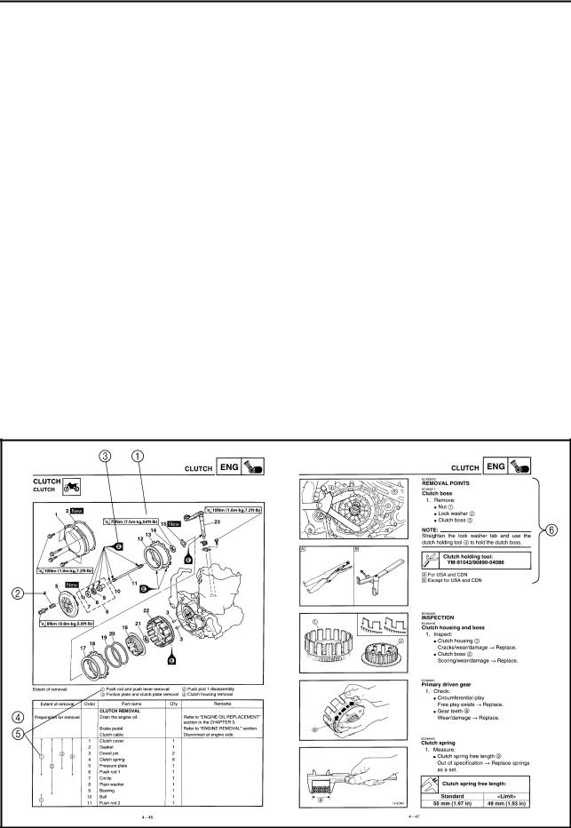
CLUTCH .................................................. |
4-49 |
OIL FILTER ELEMENT, WATER PUMP |
|
AND RIGHT CRANKCASE COVER ...... |
4-56 |
BALANCER ............................................. |
4-63 |
OIL PUMP ............................................... |
4-66 |
KICK SHAFT AND SHIFT SHAFT .......... |
4-71 |
CDI MAGNETO ....................................... |
4-78 |
ENGINE REMOVAL ................................ |
4-82 |
CRANKCASE AND CRANKSHAFT ....... |
4-87 |
TRANSMISSION, SHIFT CAM |
|
AND SHIFT FORK .................................. |
4-96 |
CHAPTER 5
CHASSIS
FRONT WHEEL AND REAR WHEEL |
....... 5-1 |
FRONT BRAKE AND REAR BRAKE ..... |
5-10 |
FRONT FORK ......................................... |
5-26 |
HANDLEBAR .......................................... |
5-39 |
STEERING .............................................. |
5-45 |
SWINGARM ............................................ |
5-50 |
REAR SHOCK ABSORBER ................... |
5-58 |

CHAPTER 6
ELECTRICAL
ELECTRICAL COMPONENTS |
|
AND WIRING DIAGRAM ........................... |
6-1 |
MAP-CONTROLLED CDI UNIT ................ |
6-2 |
IGNITION SYSTEM ................................... |
6-3 |
THROTTLE POSITION SENSOR |
|
SYSTEM .................................................... |
6-7 |
|
CHAPTER 7 |
|
TUNING |
ENGINE ..................................................... |
7-1 |
CHASSIS ................................................. |
7-11 |
GEN
DESCRIPTION INFO
EC100000
GENERAL INFORMATION
EC110000
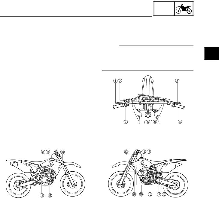
DESCRIPTION
1 Clutch lever
2 Hot starter lever
3 Front brake lever
4 Throttle grip
5 Radiator cap
6 Fuel tank cap
7 Engine stop switch
8 Kickstarter crank
9 Fuel tank
0 Radiator
A Coolant drain bolt B Rear brake pedal C Valve joint
D Fuel cock
E Cold starter knob F Drive chain
G Air filter H Shift pedal I Dipstick J Front fork
NOTE:
●The machine you have purchased may differ slightly from those shown in the following.
●Designs and specifications are subject to change without notice.
1 |
1 - 1
MACHINE IDENTIFICATION
EC120001
GEN  INFO
INFO 

MACHINE IDENTIFICATION
There are two significant reasons for knowing the serial number of your machine:
1.When ordering parts, you can give the number to your Yamaha dealer for positive identification of the model you own.
2.If your machine is stolen, the authorities will need the number to search for and identify your machine.
EC121001
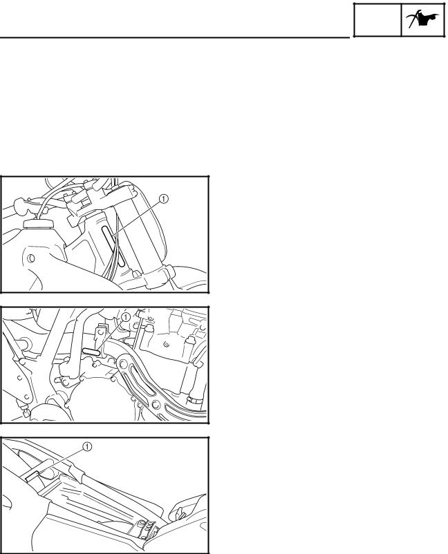
VEHICLE IDENTIFICATION NUMBER
The vehicle identification number 1 is stamped on the right of the steering head pipe.
EC123001
ENGINE SERIAL NUMBER
The engine serial number 1 is stamped into the elevated part of the right-side of the engine.
EC124000
MODEL LABEL
The model label 1 is affixed to the frame under the rider’s seat. This information will be needed to order spare parts.
1 - 2
GEN
IMPORTANT INFORMATION INFO
EC130000
IMPORTANT INFORMATION
EC131010
PREPARATION FOR REMOVAL AND
DISASSEMBLY
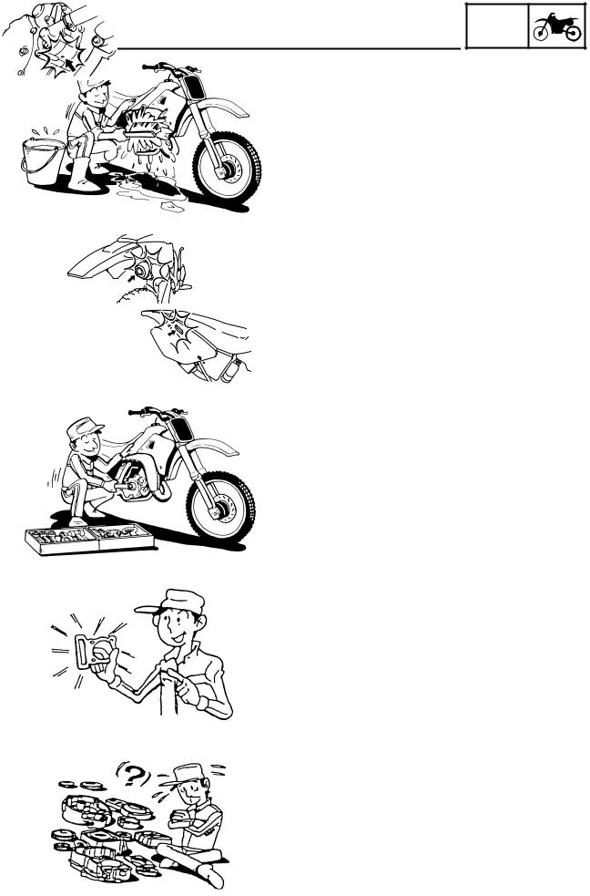
1.Remove all dirt, mud, dust, and foreign material before removal and disassembly.
When washing the machine with high pressured water, cover the parts follows.
●Silencer exhaust port
●Side cover air intake port
●Water pump housing hole at the bottom
●Drain hole on the cylinder head (right side)
2.Use proper tools and cleaning equipment. Refer to “SPECIAL TOOLS” section.
3.When disassembling the machine, keep mated parts together. They include gears, cylinders, pistons, and other mated parts that have been “mated” through normal wear. Mated parts must be reused as an assembly or replaced.
4.During the machine disassembly, clean all parts and place them in trays in the order of disassembly. This will speed up assembly time and help assure that all parts are correctly reinstalled.
5.Keep away from fire.
1 - 3
IMPORTANT INFORMATION
EC132000
GEN  INFO
INFO 

ALL REPLACEMENT PARTS
1.We recommend to use Yamaha genuine parts for all replacements. Use oil and/or grease recommended by Yamaha for assembly and adjustment.
EC133000
GASKETS, OIL SEALS AND O-RINGS
1.All gaskets, oil seals, and O-rings should be replaced when an engine is overhauled. All gasket surfaces, oil seal lips, and O-rings must be cleaned.
2.Properly oil all mating parts and bearings during reassembly. Apply grease to the oil seal lips.
EC134000
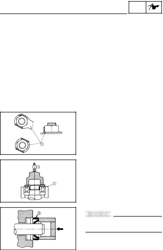
LOCK WASHERS/PLATES AND COTTER PINS
1.All lock washers/plates 1 and cotter pins must be replaced when they are removed. Lock tab(s) should be bent along the bolt or nut flat(s) after the bolt or nut has been properly tightened.
EC135001
BEARINGS AND OIL SEALS
1.Install the bearing(s) 1 and oil seal(s) 2 with their manufacturer’s marks or numbers facing outward. (In other words, the stamped letters must be on the side exposed to view.) When installing oil seal(s), apply a light coating of lightweight lithium base grease to the seal lip(s). Oil the bearings liberally when installing.
 CAUTION:
Do not use compressed air to spin the bearings dry. This causes damage to the bearing surfaces.
1 - 4
GEN
IMPORTANT INFORMATION INFO
EC136000
CIRCLIPS
1.All circlips should be inspected carefully before reassembly. Always replace piston pin clips after one use. Replace distorted circlips. When installing a circlip 1, make sure that the sharp-edged corner 2 is positioned opposite to the thrust
3 it receives. See the sectional view.
4 Shaft
1 - 5
GEN
CHECKING OF CONNECTION INFO
EC1C0001
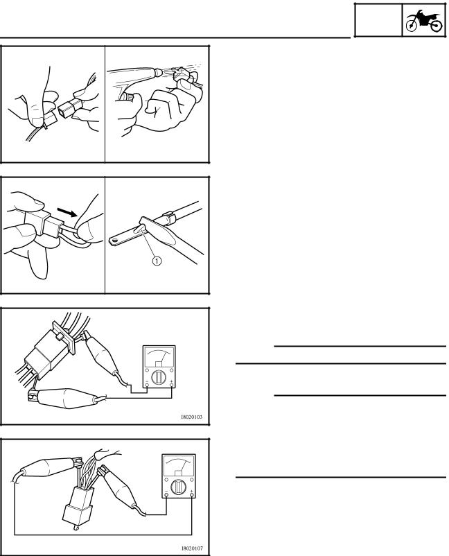
CHECKING OF CONNECTION
Dealing with stains, rust, moisture, etc. on the connector.
1.Disconnect:
●Connector
2.Dry each terminal with an air blower.
3.Connect and disconnect the connector two or three times.
4.Pull the lead to check that it will not come off.
5.If the terminal comes off, bend up the pin 1 and reinsert the terminal into the connector.
6.Connect:
●Connector
NOTE:
The two connectors “click” together.
7. Check for continuity with a tester.
NOTE:
●If there in no continuity, clean the terminals.
●Be sure to perform the steps 1 to 7 listed above when checking the wireharness.
●For a field remedy, use a contact revitalizer available on the market.
●Use the tester on the connector as shown.
1 - 6
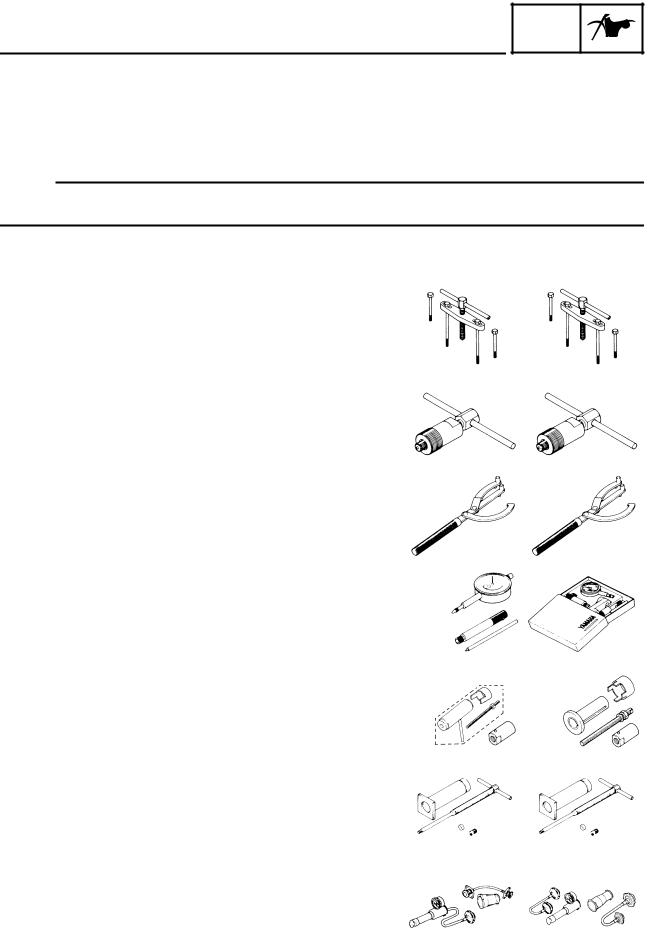
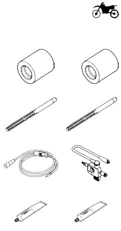
SPECIAL TOOLS
SPECIAL TOOLS
GEN  INFO
INFO 

The proper special tools are necessary for complete and accurate tune-up and assembly. Using the correct special tool will help prevent damage caused by the use of improper tools or improvised techniques. The shape and part number used for the special tool differ by country, so two types are provided. Refer to the list provided to avoid errors when placing an order.
NOTE:
●For U.S.A. and Canada, use part number starting with “YM-”, “YU-” or “ACC-”.
●For others, use part number starting with “90890-”.
Part number |
Tool name/How to use |
|
Illustration |
|
|
|
|
|
|
YU-1135-A, 90890-01135 |
Crankcase separating tool |
YU-1135-A |
|
90890-01135 |
|
These tool is used to remove the crankshaft from |
|
|
|
|
either case. |
|
|
|
|
|
|
|
|
YM-1189, 90890-01189 |
Flywheel puller |
YM-1189 |
|
90890-01189 |
|
This tool is used to remove the flywheel magneto. |
|
|
|
|
|
|
|
|
YU-1235, 90890-01235 |
Rotor holding tool |
YU-1235 |
|
90890-01235 |
|
This tool is used when loosening or tightening the fly- |
|
|
|
|
wheel magneto securing nut. |
|
|
|
|
|
|
|
|
YU-3097, 90890-01252 |
Dial gauge and stand |
YU-3097 |
|
90890-01252 |
YU-1256 |
Stand |
YU-1256 |
|
|
|
|
|
||
|
These tools are used to check each part for runout or |
|
|
|
|
bent. |
|
|
|
|
|
|
|
|
|
Crankshaft installing tool |
YU-90050 |
|
90890-01274 |
YU-90050, 90890-01274 |
Crankshaft installing pot |
YU-90063 |
|
90890-01275 |
YU-91044 |
|
90890-01278 |
||
YU-90050, 90890-01275 |
Crankshaft installing bolt |
|
||
|
|
90890-04081 |
||
YU-91044, 90890-04081 |
Spacer (crankshaft installer) |
|
|
|
YU-90063, 90890-01278 |
Adapter (M12) |
|
|
|
|
These tools are used to install the crankshaft. |
|
|
|
|
|
|
|
|
YU-1304, 90890-01304 |
Piston pin puller set |
YU-1304 |
|
90890-01304 |
|
This tool is used to remove the piston pin. |
|
|
|
|
|
|
|
|
YU-24460-01, 90890-01325 |
Radiator cap tester |
YU-24460-01 |
|
90890-01325 |
YU-33984, 90890-01352 |
Radiator cap tester adapter |
YU-33984 |
|
90890-01352 |
|
|
|
||
|
These tools are used for checking the cooling sys- |
|
|
|
|
tem. |
|
|
|
|
|
|
|
|
|
1 - 7 |
|
|
|
|
|
|
|
|
|
|
|
|
SPECIAL TOOLS |
|
GEN |
|
|
||
|
|
INFO |
|
|
|||
|
|
|
|
|
|
|
|
|
|
|
|
|
|||
Part number |
Tool name/How to use |
Illustration |
|
||||
|
|
|
|
|
|||
YU-33975, 90890-01403 |
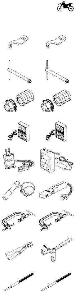
Steering nut wrench |
YU-33975 |
|
|
90890-01403 |
|
|
|
This tool is used when tighten the steering ring nut to |
|
|
|
|
|
|
|
specification. |
|
|
|
|
|
|
|
|
|
|
|
|
||
YM-1423, 90890-01423 |
Damper rod holder |
YM-1423 |
|
|
90890-01423 |
|
|
|
Use this tool to remove and install the damper rod. |
|
|
|
|
|
|
|
|
|
|
|
|
||
YM-01442, 90890-01442 |
Fork seal driver |
YM-01442 |
|
|
90890-01442 |
|
|
|
This tool is used when install the fork oil seal. |
|
|
|
|
|
|
|
|
|
|
|
|
||
YU-3112-C, 90890-03112 |
Pocket tester |
YU-3112-C |
|
|
90890-03112 |
|
|
|
Use this tool to inspect the coil resistance, output |
|
|
|
|
|
|
|
voltage and amperage. |
|
|
|
|
|
|
|
|
|
|
|
|
||
YU-8036-B |
Inductive tachometer |
YU-8036-B |
|
|
90890-03113 |
|
|
90890-03113 |
Engine tachometer |
|
|
|
|
|
|
|
This tool is needed for observing engine rpm. |
|
|
|
|
|
|
|
|
|
|
|
|
||
YM-33277-A, 90890-03141 |
Timing light |
YM-33277-A |
|
|
90890-03141 |
|
|
|
This tool is necessary for checking ignition timing. |
|
|
|
|
|
|
|
|
|
|
|
|
||
YM-4019, 90890-04019 |
Valve spring compressor |
YM-4019 |
|
|
90890-04019 |
|
|
|
This tool is needed to remove and install the valve |
|
|
|
|
|
|
|
assemblies. |
|
|
|
|
|
|
|
|
|
|
|
|
||
YM-91042, 90890-04086 |
Clutch holding tool |
YM-91042 |
|
|
90890-04086 |
|
|
|
This tool is used to hold the clutch when removing or |
|
|
|
|
|
|
|
installing the clutch boss securing nut. |
|
|
|
|
|
|
|
|
|
|
|
|
||
YM-4111, 90890-04111 |
Valve guide remover |
YM-4111 |
|
|
90890-04111 |
|
|
YM-4116, 90890-04116 |
Intake 4.0 mm (0.16 in) |
YM-4116 |
|
90890-04116 |
|
||
|
Exhaust 4.5 mm (0.18 in) |
|
|
|
|
|
|
|
This tool is needed to remove and install the valve |
|
|
|
|
|
|
|
guide. |
|
|
|
|
|
|
|
|
|
|
|
|
|
|
|
1 - 8 |
|
|
|
|
|
|
|
|
|
|
|
|
|
|
|
SPECIAL TOOLS |
|
GEN |
|
|
||
|
|
INFO |
|
|
|||
|
|
|
|
|
|
|
|
|
|
|
|
|
|||
Part number |
Tool name/How to use |
Illustration |
|
||||
|
|
|
|
|
|||
YM-4112, 90890-04112 |
Valve guide installer |
YM-4112 |
|
|
90890-04112 |
|
|
YM-4117, 90890-04117 |
Intake 4.0 mm (0.16 in) |
YM-4117 |
|
90890-04117 |
|
||
|
Exhaust 4.5 mm (0.18 in) |
|
|
|
|
|
|
|
This tool is needed to install the valve guide. |
|
|
|
|
|
|
|
|
|
|
|
|
||
YM-4113, 90890-04113 |
Valve guide reamer |
YM-4113 |
|
|
90890-04113 |
|
|
YM-4118, 90890-04118 |
Intake 4.0 mm (0.16 in) |
YM-4118 |
|
90890-04118 |
|
||
|
Exhaust 4.5 mm (0.18 in) |
|
|
|
|
|
|
|
This tool is needed to rebore the new valve guide. |
|
|
|
|
|
|
|
|
|
|
|
|
||
YM-34487 |
Dynamic spark tester |
YM-34487 |
|
|
90890-06754 |
|
|
90890-06754 |
Ignition checker |
|
|
|
|
|
|
|
This instrument is necessary for checking the ignition |
|
|
|
|
|
|
|
system components. |
|
|
|
|
|
|
|
|
|
|
|
|
||
ACC-QUICK-GS-KT |
Quick gasket |
ACC-QUICK-GS-KT |
|
|
90890-85505 |
|
|
90890-85505 |
YAMAHA Bond No. 1215 |
|
|
|
|
|
|
|
This sealant (Bond) is used for crankcase mating |
|
|
|
|
|
|
|
surface, etc. |
|
|
|
|
|
|
|
|
|
|
|
|
|
|
1 - 9
GEN
CONTROL FUNCTIONS INFO
EC150000
CONTROL FUNCTIONS
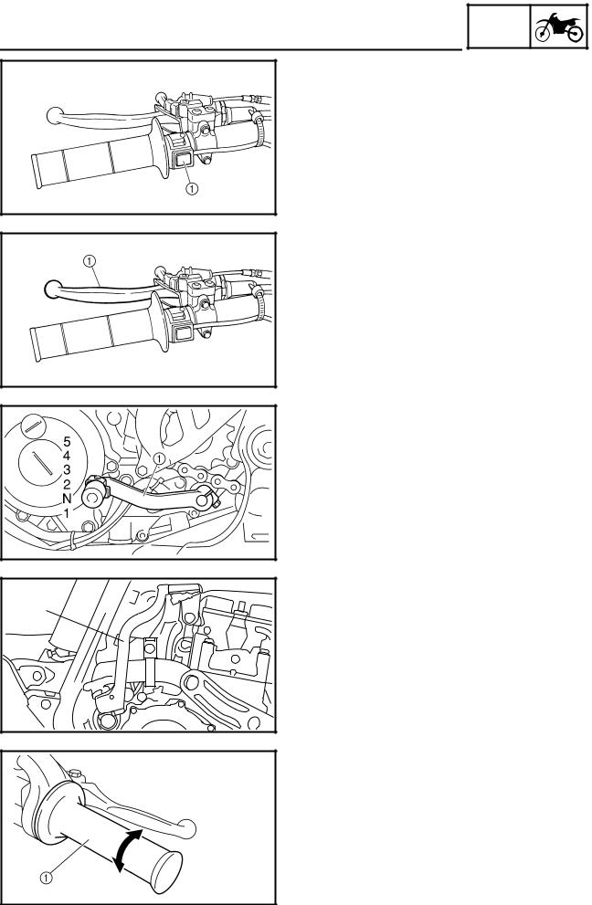
ENGINE STOP SWITCH
The engine stop switch 1 is located on the left handlebar. Continue pushing the engine stop switch till the engine comes to a stop.
EC152000
CLUTCH LEVER
The clutch lever 1 is located on the left handlebar; it disengages or engages the clutch. Pull the clutch lever to the handlebar to disengage the clutch, and release the lever to engage the clutch. The lever should be pulled rapidly and released slowly for smooth starts.
EC153000
SHIFT PEDAL
The gear ratios of the constant-mesh 5 speed transmission are ideally spaced. The gears can be shifted by using the shift pedal 1 on the left side of the engine.
1 |
KICKSTARTER CRANK
Rotate the kickstarter crank 1 away from the engine. Push the starter down lightly with your foot until the gears engage, then kick smoothly and forcefully to start the engine. This model has a primary kickstarter crank so the engine can be started in any gear if the clutch is disengaged. In normal practices, however, shift to neutral before starting.
EC155001
THROTTLE GRIP
The throttle grip 1 is located on the right handlebar; it accelerates or decelerates the engine. For acceleration, turn the grip toward you; for deceleration, turn it away from you.
1 - 10
GEN
CONTROL FUNCTIONS INFO
EC156000
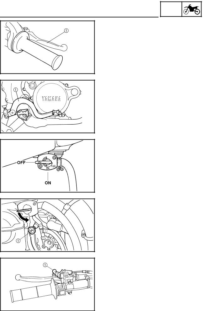
FRONT BRAKE LEVER
The front brake lever 1 is located on the right handlebar. Pull it toward the handlebar to activate the front brake.
EC157000
REAR BRAKE PEDAL
The rear brake pedal 1 is located on the right side of the machine. Press down on the brake pedal to activate the rear brake.
EC158001
FUEL COCK
The fuel cock supplies fuel from the tank to carburetor while filtering the fuel. The fuel cock has the two positions:
OFF:With the lever in this position, fuel will not flow. Always return the lever to this position when the engine is not running.
ON: With the lever in this position, fuel flows to the carburetor. Normal riding is done with the lever in this position.
COLD STARTER KNOB
When cold, the engine requires a richer air-fuel mixture for starting. A separate starter circuit, which is controlled by the cold starter knob 1, supplies this mixture. Pull the cold starter knob out to open the circuit for starting. When the engine has warmed up, push it in to close the circuit.
HOT STARTER LEVER
The hot starter lever 1 is used when starting a warm engine.
Use the hot starter lever when starting the engine again immediately after it was stopped (the engine is still warm). Pulling the hot starter lever injects secondary air to thin the air-fuel mixture temporarily, allowing the engine to be started more easily.
1 - 11
GEN
CONTROL FUNCTIONS INFO
EC15R001
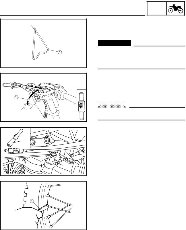
DETACHABLE SIDESTAND
This sidestand 1 is used to support only the machine when standing or transporting it.
 WARNING
●Never apply additional force to the sidestand.
●Remove this sidestand before starting out.
EC15F000
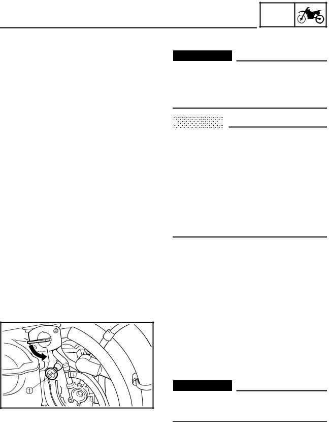
VALVE JOINT
This valve joint 1 prevents fuel from flowing out and is installed to the fuel tank breather hose.
 CAUTION:
In this installation, make sure the arrow faces the fuel tank and also downward.
1 |
1 |
SPARK PLUG WRENCH
This spark plug wrench 1 is used to remove and install the spark plug.
NIPPLE WRENCH
This nipple wrench 1 is used to tighten the spoke.
1 - 12
FUEL
FUEL
GEN  INFO
INFO 

Always use the recommended fuel as stated below. Also, be sure to use new gasoline the day of a race.
Recommended fuel: Except for ZA:
Premium unleaded gasoline only with a research octane number of 95 or higher.
For ZA:
Premium gasoline
 CAUTION:
Use only unleaded gasoline. The use of leaded gasoline will cause severe damage to the engine internal parts such as valves, piston rings, and exhaust system, etc.
NOTE:
If knocking or pinging occurs, use a different brand of gasoline or higher octane grade.
 WARNING
●For refueling, be sure to stop the engine and use enough care not to spill any fuel. Also be sure to avoid refueling close to a fire.
●Refuel after the engine, exhaust pipe, etc. have cooled off.
1 - 13
GEN
STARTING AND BREAK-IN INFO
STARTING AND BREAK-IN
 WARNING
Never start or run the engine in a closed area. The exhaust fumes are poisonous; they can cause loss of consciousness and death in a very short time. Always operate the machine in a well-ventilated area.
 CAUTION:
●The carburetor on this machine has a built-in accelerator pump. Therefore, when starting the engine, do not operate the throttle or the spark plug will foul.
●Unlike a two-stroke engine, this engine cannot be kick started when the throttle is open because the kick starter may kick back. Also, if the throttle is open the air/ fuel mixture may be too lean for the engine to start.
●Before starting the machine, perform the checks in the pre-operation check list.
STARTING A COLD ENGINE
1.Inspect the coolant level.
2.Turn the fuel cock to “ON”.
3.Shift the transmission into neutral.
4.Fully open the cold starter knob 1.
5.Kick the kickstarter crank.
 WARNING
Do not open the throttle while kicking the kickstarter crank. Otherwise, the kickstarter may kick back.
1 - 14
Loading...