


Xylem H-310 User Manual

Model
H-310
Owner's Manual
NOTICE
This product embodies technology that is confidential and proprietary technology of DESIGN
ANALYSIS ASSOCIATES, INC., and which is protected by United States copyright laws and
international copyright treaty provisions, and/or by contract and applicable laws of trade secrecy.
These include all Software, Printed Circuit Board Artwork, Schematic Diagrams, and Technologies
applied therein. The enclosure encasing the electronics of this instrument may not be opened without
written consent of DESIGN ANALYSIS ASSOCIATES, INC., and any attempt to do so without
such written authorization constitutes a breach of contract and will also void any applicable warranty
for the product.
Document Number: H310
Document Authors: Terrell Fletcher
Revision: 2.7
75 West 100 South
Logan, UT 84321 USA
Phone: (435) 753-2212
Fax: (435) 753-7669


Table of Contents
User Agreement/WATERLOG® Warranty . . . . . . . . . . . . . . . . . . . . . . . . . . . . . . . . . . . . . . . W-1
Preface: A Message from the H-310 Design Team . . . . . . . . . . . . . . . . . . . . . . . . . . . . . . . P-1
Chapter 1 Unpacking the H-310
1.1 Unpacking the H-310 . . . . . . . . . . . . . . . . . . . . . . . . . . . . . . . . . . . . . . . . . . . . . . . . . . . . 1-1
1.2 Checking the Model Number . . . . . . . . . . . . . . . . . . . . . . . . . . . . . . . . . . . . . . . . . . . . . . 1-2
1.3 Testing the System . . . . . . . . . . . . . . . . . . . . . . . . . . . . . . . . . . . . . . . . . . . . . . . . . . . . . . 1-2
Chapter 2 Installation
2.1 Installing the W
2.1.1 Sensor Deployment . . . . . . . . . . . . . . . . . . . . . . . . . . . . . . . . . . . . . . . . . . . . . . . . . 2-1
2.1.2 Environmental Concerns . . . . . . . . . . . . . . . . . . . . . . . . . . . . . . . . . . . . . . . . . . . . . 2-3
2.3 Range of Stage . . . . . . . . . . . . . . . . . . . . . . . . . . . . . . . . . . . . . . . . . . . . . . . . . . . . . . . . . 2-3
2.4 Connecting the Hook-up Cable . . . . . . . . . . . . . . . . . . . . . . . . . . . . . . . . . . . . . . . . . . . . 2-4
2.5 Connecting Your Data Recorder . . . . . . . . . . . . . . . . . . . . . . . . . . . . . . . . . . . . . . . . . . . 2-6
Chapter 3 Operation
3.1 Operation . . . . . . . . . . . . . . . . . . . . . . . . . . . . . . . . . . . . . . . . . . . . . . . . . . . . . . . . . . . . . 3-1
3.2 Reading Data from the H-310 . . . . . . . . . . . . . . . . . . . . . . . . . . . . . . . . . . . . . . . . . . . . . 3-2
Chapter 4 Maintenance
4.1 Maintenance . . . . . . . . . . . . . . . . . . . . . . . . . . . . . . . . . . . . . . . . . . . . . . . . . . . . . . . . . . . 4-1
4.2 H-305 Maintenance Procedure . . . . . . . . . . . . . . . . . . . . . . . . . . . . . . . . . . . . . . . . . . . . . 4-1
4.3 Cleaning the Port Screens . . . . . . . . . . . . . . . . . . . . . . . . . . . . . . . . . . . . . . . . . . . . . . . . 4-2
4.4 Maintaining Desiccant Packs . . . . . . . . . . . . . . . . . . . . . . . . . . . . . . . . . . . . . . . . . . . . . . 4-4
4.5 Trouble Shooting . . . . . . . . . . . . . . . . . . . . . . . . . . . . . . . . . . . . . . . . . . . . . . . . . . . . . . . 4-4
Appendix A - Specifications . . . . . . . . . . . . . . . . . . . . . . . . . . . . . . . . . . . . . . . . . . . . . . . . . A-1
ATERLOG
®
H-310 and the H-305 . . . . . . . . . . . . . . . . . . . . . . . . . . . . . 2-1
Appendix B - Key to the Model Ordering System . . . . . . . . . . . . . . . . . . . . . . . . . . . . . . . . . B-1
Appendix C - SDI-12 Command and Response Protocol
C.1 SDI-12 Command and Response Protocol . . . . . . . . . . . . . . . . . . . . . . . . . . . . . . . . . . . C-1
C.2 Initiate Measurement Command . . . . . . . . . . . . . . . . . . . . . . . . . . . . . . . . . . . . . . . . . . . C-2
C.3 Initiate Verify Command . . . . . . . . . . . . . . . . . . . . . . . . . . . . . . . . . . . . . . . . . . . . . . . . . C-3
C.4 Send Data Command . . . . . . . . . . . . . . . . . . . . . . . . . . . . . . . . . . . . . . . . . . . . . . . . . . . . C-3
C.5 Send Acknowledge Command . . . . . . . . . . . . . . . . . . . . . . . . . . . . . . . . . . . . . . . . . . . . C-4
C.6 Send Identification Command . . . . . . . . . . . . . . . . . . . . . . . . . . . . . . . . . . . . . . . . . . . . . C-5

Appendix D - H-310 Extended Commands
D.1 Change Sensor Address . . . . . . . . . . . . . . . . . . . . . . . . . . . . . . . . . . . . . . . . . . . . . . . . . . D-1
D.2 Zero Offset Command . . . . . . . . . . . . . . . . . . . . . . . . . . . . . . . . . . . . . . . . . . . . . . . . . . . D-2
D.3 Write "User Units Slope" Command . . . . . . . . . . . . . . . . . . . . . . . . . . . . . . . . . . . . . . . D-3
D.4 Write "User Units Offset" Command . . . . . . . . . . . . . . . . . . . . . . . . . . . . . . . . . . . . . . . D-4
D.5 Read "User Units Slope" Command . . . . . . . . . . . . . . . . . . . . . . . . . . . . . . . . . . . . . . . . D-5
D.6 Read "User Units Offset" Command . . . . . . . . . . . . . . . . . . . . . . . . . . . . . . . . . . . . . . . D-5
D.7 Change Sensor Output Mode . . . . . . . . . . . . . . . . . . . . . . . . . . . . . . . . . . . . . . . . . . . . . D-6
D.7.1 Query Sensor Speed Command . . . . . . . . . . . . . . . . . . . . . . . . . . . . . . . . . . . . . . D-6
D.7.2 Set Sensor Measurement Speed Fast . . . . . . . . . . . . . . . . . . . . . . . . . . . . . . . . . . . D-7
D.7.3 Set Sensor Measurement Speed Slow . . . . . . . . . . . . . . . . . . . . . . . . . . . . . . . . . . D-7

User Agreement/
WATERLOG® Warranty
1. NATURE OF THE PRODUCT
This agreement accompanies a pressure measuring system comprising micro-coded circuitry and
other electronic equipment sealed in an enclosed housing, and packaged together with written
instructional materials. The packaged electronic circuitry and instructional materials herein are
collectively referred to as the “PRODUCT.” The PRODUCT is made available from DESIGN
ANALYSIS ASSOCIATES, INC., of 75 West 100 South, Logan, Utah 84321 (hereinafter
referred to as “DESIGN ANALYSIS”), and contains information and embodies technology that
is confidential and proprietary to DESIGN ANALYSIS, and the availability and use of the
PRODUCT is extended to you, the USER, solely on the basis of the terms of agreement which
follow.
2. ACKNOWLEDGMENTS BY USER
Opening the package which encloses the accompanying PRODUCT indicates your acceptance of
the terms and conditions of this agreement and constitutes an acknowledgment by you of the
confidential and proprietary nature of the rights of DESIGN ANALYSIS in the PRODUCT.
3. DUTIES OF YOU, THE USER
In consideration for the access to and use of the PRODUCT extended to you by DESIGN
ANALYSIS and to protect the confidential and proprietary information of DESIGN ANALYSIS,
USER agrees as follows:
(a) USER agrees that they will not open the sealed housing of the PRODUCT, and that
they will take all necessary precautions to prevent their employees, agents, subcontractors and resellers from doing so.
(b) USER agrees that they will not remove from the exterior of the housing of the
PRODUCT any warnings against opening or notices of proprietary interest placed
thereon by DESIGN ANALYSIS, and that they will take all necessary precautions to
prevent their employees, agents, sub-contractors, and resellers form removing such
markings therefrom.
(c) USER agrees to treat the PRODUCT with the same degree of care as USER
exercises in relation to their own confidential and proprietary information.
(d) USER agrees to return the PRODUCT to DESIGN ANALYSIS if and when the
PRODUCT is deemed to be no longer of use. In return therefore, USER will receive
from DESIGN ANALYSIS a redemption fee of $10.00.
H-310 User Agreement/WATERLOG
®
Warranty W-1

4. TERM
USER may enjoy these rights only as long as their possession of the PRODUCT shall continue to
be rightful. These rights will cease if the PRODUCT is returned to DESIGN ANALYSIS under
the terms of any redemption offer, warranty, or money-back guarantee, or if USER transfers the
PRODUCT to another party on terms inconsistent with this agreement.
5. LIMITED WARRANTY
(a) What is Covered
DESIGN ANALYSIS warrants that for a period of twelve months from the time of
purchase the functions to be performed by the PRODUCT will be substantially in
compliance with USER documentation. DESIGN ANALYSIS also warrants that the
PRODUCT will be free from defects in materials and workmanship for a period of
ONE YEAR from the date of purchase.
(b) What USER Must Do
If the product fails to satisfy the above warranty, USER must notify DESIGN
ANALYSIS in writing within the applicable period specified above and reasonably
cooperate with the directions they received from DESIGN ANALYSIS.
(c) What DESIGN ANALYSIS Will Do
DESIGN ANALYSIS will repair the PRODUCT or will endeavor to provide a
replacement of same within a reasonable period of time. In the event that DESIGN
ANALYSIS is unable to make the necessary repairs or replacement within a
reasonable period of time, the original purchase price will be refunded upon the
return of the PRODUCT to DESIGN ANALYSIS.
(d) Limitations
(i) THIS LIMITED WARRANTY IS VOIDED WHERE THE SEALED
HOUSING OF THE PRODUCT HAS BEEN OPENED.
(ii) THE ENTIRE REMEDY FOR BREACH OF THIS LIMITED WARRANTY
SHALL BE LIMITED TO REPLACEMENT OF THE DEFECTIVE
PRODUCT OR REFUNDING OF THE PURCHASE PRICE, AS SET
FORTH ABOVE. IN NO EVENT WILL THE LIABILITY OF DESIGN
ANALYSIS TO USER OR TO ANY OTHER PARTY EXCEED THE
ORIGINAL PURCHASE PRICE OF THE PRODUCT, REGARDLESS OF
THE FORM OF THE CLAIM.
W-2 User Agreement/WATERLOG
®
Warranty H-310

(iii) EXCEPT FOR THE EXPRESS WARRANTIES ABOVE, DESIGN
ANALYSIS SPECIFICALLY DISCLAIMS ALL OTHER WARRANTIES,
INCLUDING, WITHOUT LIMITATION, ALL IMPLIED WARRANTIES OF
MERCHANTABILITY AND FITNESS FOR A PARTICULAR PURPOSE.
(iv) UNDER NO CIRCUMSTANCES WILL DESIGN ANALYSIS BE LIABLE
FOR SPECIAL, INCIDENTAL, CONSEQUENTIAL, INDIRECT, OR ANY
OTHER DAMAGES OR CLAIMS ARISING FROM THE USE OF THIS
PRODUCT, THIS INCLUDES LOSS OF PROFITS OR ANY OTHER
COMMERCIAL DAMAGES, EVEN IF ADVISED OF THE POSSIBILITY
OF SUCH DAMAGES. IN NO EVENT WILL DESIGN ANALYSIS BE
LIABLE FOR ANY CLAIMS, LIABILITY, OR DAMAGES ARISING
FROM MODIFICATION MADE THEREIN, OTHER THAN BY DESIGN
ANALYSIS.
(v) Should the exclusive remedy stated in subparagraph 6 (d) (ii) above be
determined by a proper court of law to have failed of its essential purpose, the
limitation of the obligations of DESIGN ANALYSIS stated in subparagraphs 6
(d) (iii) and (iv) shall remain valid.
(vi) THIS LIMITED WARRANTY GIVES USER SPECIFIC LEGAL RIGHTS.
USER MAY ALSO HAVE OTHER RIGHTS WHICH VARY FROM STATE
TO STATE. SOME STATES DO NOT ALLOW LIMITATIONS ON HOW
LONG AN IMPLIED WARRANTY LASTS OR THE EXCLUSION OF
INCIDENTAL OR CONSEQUENTIAL DAMAGES, SO THOSE
LIMITATIONS OR EXCLUSIONS MAY NOT APPLY.
6. BINDING AGREEMENT
This is a binding agreement, and if not understood, USER should seek competent legal advice.
By paying for the PRODUCT and opening the package, USER acknowledges to have read this
Agreement and have agreed to be bound by its terms and conditions.
7. GOVERNING LAW
This Agreement and its validity and interpretation shall be governed by the laws of the State of
Utah, notwithstanding any choice of law rules of Utah or any other state or jurisdiction.
8. U.S. GOVERNMENT RESTRICTED RIGHTS
Use, duplication, or disclosure by the United States Government is subject to restrictions set forth
in paragraph (c) (1) (ii) of the rights in Technical Data and Computer Software clause at 52.227-
7013. The Contractor-manufacturer is DESIGN ANALYSIS ASSOCIATES, INC., 75 West
100 South, Logan, Utah 84321.
H-310 User Agreement/WATERLOG
®
Warranty W-3

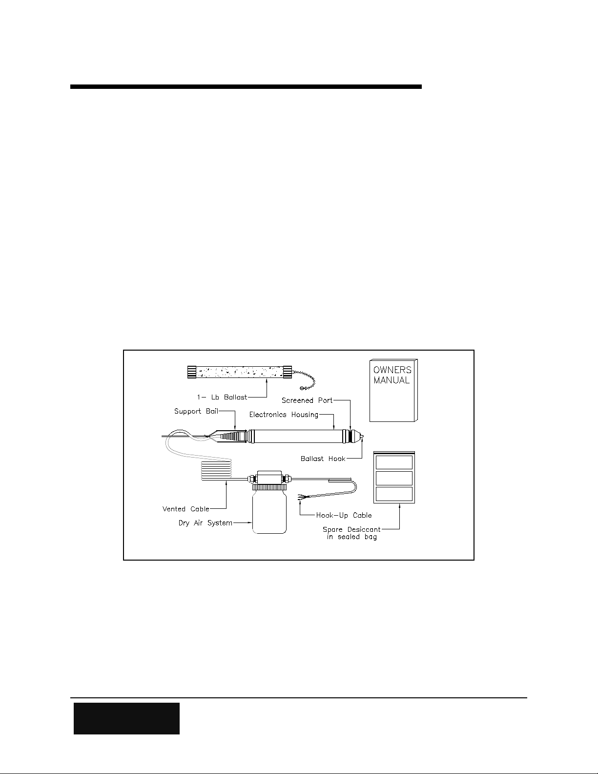
1.1 Unpacking the H-310
The following is a list of items you should have received:
Chapter 1
Unpacking the H-310
W
ATERLOG
Dry Air System
A one pound cement ballast
Three spare desiccant packs
The H-310 Owner's Manual
Stainless steel suspension cable and miscellaneous hardware (optional)
®
H-310 pressure transducer with polyethylene vented cable and H-305
Figure 1-1
Be sure that the vented cable is long enough to reach from the depth location selected to the
junction box of the dry air system. Also, be sure that the hook-up cable is long enough to reach
from the dry air system junction box to your data recorder.
H-310 Unpacking the H-310 1-1

1.2 Checking the Model Number
Before installing your new WATERLOG® H-310, check the information on the label of the sensor
enclosure. Check the model number, the range, and the output type to be sure that you have
received the instrument you ordered. The label will look similar to the following:
Model: H-310
Range: 0-15 psi
Output: SDI-12
Input: 9.6 to 16.0 volts
S/N: 12345
This example shows that the W
ATERLOG
®
H-310-15 measures pressure within the range from
zero to 15 psi. This model works with a recording device that follows the SDI-12 protocol.
The full order number tells other details about the H-310. The key to the H-310 ordering system
is in Appendix B.
1.3 Testing the System
Before placing the H-310 in your selected location, you may wish to test the system by hooking
up the H-310 with your data recorder in the shop or lab, (as explained in this manual). Testing
the WATERLOG® H-310 in the shop or lab in a bucket of water, and observing the data recorder's
readings is good. This familiarizes the user with the H-310 and the data logger in a clear, easy to
work in, environment. You are also close to the telephone if questions should arise. However,
for this test to work correctly, you must run a wire from inside the bucket that comes in
contact with the water back to the chassis ground of the data recorder. This will insure
that there is a good earth ground connection. The purpose for this ground connection is to
remove AC coupled noise from the bucket.
1-2 Unpacking the H-310 H-310

2.1 Installing the WATERLOG® H-310 and the H-305
Chapter 2
Installation
To install the W
at the desired location and connect the hook-up cable from the H-305 junction box to your data
logger.
2.1.1 Sensor Deployment
There are as many ways to deploy the H-310 as there are customers. However, as versatile as the
H-310 is, there are some site preparations and maintenance that must be considered.
1. If the sensor is to be clamped or tied down at a fixed location, the sensor must be where there
is no velocity flow. The WATERLOG® H-310 is a pressure sensor and changes in flow
correlate to changes in pressure. Thus, if the sensor is subjected to open flow, there is a good
chance your readings will be inconsistent. Key point: Use stilling wells, sand points, or
other "no flow" installation techniques. The result will be very accurate, reliable data.
2. The H-310 can be hung in well bores and float type stilling wells or conduits. If this is the
type of installation that is being done, the H-310 should be installed by suspending the sensor
not by its polyethylene vent cable, but by using a stainless steel drop cable and by using a
weighted ballast or sinker, such as the one that has been provided. The ballast will cause the
sensor to sink to the desired depth and will help the sensor to hang straight down. The
stainless cable and the miscellaneous hardware can be purchased from Design Analysis
Associates, or from a number of other sources.
ATERLOG
®
H-310 sensor and the H-305 dry air system, simply deploy the H-310
The polyethylene vent cable has an extremely large thermal coefficient of expansion. This
coupled with the fact that the polyethylene tubing will stretch with applied weight, make the use
of the stainless steel drop cable a must. Use of the stainless steel drop cable will insure long
term stability. THIS IS A MUST!!!
One end of the stainless steel tube is attached to the support bail on the sensor and the other end
is fastened to a fixed reference point at the surface. The ballast is attached to the ballast hook of
the sensor, as shown in Figure 2-1.
H-310 Installation 2-1
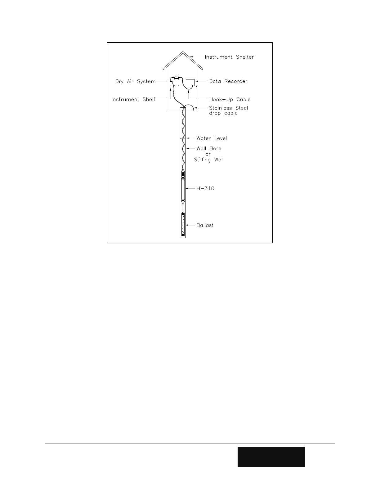
Figure 2-1
3. The H-305 dry air system should be placed in an easily accessible spot. This allows the user to
maintain the desiccant, and if needs be, the wiring inside the junction box.
The H-305 dry air system is designed to protect the sensor from moisture accumulation. The
desiccant inside the dry air system should be checked every 3 to 6 months. The desiccant bags
have a transparent strip which allows the condition of the desiccant to be visually checked. Dry
desiccant is dark blue and saturated desiccant will have turned pink. The desiccant packs can be
reused by drying them in an oven at 125F to 150F for 4 to 8 hours or until the desiccant returns
to a dark blue color.
2-2 Installation H-310
 Loading...