


INSTRUCTION MANUAL
IM103
5" and Larger
Submersible Pump
INSTALLATION AND OPERATION INSTRUCTIONS

TABLE OF CONTENTS
SUBJECT PAGE
Safety Instructions .................................................................................................................................................................... 3
1.0 Preparing for Installation .................................................................................................................................................... 4
2.0 Mechanical Installation.......................................................................................................................................................4
3.0 Electrical Instructions ........................................................................................................................................................ 5
4.0 Operate Pump .................................................................................................................................................................... 7
5.0 Literature and IOM ............................................................................................................................................................ 7
6.0 Accessories .........................................................................................................................................................................7
Single Phase Wiring ..................................................................................................................................................................8
Three Phase Wiring ..................................................................................................................................................................9
Technical Data ........................................................................................................................................................................10
Three Phase, 4" Motor - Electrical Data ..................................................................................................................................12
Generation II - 3-Wire, Single Phase, 4" Motors - Electrical Data ............................................................................................12
6" Single Phase Motors and Required Control Boxes ..............................................................................................................13
6-10" Three Phase Motors ...................................................................................................................................................... 13
6" Single Phase Motors ........................................................................................................................................................... 14
6-10" Three Phase Motors ...................................................................................................................................................... 14
Three Phase Power Unbalance ................................................................................................................................................15
Troubleshooting .....................................................................................................................................................................16
Limited Warranty ...................................................................................................................................................................17
Owner’s Information
Owner’s Information
Pump Model Number:
Pump Serial Number:
Motor Model Number:
Motor Serial Number:
Dealer:
Dealer Telephone:
Purchase Date:
Installation Date:
Dole® is a Registered Trademark of Eaton Corporation.
Cla-Val™ is a Trademark of Griswold Ind.
2
WARNING
WARNING
WARNING
SAFETY INSTRUCTIONS
WARNING
CAUTION
WARNING
WARNING
WARNING
WARNING
WARNING
WARNING
DANGER
WARNING
CAUTION
DANGER
TO AVOID SERIOUS OR FATAL PERSONAL INJURY OR MAJOR PROPERTY DAMAGE, READ AND FOLLOW ALL
SAFETY INSTRUCTIONS IN MANUAL AND ON PUMP.
THIS MANUAL IS INTENDED TO ASSIST IN THE INSTALLATION AND OPERATION OF THIS UNIT AND MUST BE
KEPT WITH THE PUMP.
This is a SAFETY ALERT SYMBOL. When you see this symbol on the pump or in the manual, look for one of
the following signal words and be alert to the potential for personal injury or property damage.
DANGER
WARNING
CAUTION
Warns of hazards that WILL cause serious personal injury, death or major property damage.
Warns of hazards that CAN cause serious personal injury, death or major property damage.
Warns of hazards that CAN cause personal injury or property damage.
NOTICE: INDICATES SPECIAL INSTRUCTIONS WHICH ARE VERY IMPORTANT AND MUST BE FOLLOWED.
THOROUGHLY REVIEW ALL INSTRUCTIONS AND WARNINGS PRIOR TO PERFORMING ANY WORK ON THIS PUMP.
MAINTAIN ALL SAFETY DECALS.
Important notice: Read safety instructions before proceeding with any wiring
All electrical work must be performed by a qualified technician. Always follow the National Electrical Code
(NEC), or the Canadian Electrical Code, as well as all local, state and provincial codes. Code questions should be
directed to your local electrical inspector. Failure to follow electrical codes and OSHA safety standards may result in personal
injury or equipment damage. Failure to follow manufacturer’s installation instructions may result in electrical shock, fire hazard,
personal injury or death, damaged equipment, provide unsatisfactory performance, and may void manufacturer’s warranty.
Standard units are designed to pump potable water from wells and storage tanks. They are not designed for use
in swimming pools, open bodies of water, hazardous liquids, or where flammable gases exist. Well must be vented
per local codes.
Only pumps specifically Listed for Class 1, Division 1 are allowable in hazardous liquids and where flammable gases may exist.
See specific pump catalog bulletins or pump nameplate for all agency Listings.
Disconnect and lockout electrical power before installing or servicing any electrical equipment. Many pumps are
equipped with automatic thermal overload protection which may allow an overheated pump to restart
unexpectedly.
Do not lift, carry or hang pump by the electrical cables. Damage to the Electrical Cables can cause shock,
burns or death.
Use only stranded copper wire to pump/motor and ground. The ground wire must be at least as large as the power
supply wires. Wires should be color coded for ease of maintenance and troubleshooting.
Install wire and ground according to the National Electrical Code (NEC), or the Canadian Electrical Code, as well
as all local, state and provincial codes.
Install an all leg disconnect switch where required by code.
The electrical supply voltage and phase must match all equipment requirements. Incorrect voltage or phase can
cause fire, motor and control damage, and voids the warranty.
All three phase (3Ø) controls for submersible pumps must provide Class 10, quick-trip, overload
protection.
All splices must be waterproof. If using splice kits follow manufacturer’s instructions.
Select the correct type and NEMA grade junction box for the application and location. The junction box must
insure dry, safe wiring connections.
Failure to permanently ground the pump, motor and controls before connecting to power can cause shock, burns
or death.
Insure proper motor cooling, see Table 3, minimum flow rates chart in Technical Section.
This pump has been evaluated for use with Water Only.
Never over pressurize a storage tank to a pressure higher than the tank's maximum pressure rating. This will
damage the tank, voids the warranty and may create a serious hazard.
3
1.0 PREPARING FOR INSTALLATION
1.0 PREPARING FOR INSTALLATION
The well should be developed (cleaned) and disinfected
before the pump is installed.
Write the pump model number, pump serial number and
motor serial number in the space provided in this Installation
and Operation Manual (IOM). Leave the completed IOM
attached to the tank or control box in a dry area or give it to
the owner. Attach your business card.
Verify that motor voltage, control voltage, coil voltage
(3 phase starters) and power supply voltage match. Electrical
installation must be performed by qualified personnel.
Inspect all components for shipping damage and insure that
you have all the components that are required: Pump Water
End, Motor, 1Ø Motor Control Box or 3Ø Starter with
Overloads, Pressure Tank, Pressure Switch, Copper Wire,
Pressure Relief Valve (if required), Torque Arrestor (if
required), Pipe and Fittings.
2.0 MECHANICAL ASSEMBLY – Pump and Piping
2.0 MECHANICAL ASSEMBLY – Pump and Piping
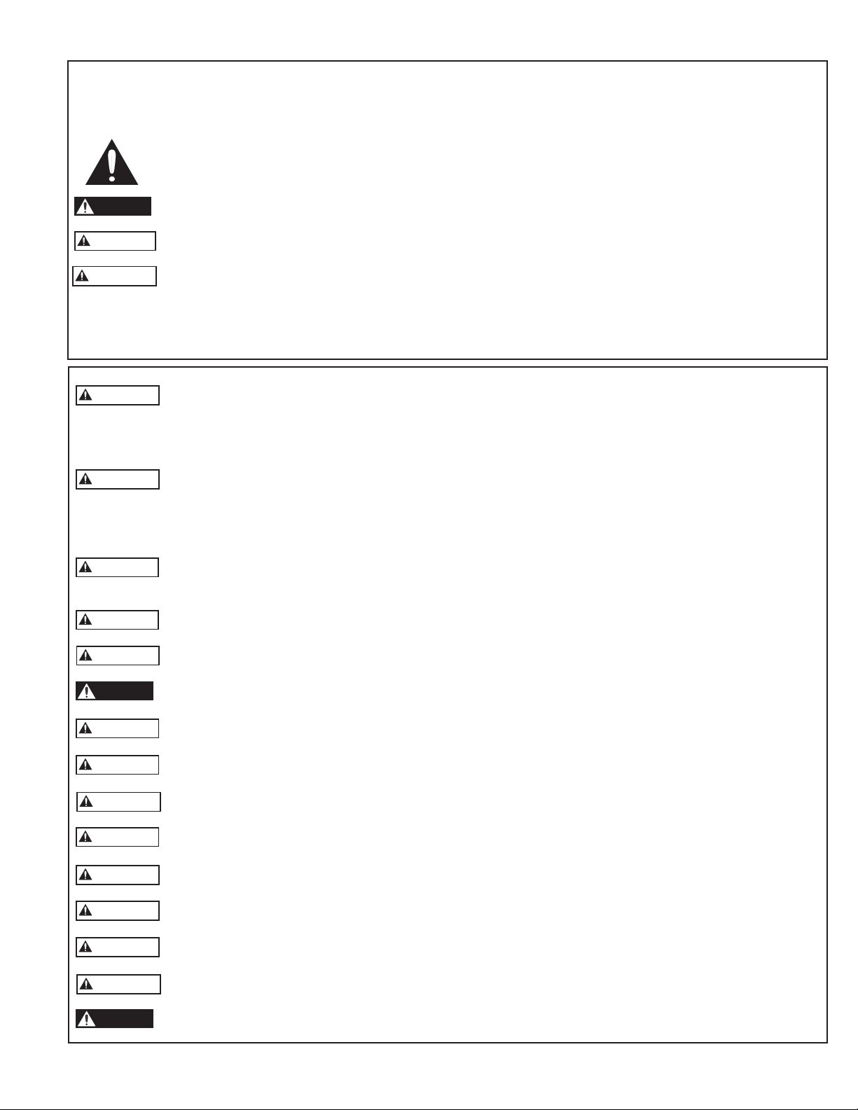
2.1 Typical Systems
Pump in “Can”
Figure 3
Figure 1
Pump with Flow Sleeve in Tank
Figure 4
Pump with Flow Sleeve in Large Diameter Well
Figure 5
Horizontal Pump in “Can”
Figure 6
Figure 2
4

2.2 Assemble Pump End to Motor
Under no circumstance should the pump be run dry. Doing
so may damage internal parts. We suggest you check the
rotation on a three phase motor before assembling it to the
water end (pump). All 4" and 6" single phase motors should
rotate counterclockwise when viewed from the shaft end.
Rotation on three phase motors should match pump specifications. Due to the high-starting torque the motor should
be secured in such a way as not to damage the motor but to
hold the motor from spinning.
Lower the pump into the well. Set the pump at least 10' off
the bottom but above the screens. Protect the wires from
chafing on the well casing. Install a pitless adapter or similar
device at the wellhead. Consult the fitting manufacturer or
pitless supplier for specific installation instructions.
Using waterproof electrical tape, or wire ties, fasten the
wires to the drop pipe at 10' intervals. Make sure that the
tape does not loosen as it will block the pump suction if it
falls down the well.
Remove the cable guard from the pump (water end). Install
the motor shaft sand slinger if included with the water end in
the motor mounting hardware package. Attach the water end
to the motor. Align the wires in the cable guard and reinstall
it to the water end.
2.3 Install Check Valve(s)
Discharge heads are threaded with NPT pipe threads. All
models, without built-in check valves, require a spring
loaded check valve within 25' (7.5m) of the pump discharge
and below the drawdown level of the water supply. Motor
manufacturers recommend additional check valves every 200'
to 250' (70m) in the vertical discharge line. Check valves are
used to hold pressure in the system and to prevent backspin,
water hammer and upthrust.
Backspin is allowing water to flow back through the pump to
drain the system. It causes the impellers and motor rotor to
rotate in a reverse direction. This can cause premature thrust
bearing wear and if the motor starts during backspin the
shaft can be twisted or broken.
Water Hammer occurs when the lowest check valve is more
than 30' above the standing water level or the lower check
valve leaks and the check valve above holds. This creates a
partial vacuum (void) in the discharge piping. On the next
start, water moving at a very high velocity fills the void and
strikes the closed check valve and the stationary water in the
pipe above it, causing a hydraulic shock. This shock (water
hammer) can split pipes, break joints, and damage the pump
and motor. Water hammer is an easily detected noise. When
discovered the pump should be immediately shut down and
the installer contacted to resolve the problem.
2.5 Pressure Relief Valve
Pressure relief valves are mandatory (required) on any system
that is capable of producing over 100 psi or 230' TDH. In
an area where a water leak or blow-off may damage property
connect a drain line to the pressure relief valve. Run it to a
suitable drain or an area where the water will not damage
property.
2.6 Pressure Tank and Pressure Switch
(when used)
The pressure switch should be located at the tank cross tee
on a single tank and as close to the center as possible on
multiple tank installations. Multiple tank installations should
have a manifold pipe 1½ to 2 times the size of the supply
pipe from the pump. This is to reduce the friction head loss
or pressure differential in the manifold. Excessive losses
could cause switch chatter. There should be no filters, or
high loss fittings between the switch and the tank(s). Wide
open gate valves are allowed between the tank and switch.
2.7 Adjusting Tank Pre-Charge (when used)
Insure that the tank is empty of water. Use a high quality
pressure gauge to check the tank pre-charge pressure. The
pressure should be 2 psi below the pump cut-in (turn on)
pressure. As an example, a 30-50 psi system would use a
tank pre-charge of 28 psi.
Select an area where the temperature is above 34° F in which
to install the tank, pressure switch, and pressure relief valve.
The tank should be located in an area where a leak will not
damage property.
3.0 ELECTRICAL INSTRUCTIONS
3.0 ELECTRICAL INSTRUCTIONS
Upthrust is an upward movement of the impellers and motor
shaft. It is caused by starting the pump at zero head due to
no check valve or a leaking check valve; or very low system
head due to a high static water level. Repeated upthrust can
cause premature failure of either or both the pump and the
motor. See 4.2
2.4 Installing Pump in Well
If you are using a torque arrestor, install it per the manufacturer’s installation instructions. On top feeding wells or large
diameter wells where water velocity will not cool the motor properly install a flow sleeve over the pump. See Table 3
– Required Cooling Flow.
Connect the discharge pipe to the pump discharge head.
Submersible pumps are capable of very high discharge pressures, consult with your pipe supplier to determine the best
pipe material and schedule for each installation.
3.1 General
Note: Do not power the unit or run the pump until all
electrical and plumbing connections are completed and the
pump is filled with water.
Always follow the National Electric Code (N.E.C.) in the
U.S., or the Canadian Electrical Code in Canada, as well as
all state, provincial, or local codes.
All electrical work must be performed by qualified
personnel. Some local laws require installation by only
“licensed installers”.
We suggest using only copper wire. Size wire from the charts
found in our ITT MAID, Motor Application & Installation
Manual, or an N.E.C.( National Electric Code) manual. If
discrepancies exist the N.E.C. in the U.S., and in Canada the
Canadian Electrical Code prevails.
5

3.2 Splice Drop Cable to Motor Leads
When the drop cable must be spliced or connected to the
motor leads it is necessary that the splice be watertight. The
splice can be done with heat shrink kits, compression fittings,
or waterproof tape. Match motor leads and drop cable by
color codes or identify drop cable wires to insure a proper
connection at the control box.
A. Heat Shrink Splice Instructions
To use a typical heat shrink kit: strip ½" from the motor
wires and drop cable wires, it is best to stagger the splices.
Place the heat shrink tubes on the wires. Place the crimps
on the wires and crimp the ends. Slide the heat shrink
tubes over the crimps and heat from the center outward.
The sealant and adhesive will ooze out the ends when the
tube shrinks. The tube, crimps, sealant, and adhesive
create a very strong, watertight seal. Overheating may
burn the heat shrink tubes.
B. Taped Splice Instructions
1) Strip individual conductor of insulation only as far as
necessary to provide room for a stake type connector.
Tubular connectors of the staked type are preferred. If
connector O.D. is not as large as cable insulation,
build-up with rubber electrical tape.
2) Tape individual joints with rubber electrical tape, using
two layers; the first extending two inches beyond each
end of the conductor insulation end, the second layer two
inches beyond the ends of the first layer. Wrap tightly,
eliminating air spaces as much as possible.
3) Tape over the rubber electrical tape with #33 Scotch
electrical tape, or equivalent, using two layers as in step
“B” and making each layer overlap the end of the
preceding layer by at least two inches.
C. Compression Splice Kits
Consult instructions supplied with compression splice kits
or consult your local supplier.
3.3 Mounting the Motor Control Box
Single phase 3-wire control boxes are suitable for vertical
mounting in indoor or outdoor locations. They will operate
at temperatures between 14ºF ( -10º C) and 122º F (50º C).
Select a shaded, dry place to mount the box. Insure that there
is enough clearance for the cover to be removed.
3.6 Make Connection to Single Phase (1Ø)
Control Box or Three Phase (3Ø) Starter
DANGER
Do not power the unit or run the pump until all electrical
and plumbing connections are completed. Exception – to
verify 3 phase motor rotation, it is acceptable to power the
motor before it is attached to the water end to verify correct rotation. After checking rotation lock-out disconnect or
circuit breaker in OFF position!
Verify that the disconnect or breaker is OFF before making any connections to the power supply. Always follow the
National Electric Code (N.E.C.) in the U.S., or the Canadian
Electrical Code in Canada, as well as all state, provincial, or
local codes.
A. Single Phase (1Ø) Three-Wire Control Box Wiring
CAUTION
Connect the color coded motor leads to the motor
control box terminals –
Y (yellow), R (red), and B (black); and the Green or bare
wire to the green ground screw.
Connect wires between the Load terminals on the pressure switch and control box terminals L1 and L2. Run a
ground wire between the switch ground and the control
box ground. See Fig. 7 or 8
B. Three Phase (3Ø) Starter Wiring
CAUTION
Connect the motor leads to T1, T2, and T3 on the 3
phase starter. Connect the ground wire to the ground
screw in the starter box. Follow starter manufacturers
instructions for connecting pressure switch (where used)
to starter. See Fig. 9 or 10
3.7 Make Power Supply Connection
CAUTION
Provide a separate fused or circuit breaker protected branch
circuit for the pump. Install a main disconnect switch in full
view and easily accessible from the pressure switch and tank
location.
3.4 Verify Voltage
Insure that motor nameplate voltage and power supply
voltage are the same. Three-phase starter coils are very
voltage sensitive, always verify actual supply voltage with
a voltmeter. High or low voltage will damage motors and
controls and is not covered under warranty.
3.5 Turn Supply Power Off
Use a disconnect switch where required by code. Turn the
circuit breaker OFF and lock-out the disconnect switch in
the OFF position to prevent accidentally starting the pump
before you are ready.
6
Single phase:
With pressure switch – make the connection from the pressure switch Line terminals to the disconnect switch (where
used) and then to the circuit breaker panel.
Without pressure switch – make the connection from the
control box L1 and L2 terminals to the disconnect switch
(where used) and then to the circuit breaker panel.
Three phase - make the connections between L1, L2, L3, and
ground on the starter to the disconnect switch and then to
the circuit breaker panel.

Three phase submersible motors require Class 10 Quick-Trip
overload protection. Use Furnas Class 14 NEMA starters
with ESP100 adjustable Class 10 overloads. You can also
use Furnas Class 16 starters with ambient compensated “K”
heaters (overloads) which you install in the starter. “K” heaters must be purchased separately. Consult the ITT MAID or
F.E. AIM manual for other acceptable overload protection
devices.
Note: when replacing a line shaft turbine or other above
ground pump with a submersible you must change the Class
20 overloads in the starter to Class 10 quick-trip’s for proper
motor overload protection. Use of Class 20 overloads voids
the submersible motor warranty.
Three phase installations must be checked for motor rotation
and phase unbalance. To reverse motor rotation switch (reverse) any two power leads. See the instructions for checking three phase unbalance in the Technical Section of this
manual. Failure to check and correct three phase unbalance
can cause premature motor failure and nuisance overload
tripping.
4.0 OPERATE PUMP
4.0 OPERATE PUMP
Check amps and insure they are within nameplate amp range
from motor data sheet or motor nameplate. Amps should be
between Rated Input and Service Factor Amps. High amps
may be caused by low or high voltage. Enter the amp readings in this manual along with the pump and motor model
numbers and serial numbers. On all three phase systems a
three phase unbalance test must be performed to insure a
balanced power supply. Leave a copy of the 3Ø unbalance
worksheet with this IOM at the job site for future reference.
On pressure tank/switch systems only – close the valve when
the water clears and allow the pressure to build. If properly
adjusted the switch should turn the pump off at the preset
pressure. Open a few outlets and allow the pump to run
through a few cycles. Check switch operation and verify that
pressure settings are correct. Check all fittings for leaks.
On manual systems, turn the pump off.
5.0 PAPERWORK AND IOM
5.0 PAPERWORK AND IOM
Please give this IOM and your business card to the owner.
A sticker with your name and phone number on the tank or
control box is a great sales tool for future business!
4.1 Throttling Discharge on Start-Up
If the pump will be started or operated with an “open”
discharge you must throttle the discharge before start-up.
Install a ball, globe, or Cla-valve® in the discharge line. Open
the valve to approximately 1⁄3 open on system start-up. This
will prevent upthrust damage to the pump and motor
bearings. You can open the valve when you get a good steady
stream of water. Do not exceed the maximum operating
range in gpm shown on the pump curve. If you do not know
the maximum gpm for the pump, call the distributor who
sold you the pump. Starting or running a pump with little or
no head is a major cause of premature failure.
4.2 Throttling a High Static Level Well to
Prevent Upthrust
A high static water level well may allow a pump to operate
off the right side of the curve or outside the “Recommended
Range” shown on the pump curve. We recommend using a
“Dole®” flow restrictor or throttling the discharge with a ball
valve to prevent upthrust damage to the pump and motor.
The maximum flow must be within the pumps recommended
operating range. If you use a ball valve, set it and remove the
handle, tape the handle to the pipe. Tag the valve with a note
saying, “Do not open this valve or pump may be damaged”.
You can set the valve by installing a pressure gauge between
the well and the valve and throttling the flow/head to a value
within the recommended range. You can also throttle by determining the actual flow rate, see “Determining Flow Rates”
in your catalog Technical Section.
Congratulations on completing a professional installation of
a submersible pump.
6.0 ACCESSORIES
6.0 ACCESSORIES
Pressure Tanks
Tanks should be sized to allow pumps over two (2) hp to run
at least 2 minutes. If the pump averages 80 GPM it requires
tanks to provide a 160 gallon “drawdown”. See your Water
Products catalog for pressure tank data.
Low Water Protection
A low yield well should have low water protection added
to the system. Contact your distributor for information on
SymCom low water protection devices.
Electrical Panels
Customer Service will quote custom pump control panels.
Please send written panel specifications to your authorized
distributor. They will forward it to the Customer Service
Group that supports their product line. Written specifications
should include pump HP, Voltage, Phase, desired NEMA enclosure type, sequence of operation, special options needed,
and a brief statement describing any special logic for alarms,
timers, or duplexing features. The name and number of a
contact person to answer questions is also appreciated and
will speed your quote.
4.3 Start the Pump
Partially open a valve (boiler drain or faucet) in the system
and turn the breaker to the ON position. Allow the pump
to run until the water is clear. On three phase systems verify
rotation, correct rotation will yield the highest flow and
pressure.
7
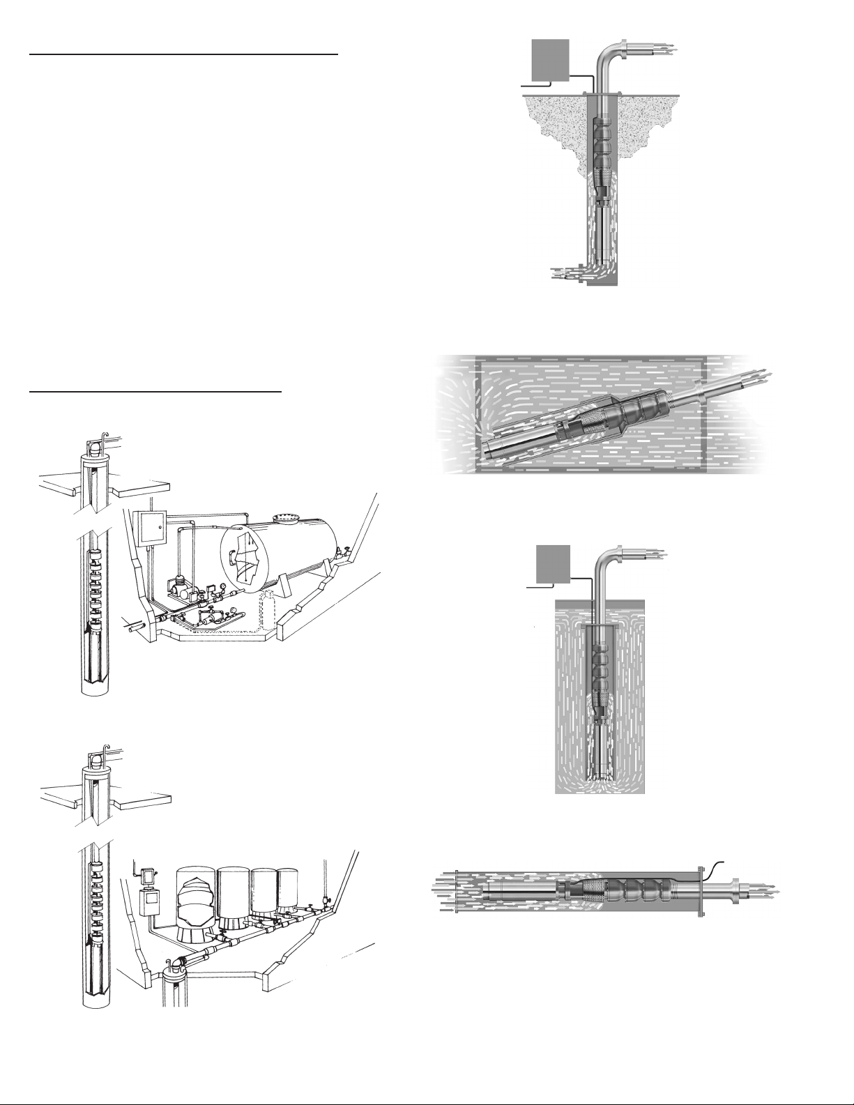
Single Phase Wiring — Cableado monofásico — Montage monophasé
Single Phase Wiring — Cableado monofásico — Montage monophasé
Incoming Supply from Fuse Box or Circuit Breaker (1)
1. Suministro de entrada de la caja de fusibles o del cortacircuitos
L1 L2
R Y Blk
Red
(8)
(9) (10)
L1 L2
Disconnect
Switch (2)
(4)
L1 L2
Black
Yellow
(3)
Three Wire
Control Box
Three Wire – Direct Connected to Pressure Switch
Trifilar – conectado directamente al interruptor
Line
Load
Load
Line
NOTE: SymCom PumpSaver (6)
(7)
por caída de presión
Moteur à trois fils – relié au prossostat
Figure (Figura) 7
Incoming Supply from Fuse Box or Circuit Breaker
Pressure
Switch
(5)
(1)
2. Interruptor de desconexión
3. Línea
4. Carga
5. Interruptor por caída de presión
6. NOTA: PumpSaver
7. Caja de control trifilar
8. Rojo
9. Amarillo
10. Negro
11. Contactador magnético
1. Courant d’entrée provenant de la boîte à fusibles ou du disjoncteur
2. Sectionneur
3. Ligne
4. Charge
5. Pressostat
6. Protection PumpSaver
7. Boîte de commande à trois fils
8. Rouge
9. Jaune
L1 L2
R Y Blk
Red
(8)
(9)
T1 T2
L1 L2
Black
Yellow
(10)
Disconnect
Switch (2)
(3)
Magnetic Contactor (11)
Three Wire
Control Box (7)
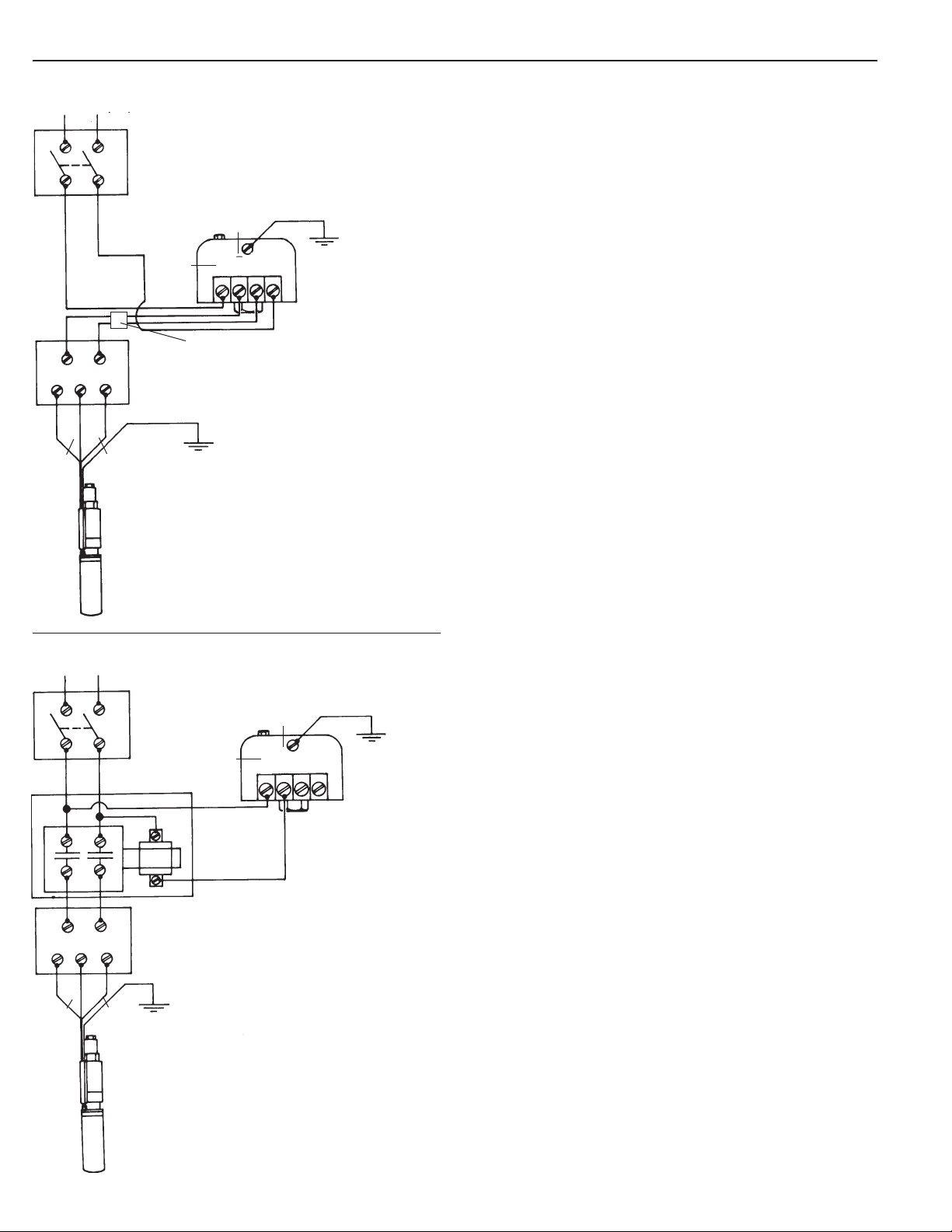
Three Wire – Connected through Magnetic Contactor
Trifilar – conectado a través del contactador magnético
Moteur à trois fils – relié par
contacteur magnétique
Line
(4)
Load
Load
Line
Pressure
Switch (5)
10. Noir
11. Contacteur magnétique
Figure (Figura) 8
8
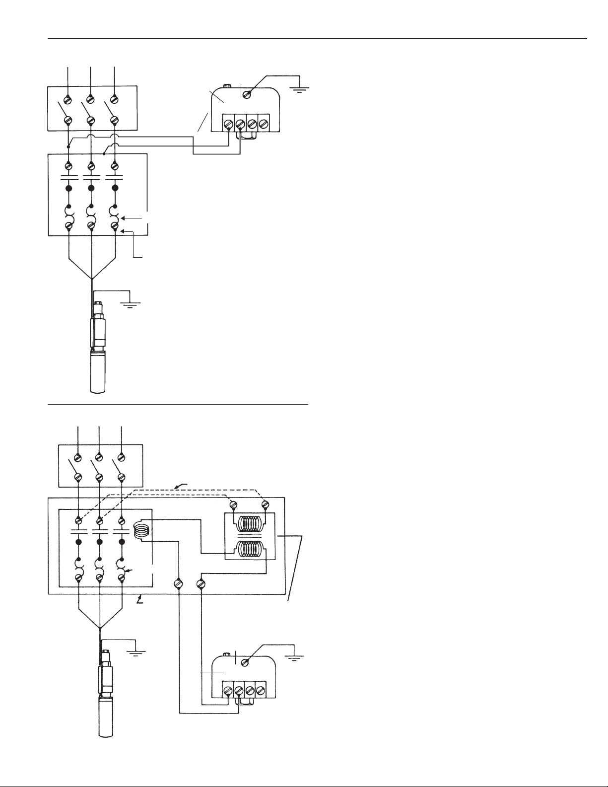
Three Phase Wiring — Cableado trifásico — Montage triphasé
Three Phase Wiring — Cableado trifásico — Montage triphasé
Incoming Supply from Fuse Box or Circuit Breaker (1)
1. Suministro de entrada de la caja de fusibles o del cortacircuitos
L1 L2 L3
3
T1 T2 T3
Incoming Supply from Fuse Box or Circuit Breaker (1)
(4)
(3)
Disconnect
Switch (2)
Pressure Switch
Heaters (6)
Ambient Compensated
Magnetic Starter with
Quick-Trip Heaters
Three Phase Starter and Pressure Switch
Tres conexiones de fase
Pressostat et démarreur triphasé
(7)
Line
Load
(5)
Load
Line
Figure (Figura) 9
2. Interruptor de desconexión
3. Línea
4. Carga
5. Interruptor por caída de presión
6. Calentadores
7. Arrancador magnético con compensación ambiental con calentadores de disparo rápido
8. Interruptor por caída de presión u otros interruptores pilotos
9. Tierra
10. Puesta a tierra opcional del motor
11. Conexión de campo
12. Transformador de control (Las derivaciones deben coincidir con la
tensión de suministro)
1. Courant d‘entrée provenant de la boîte à fusibles ou du disjoncteur
2. Sectionneur
3. Ligne
4. Charge
5. Pressostat
6. Dispositifs de protection contre la surcharge (DPS)
L1 L2
T1 T2 T3
Disconnect
Switch (2)
Field Connected (11)
L1 L2
L3
2 3
Ambient
Compensated
Magnetic Starter
with Quick-Trip
Heaters (7)
Optional Motor
Grounding (10)
Three Phase Starter with Control Voltage Transformer
Arrancador trifásico con transformador de tensión de control
Démarreur triphasé avec transformateur de tension de commande
(9) GND
(3)
Control Transformer
(Shunts must be
matched to the Supply Voltage) (12)
(4)
Line
Load
Load
Line
Pressure
Switch
or other
Pilot
Switches (8)
Figure (Figura) 10
7. Démarreur magnétique compensé (température ambiante) avec
DPS à déclenchement rapide
8. Pressostat ou autre contacteur de commande
9. Terre
10. Mise à la terre optionnelle pour le moteur
11. Connexion sur place
12. Transformateur de commande (les circuits dérivés [
convenir à la tension d’alimentation)
shunts
] doivent
9
Technical Data
CAUTION
Technical Data
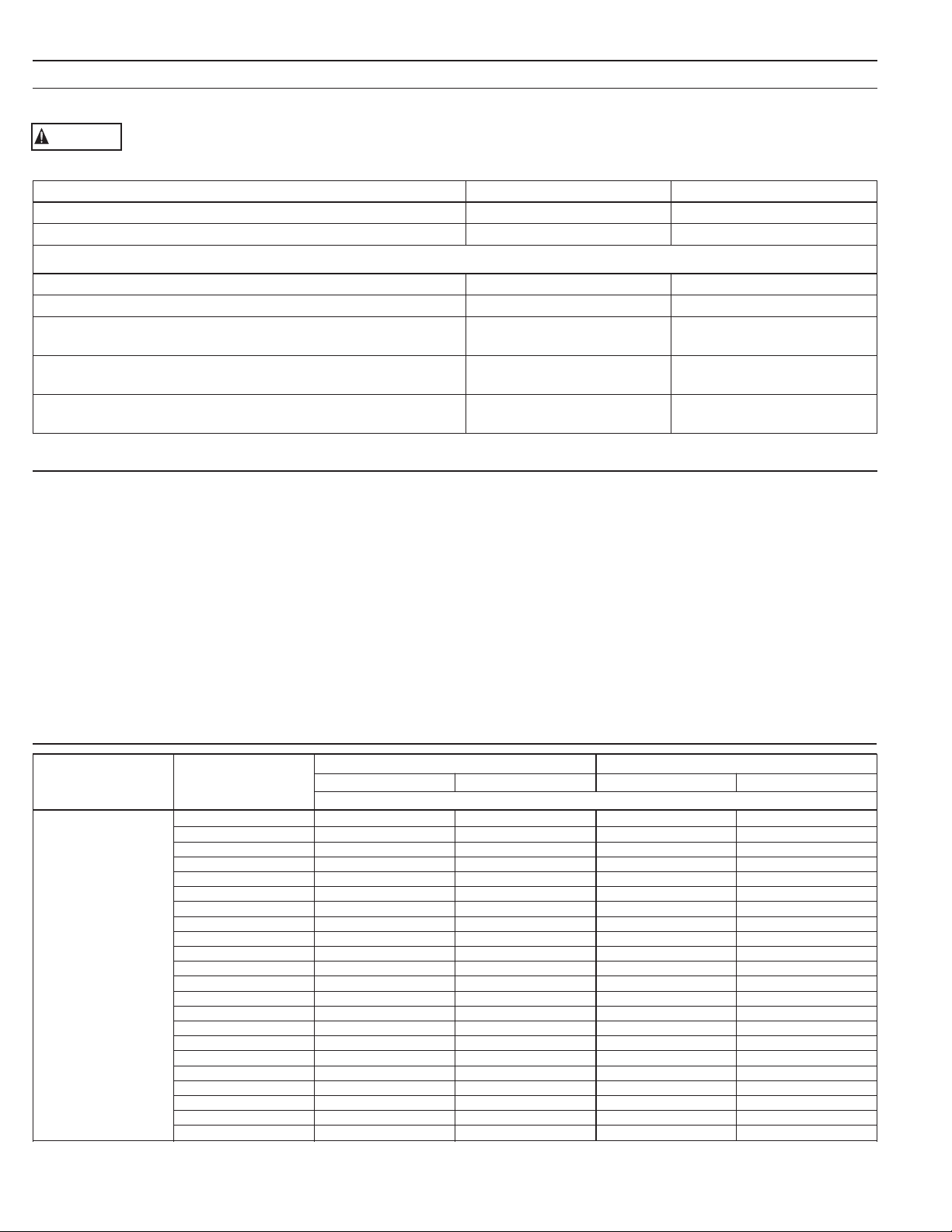
MOTOR INSULATION RESISTANCE READINGS
Normal Ohm/Megohm readings, ALL motors, between all leads and ground
To perform insulation resistance test, open breaker and disconnect all leads from QD control box or
pressure switch. Connect one ohmmeter lead to any motor lead and one to metal drop pipe or
a good ground. R x 100K Scale
Condition of Motor and Leads OHM Value Megohm Value
New motor, without power cable 20,000,000 (or more) 20.0
Used motor, which can be reinstalled in well 10,000,000 (or more) 10.0
Motor in well – Readings are power cable plus motor
New motor 2,000,000 (or more) 2.0
Motor in reasonably good condition 500,000 to 2,000,000 0.5 – 2.0
Motor which may be damaged or have damaged power cable
Do not pull motor for these reasons
Motor definitely damaged or with damaged power cable
Pull motor and repair
Failed motor or power cable
Pull motor and repair
Generator Sizing
Generator Sizing
Note: Always consult the generator
manufacturer when questions arise.
These sizing charts are recommendations based on motor
service factor loading for typical continuous duty generators. If
you need to call the generator manufacturer, be prepared to tell
them the motor KVA code, the service factor amperage, locked
rotor amperage, phase, hertz, motor type, etc.
You must know which type generator you have before using the
charts as the required generator size varies by type. Internally
regulated generators are also called self-excited. Externally
regulated generators are the most common. In addition to the
Kw/KVA rating, the generator frequency (Hertz, typically
Less than 10,000 0 – 0.01
60 HZ in USA) is very important when operating pumping
equipment because frequency variations affect pump output in
direct relation to the pump Affinity Laws. Operating under 60
hertz will reduce flow and head while operating over 60 hertz
will increase flow, head, HP and amp draw and could overload
the motor.
The generator should always be started before the pump/
motor is started and always stop the pump/motor before
shutting down the generator. Operating generators at higher
elevations or using natural gas as fuel can affect performance,
consult the generator manufacturer for their recommendations
in these instances.
20,000 to 500,000 0.02 – 0.5
10,000 to 20,000 0.01 – 0.02
Generator Recommendations
Generator Recommendations
Externally Regulated Internally Regulated
Motor HP KW KVA KW KVA
Minimum Generator Rating
.5 2 2.5 1.5 1.9
.75 3 3.8 2 2.5
1 4 5 2.5 3.2
1.5 5 6.3 3 3.8
2 7.5 9.4 4 5
3 10 12.5 5 6.3
5 15 18.8 7.5 9.4
7.5 20 25 10 12.5
40 100 125 50 62.5
50 150 188 60 75
60 175 220 75 94
75 250 313 100 125
100 300 375 150 188
125 375 469 175 219
150 450 563 200 250
175 525 656 250 313
200 600 750 275 344
10 30 37.5 15 18.8
3-Wire
15 40 50 20 25
1Ø
20 60 75 25 31
and
25 75 94 30 37.5
3Ø
30 100 125 40 50
Motors
10

Technical Data (Continued)
Technical Data
Transformer Capacity Required for Submersible
Motors – Single or Three Phase
Distribution transformers must be adequately sized to satisfy
the KVA requirements of the submersible motor. When
transformers are too small to supply the load, there is a
reduction in voltage to the motor.
Table 1 references the motor horsepower rating, single
phase and three phase, total effective KVA required, and the
smallest transformer required for open or closed three phase
systems. Open systems require larger transformers since only
two transformers are used.
Other loads would add directly to the KVA sizing requirements of the transformer bank.
Table 1 – Transformer Capacity
Smallest KVA Rating –
Each Transformers
Motor HP Open WYE Closed
Total Effective or DELTA WYE or DELTA
KVA Required 2 Transformers 3 Transformers
1½ 3 2 1
2 4 2 1.5
3 5 3 2
5 7.5 5 3
7½ 10 7.5 5
10 15 10 5
15 20 15 7.5
20 25 15 10
25 30 20 10
30 40 25 15
40 50 30 20
50 60 35 20
60 75 40 25
75 90 50 30
100 120 65 40
125 150 85 50
150 175 100 60
175 200 115 70
200 230 130 75
NOTE: Transformers shown are standard nominal KVA ratings. If power company experience
and practice allows transformer loading higher than nominal rating under the specific operating conditions and maintains correct voltage and balance, such higher loading values may be
used for transformer(s) to meet total effective KVA required.
Mounting Position
Motors are suitable for operation in mounting positions
from vertical shaft up to horizontal. If 4 inch motors through
2 HP are started more than 10 times per day, it is recommended the shaft be tilted up at 15° from horizontal to
minimize coast-down wear of the upthrust washer.
Frequency of Starts
The average number of starts per day over a period of
months or years influences the life of a submersible pumping
system. Excessive cycling affects the life of control components such as pressure switches, starters, relays and capacitors, plus splines and bearings. Rapid cycling can also cause
motor overheating and winding failures.
The pump size, tank size and other controls should be selected to keep the starts per day as low as practical for longest
life, based upon the maximum number of starts per 24 hour
day, as shown in Table 2.
Motors over 2 HP should be allowed to run a minimum of
2 minutes to dissipate heat build up from starting current.
Table 2 – Number of Starts
Maximum Starts per 24 hour day
Motor Rating
½ HP through 5 HP 100 300
7½ HP through 30 HP 50 100
40 HP and over — 100
Single Phase Three Phase
Motor Cooling, Temperature and Time Ratings
All 4 inch CentriPro motors may be operated continuously
in water up to 86º F. Optimum service life will be attained
by maintaining a minimum flow rate past the motor of .25
feet per second. Use a Flow Sleeve if velocity is below the
.25'/sec, if the well is top feeding or when the pump is used
in a large body of water or large tank.
Six (6) inch canned design motors from 5 – 40 HP will
operate in water up to 95º F (35º C), without any de-rating
of horsepower, with a minimum flow rate of .5 ft./sec. past
the motor. 6" – 50 HP and all 8" – 10" motors can operate in
77º F (25º C) water with .5'/sec velocity past the motor.
Table 3 – Minimum Flow Rates For Proper Motor Cooling
Diameter
4 1.2 – –
5 7 – –
6 13 7 –
7 20 23 –
8 30 41 9
10 50 85 53
12 80 139 107
14 110 198 170
16 150 276 313
Multiply gpm by .2271 for m3/Hr.
Multiply gpm by 3.785 for l/min.
3.75" Diameter CP = 5.5" Dia. CP = 7.52" Dia.
Well or
4" CP or FE Motor 6" CP Motor 8" CP Motor
Sleeve
(inches)
.25'/sec .5'/sec. .5'/sec.
GPM Required
11
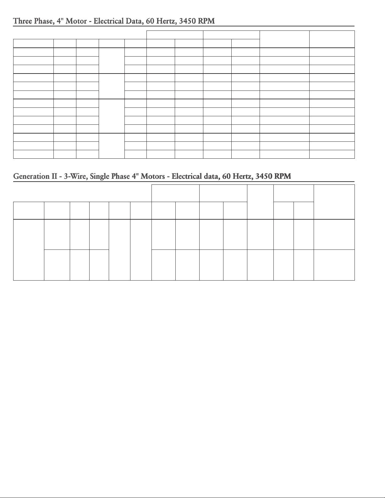
Three Phase, 4" Motor - Electrical Data, 60 Hertz, 3450 RPM
Full Load Service Factor
CentriPro # HP kW Volts SF Amps Watts Amps Watts
M30430 3 2.2
M50430 5 3.7 1.15 18.3 4850 20.2 5515 113 0.4-0.8
200
1.15 10.9 2890 12.0 3290 71 0.9-1.3
Locked Rotor
Amps
Line - Line
Resistance
M75430 7.5 5.5 1.15 27.0 7600 30.0 8800 165 0.5-0.6
M30432 3 2.2
M50432 5 3.7 1.15 15.7 4925 17.5 5650 93 .85-1.25
230
1.15 9.2 2880 10.1 3280 58.9 1.3-1.7
M75432 7.5 5.5 1.15 24 7480 26.4 8570 140 .55-.85
M30434 3 2.2
M50434 5 3.7 1.15 7.6 4810 8.5 5530 48 3.58-4.00
M75434 7.5 5.5 1.15 12.2 7400 13.5 8560 87 1.9-2.3
460
1.15 4.8 2920 5.3 3320 30 5.9-6.5
M100434 10 7.5 1.15 15.6 9600 17.2 11000 110 1.8-2.2
M30437 3 2.2
M50437 5 3.7 1.15 7.0 5080 7.6 5750 55 3.6-4.2
575
1.15 3.7 2850 4.1 3240 21.1 9.4-9.7
M75437 7.5 5.5 1.15 9.1 7260 10.0 8310 55 3.6-4.2
Generation II - 3-Wire, Single Phase 4" Motors - Electrical data, 60 Hertz, 3450 RPM
Full Load Service Factor
Type
3-Wire
with CSCR
(CR) or
Magnetic
Contactor
(MC)
Control
Box
¹ A CSCR control box with a CR suffix can be replaced by a Magnetic Contactor model ending in MC.
Order
No.
M30412 3 2.2
M50412 5 3.7
HP kW Volts SF Amps Watts Amps Watts
230 1.15
Y – 14.3
B – 12.0
R – 5.7
Y – 24.0
B – 19.1
R – 10.2
3170
5300
Y – 16.5
B – 13.9
R – 5.6
Y – 27.0
B – 22.0
R – 10.0
Locked
Rotor
Amps
3620 76
6030 101
Winding
Resistance
Main
(B-Y)
1.1 -
1.4
.62 -
.76
Start
(R-Y)
2.0 -
2.5
1.36 -
1.66
Required
Control Box
CB30412CR or
CB30412MC
CB50412CR or
CB50412MC
1
12
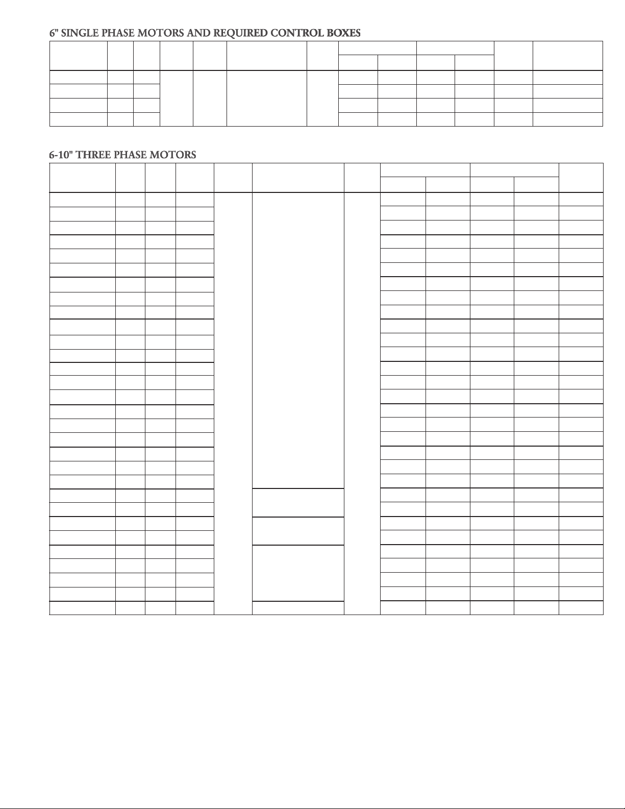
6" SINGLE PHASE MOTORS AND REQUIRED CONTROL BOXES
Order No.
6M051 5 3.7 24 4987 27.5 5735 124 CB05MC (3R)
6M071 7.5 5.5
6M101 10 7.5 50 10135 58 11830 202 CB10MC (3R)
6M151 15 11 72 15180 85 18050 275 CB15MC (3R)
➀ NEMA 3R control boxes will be replacing the current models.
Motor
HP kW Volts Phase
230 1 6” x 6” 1.15
Motor Dia.
vs Flange Dia.
Rated Input Service Factor
S.F.
Amps Watts Amps Watts
36 7675 41 8950 167 CB07MC (3R)
L.R. Control Box
Amps Order No.
6-10" THREE PHASE MOTORS
Motor
Order No.
6M058 5 3.7 200 17.5 4910 19.5 5610 124
6M052 5 3.7 230 15.0 4857 17.0 5520 110
6M054 5 3.7 460 7.5 4857 8.5 5520 55
6M078 7.5 5.5 200 25.4 7180 28.5 8230 158
6M072 7.5 5.5 230 22.0 7127 26.0 8140 144
6M074 7.5 5.5 460 11.0 7127 13.0 8140 72
6M108 10 7.5 200 33.3 9360 37.2 10700 236
6M102 10 7.5 230 29.0 9407 33.0 10730 208
6M104 10 7.5 460 14.5 9407 16.5 10730 104
6M158 15 11 200 47.4 13700 53.5 15710 347
6M152 15 11 230 3 6" x 6" 1.15 42.0 13700 46.0 15800 320
6M154 15 11 460 21.0 13700 23.0 15800 160
6M208 20 15 200 61.2 18040 69.5 20820 431
6M202 20 15 230 54.0 17930 60.0 20650 392
6M204 20 15 460 27.0 17930 30.0 20650 196
6M258 25 18.5 200 77.3 22740 87.5 26190 578
6M252 25 18.5 230 68.0 22470 76.0 25800 530
6M254 25 18.5 460 34.0 22470 37.0 25800 265
6M308 30 22 200 91.8 27000 104.0 31120 674
6M302 30 22 230 82.0 27130 94.0 31160 610
6M304 30 22 460 41.0 27130 47.0 31160 305
6M404 40 30 460
66M504 50 37 460 70.0 45210 79.0 52380 465
86M504 50 37 460
86M604 60 45 460 80.0 52850 90.0 60900 510
8M754 75 55 460 3 1.15 96.0 65900 109.0 76100 650
8M1004 100 75 460
8M1254 125 90 460 160.0 110800 180.0 126000 980
8M1504 150 110 460 195.0 130700 220.0 152000 1060
10M2004 200 150 460 10 "x 10" 235.0 171100 270.0 198600 1260
5-30 HP, 3 Phase 230 and 460 Motors have adjustable voltage feature, change voltage plugs to convert from 230V to 460V
operation. Spare Change Plug Order No's are: PLUG-230V or PLUG-460V.
HP kW Volts Phase
Motor Dia.
vs Flange Dia.
6" x 6"
8" x 6"
8" x 8"
Amps Watts Amps Watts
53.0 35530 60.0 41100 340
65.0 44360 73.0 51000 435
127.0 87600 145.0 101300 795
Rated Input Service Factor
S.F.
L.R.
Amps
➀
13

6" SINGLE PHASE MOTORS
Motor
Order No.
6M051 5 3.7 74.8 G 2.172 0.512 2.627
6M071 7.5 5.5
6M101 10 7.5 73.6 E 1.052 0.316 1.310
6M151 15 11 73.7 D 0.678 0.230 0.850
HP kW Volts Phase
230 1
Efficiency %
F.L.
72.9 F 1.401 0.400 1.774
Resistance - Ohms
KVA
Code
R - Y B - Y R - B
6-10" THREE PHASE MOTORS
Order No.
6M058 5 3.7 200 75.9 K 0.618 50 25
6M052 5 3.7 230 76.8 K 0.806 45 20
6M054 5 3.7 460 76.8 K 3.050 25 10
6M078 7.5 5.5 200 77.9 J 0.504 80 40
6M072 7.5 5.5 230 78.5 J 0.651 70 30
6M074 7.5 5.5 460 78.5 J 2.430 35 15
6M108 10 7.5 200 79.7 K 0.315 100 50
6M102 10 7.5 230 79.3 K 0.448 90 40
6M104 10 7.5 460 79.3 K 1.619 45 20
6M158 15 11 200 81.7 K 0.213 175 70
6M152 15 11 230 81.7 K 0.312 150 60
6M154 15 11 460 81.7 K 1.074 70 30
6M208 20 15 200 82.7 J 0.189 200 90
6M202 20 15 230 83.2 J 0.258 175 70
6M204 20 15 460
6M258 25 18.5 200 82.0 K 0.146 250 110
6M252 25 18.5 230 83.0 K 0.210 225 90
6M254 25 18.5 460 83.0 K 0.666 110 45
6M308 30 22 200 82.9 J 0.119 300 125
6M302 30 22 230 82.5 K 0.166 250 100
6M304 30 22 460 82.5 K 0.554 125 50
6M404 40 30 460 84.0 H 0.446 175 70
66M504 50 37 460 82.5 J 0.388 225 90
86M504 50 37 460 84.1 H 0.331 200 90
86M604 60 45 460 84.7 H 0.278 250 110
8M754 75 55 460 84.9 H 0.218 300 125
8M1004 100 75 460 85.2 H 0.164 400 175
8M1254 125 90 460 84.2 G 0.132 500 225
8M1504 150 110 460 85.6 G 0.115 600 250
10M2004 200 150 460 87.2 F 0.0929 800 350
Motor
HP kW Volts Phase
F.L. KVA Line - Line
Efficiency % Code Resistance
83.2 J 0.861 90 35
3
Time Delay Fuse
Standard Dual Element
14

THREE PHASE POWER UNBALANCE
THREE PHASE POWER UNBALANCE
A full three phase supply consisting of three individual
transformers or one three phase transformer is recommended. “Open” delta or wye connections using only two
transformers can be used, but are more likely to cause poor
performance, overload tripping or early motor failure due to
current unbalance.
Check the current in each of the three motor leads and
calculate the current unbalance as explained below.
If the current unbalance is 2% or less, leave the leads as
connected.
If the current unbalance is more than 2%, current readings
should be checked on each leg using each of the three possible hook-ups. Roll the motor leads across the starter in the
same direction to prevent motor reversal.
Hookup 1 Hookup 2 Hookup 3
Starter Terminals L1 L2 L3 L1 L2 L3 L1 L2 L3
Motor Leads R B Y Y R B B Y R
T3 T1 T2 T2 T3 T1 T1 T2 T3
To calculate percent of current unbalance:
A. Add the three line amp values together.
B. Divide the sum by three, yielding average current.
C. Pick the amp value which is furthest from the average
current (either high or low).
D. Determine the difference between this amp value
(furthest from average) and the average.
E. Divide the difference by the average.
Multiply the result by 100 to determine percent of
unbalance.
Current unbalance should not exceed 5% at service factor
load or 10% at rated input load. If the unbalance cannot be
corrected by rolling leads, the source of the unbalance must
be located and corrected. If, on the three possible hookups,
the leg farthest from the average stays on the same power
lead, most of the unbalance is coming from the power
source.
Contact your local power company to resolve the imbalance.
Example: T3-R = 51 amps T2-Y = 50 amps T1-B = 50 amps
T1-B = 46 amps T3-R = 48 amps T2-Y = 49 amps
T2-Y = 53 amps T1-B = 52 amps T3-R = 51 amps
Total = 150 amps Total = 150 amps Total = 150 amps
÷ 3 = 50 amps ÷ 3 = 50 amps ÷ 3 = 50 amps
— 46 = 4 amps — 48 = 2 amps — 49 = 1 amps
4 ÷ 50 = .08 or 8% 2 ÷ 50 = .04 or 4% 1 ÷ 50 = .02 or 2%
15

TROUBLESHOOTING
TROUBLESHOOTING
WARNING
DISCONNECT AND LOCKOUT ELECTRICAL POWER BEFORE ATTEMPTING ANY SERVICE. FAILURE
TO DO SO CAN CAUSE SHOCK, BURNS OR DEATH.
Hazardous voltage
can shock, burn or
cause death.
Symptom Probable Cause Recommended Action
PUMP MOTOR
NOT RUNNING
1. Motor thermal protector tripped
a. Incorrect control box
b. Incorrect or faulty electrical connections
1. Allow motor to cool, thermal protector will
automatically reset
a – e. Have a qualified electrician inspect and
repair, as required
c. Faulty thermal protector
d. Low voltage
e. Ambient temperature of control box/starter
too high
f. Pump bound by foreign matter
g. Inadequate submergence
f. Pull pump, clean, adjust set depth as required
g. Confirm adequate unit submergence in
pumpage
2. Open circuit breaker or blown fuse
2. Have a qualified electrician inspect and repair,
as required
LITTLE OR
NO LIQUID
DELIVERED
BY PUMP
3. Power source inadequate for load
4. Power cable insulation damage
5. Faulty power cable splice
1. Faulty or incorrectly installed check valve
2. Pump air bound
3. Lift too high for pump
4. Pump bound by foreign matter
5. Pump not fully submerged
6. Well contains excessive amounts of air or gases
3. Check supply or generator capacity
4 – 5. Have a qualified electrician inspect and
repair, as required
1. Inspect check valve, repair as required
2. Successively start and stop pump until flow is
delivered
3. Review unit performance, check with dealer
4. Pull pump, clean, adjust set depth as required
5. Check well recovery, lower pump if possible
6. If successive starts and stops does not remedy,
well contains excessive air or gases
7. Excessive pump wear
8. Incorrect motor rotation – three phase only.
7. Pull pump and repair as required
8. Reverse any two motor electrical leads
16

GOULDS WATER TECHNOLOGY LIMITED WARRANTY
This warranty applies to all water system products manufactured by Goulds Water Technology.
Any part or parts found to be defective within the warranty period shall be replaced at no charge to the dealer during the warranty period. The warranty period shall exist for a
period of twelve (12) months from date of installation or eighteen (18) months from date of manufacture, whichever period is shorter.
A dealer who believes that a warranty claim exists must contact the authorized Goulds Water Technology distributor from whom the pump was purchased and furnish complete
details regarding the claim. The distributor is authorized to adjust any warranty claims utilizing the Goulds Water Technology Customer Service Department.
The warranty excludes:
(a) Labor, transportation and related costs incurred by the dealer;
(b) Reinstallation costs of repaired equipment;
(c) Reinstallation costs of replacement equipment;
(d) Consequential damages of any kind; and,
(e) Reimbursement for loss caused by interruption of service.
For purposes of this warranty, the following terms have these definitions:
(1) “Distributor” means any individual, partnership, corporation, association, or other legal relationship that stands between Goulds Water Technology and the dealer in purchases,
consignments or contracts for sale of the subject pumps.
(2) “Dealer” means any individual, partnership, corporation, association, or other legal relationship which engages in the business of selling or leasing pumps to customers.
(3) “Customer” means any entity who buys or leases the subject pumps from a dealer. The “customer” may mean an individual, partnership, corporation, limited liability company,
association or other legal entity which may engage in any type of business.
THIS WARRANTY EXTENDS TO THE DEALER ONLY.
Xylem, Inc.
2881 East Bayard Street Ext., Suite A
Seneca Falls, NY 13148
Phone: (866) 325-4210
Fax: (888) 322-5877
www.xyleminc.com/brands/gouldswatertechnology
Goulds is a registered trademark of Goulds Pumps, Inc. and is used under license.
© 2012 Xylem Inc. IM103 Revision Number 3 July 2012
17

MANUAL DE INSTRUCCIÓN
IM103
Bombas sumergibles de
5 pulgadas y mayores
INSTRUCCIONES DE INSTALACIÓN Y FUNCIONAMIENTO
18

ÍNDICE
TEMA PÁGINA
Instrucciones de Seguridad .....................................................................................................................................................20
1.0 Cómo prepararse para la instalación ................................................................................................................................. 21
2.0 Instalación mecánica ......................................................................................................................................................... 21
3.0 Instrucciones eléctricas ....................................................................................................................................................22
4.0 Operación de la bomba ....................................................................................................................................................24
5.0 Literatura y manual de instrucciones ................................................................................................................................24
6.0 Accesorios ........................................................................................................................................................................24
Cableado monofásico ...............................................................................................................................................................8
Cableado trifásico .....................................................................................................................................................................9
Datos técnicos ........................................................................................................................................................................25
Trifásico, 4" motores - datos eléctricos ....................................................................................................................................27
Generación II - 3-Alambre, monofásico, 4" motores - datos eléctricos.....................................................................................27
6" motores la monofásico y rectángulos de control requeridos ................................................................................................ 28
6-10” motores trifásicos .........................................................................................................................................................28
6" motores la monofásico .......................................................................................................................................................29
6-10” motores trifásicos .........................................................................................................................................................29
Desbalance de potencia trifásica .............................................................................................................................................30
Identificación y resolución de problemas ................................................................................................................................31
Garantía limitada ....................................................................................................................................................................32
Información del propietario
Información del propietario
Número de modelo de la bomba:
Número de serie de la bomba:
Número de modelo del motor:
Número de serie del motor:
Agente:
No. telefónico del agente:
Fecha de compra:
Fecha de instalación:
Dole® es una registrada de Eaton Corporation.
Cla-Val™ es una marca comercial de Griswold Ind.
19

ADVERTENCIA
ADVERTENCIA
ADVERTENCIA
PRECAUCIÓN
ADVERTENCIA
ADVERTENCIA
ADVERTENCIA
ADVERTENCIA
ADVERTENCIA
PRECAUCIÓN
ADVERTENCIA
ADVERTENCIA
ADVERTENCIA
ADVERTENCIA
PRECAUCIÓN
INSTRUCCIONES DE SEGURIDAD
PARA EVITAR LESIONES PERSONALES GRAVES O AÚN FATALES Y SERIOS DAÑOS MATERIALES, LEA Y SIGA TODAS LAS INSTRUCCIONES DE SEGURIDAD EN EL MANUAL Y EN LA BOMBA.
ESTE MANUAL HA SIDO CREADO COMO UNA GUÍA PARA LA INSTALACIÓN Y OPERACIÓN DE ESTA UNIDAD Y
SE DEBE CONSERVAR JUNTO A LA BOMBA.
Éste es un SÍMBOLO DE ALERTA DE SEGURIDAD. Cuando vea este símbolo en la bomba o en el manual,
busque una de las siguientes palabras de señal y esté alerta a la probabilidad de lesiones personales o daños
materiales.
PELIGRO
AVISO: INDICA INSTRUCCIONES ESPECIALES QUE SON MUY IMPORTANTES Y QUE SE DEBEN SEGUIR DE
RETROCESO DE DRENAJE; ESTOS SISTEMAS DEBEN UTILIZAR OTROS MEDIOS FRANKLIN ELECTRIC
O EN UN MANUAL DEL CÓDIGO N.E.C. (CÓDIGO ELÉCTRICO NACIONAL DE LOS ESTADOS UNIDOS).
EXAMINE BIEN TODAS LAS INSTRUCCIONES Y ADVERTENCIAS ANTES DE REALIZAR CUALQUIER TRABAJO EN
ESTA BOMBA.
MANTENGA TODAS LAS CALCOMANÍAS DE SEGURIDAD.
Aviso importante: Lea las instrucciones de seguridad antes de proseguir con el cableado.
del código deben ser dirigidas al inspector eléctrico local. Si se hace caso omiso a los códigos eléctricos y normas de seguridad de
OSHA, se pueden producir lesiones personales o daños al equipo. Si se hace caso omiso a las instrucciones de instalación del fabricante, se puede producir electrochoque, peligro de incendio, lesiones personales o aún la muerte, daños al equipo, rendimiento insatisfactorio y podría anularse la garantía del fabricante.
pozo debe contar con ventilación de acuerdo con los códigos locales.
En lugares con líquidos inflamables o donde pudiesen pudiese haber gases inflamables sólo deben usarse bombas específicamente
clasificadas para áreas de Clase 1, División 1. Consulte los boletines de catálogos de bombas específicas o la placa de identificación de
la bomba con respecto a las listas de agencias.
bomba demasiado caliente rearranque inesperadamente.
carse con colores para facilitar el mantenimiento y la identificación y resolución de problemas.
PELIGRO
Advierte los peligros que CAUSARÁN graves lesiones personales, la muerte o daños materiales mayores.
Advierte los peligros que PUEDEN causar graves lesiones personales, la muerte o daños materiales mayores.
Advierte los peligros que PUEDEN causar lesiones personales o daños materiales.
Todo el trabajo eléctrico debe ser realizado por un técnico calificado. Siempre siga el Código Eléctrico Nacional (NEC)
o el Código Eléctrico Canadiense, además de todos los códigos locales, estatales y provinciales. Las preguntas acerca
Las unidades estándar fueron diseñadas para bombear agua potable de pozos y tanques de almacenaje. No fueron
di-señadas para su uso en piscinas, cuerpos abiertos de agua, líquidos peligrosos o donde existan gases inflamables. El
Desconecte y bloquee la corriente eléctrica antes de instalar o dar servicio a cualquier equipo eléctrico. Muchas
bombas están equi-padas con protección automática contra la sobrecarga térmica, la cual podría permitir que una
No levante ni transporte ni cuelgue la bomba de los cables eléctricos. El daño a los cables eléctricos puede producir
electrochoque, quemaduras o aún la muerte.
Use únicamente alambre trenzado de cobre para la bomba/motor y la conexión a tierra. El alambre de conexión a
tierra debe ser al menos del mismo tamaño que los alambres de la fuente de alimentación. Los alambres deben codifi-
Instale los cables y la conexión a tierra de acuerdo con el Código Eléctrico Nacional de EE.UU. (NEC) o el Código
Eléctrico Canadiense, además de los códigos locales, estatales y provinciales.
Instale un desconectador de todos los circuitos donde el código lo requiera.
PELIGRO
20
La tensión y fase de la fuente de alimentación deben corresponder con todos los requerimientos del equipo. La tensión
o fase incorrecta puede producir incendio, daño al motor o a los controles y anula la garantía.
Todos los controles trifásicos (3Ø) para bombas sumergibles deben incluir protección contra sobrecarga de Clase 10,
de disparo rápido.
Todos los empalmes deben ser impermeables. Si utiliza juegos de empalme, siga las instrucciones del fabricante.
Seleccione una caja de conexiones NEMA del tipo correcto para la aplicación y ubicación. La caja de conexiones debe
garantizar conexiones de cableado seguras y secas.
La falla de conectar a tierra permanentemente la bomba, el motor y los controles, antes de conectar la corriente
eléctrica, puede causar electrochoque, quemaduras o la muerte.
Asegure un enfriamiento adecuado del motor, ver Tabla 3, cuadro de Velocidades Mínimas de Flujo en la Sección
Técnica.
Esta bomba se evaluó para uso con Agua Únicamente.
Nunca sobrepresurice un tanque de almacenaje a una presión superior a la presión máxima permitida para el
tanque. El hacerlo dañará el tanque, anula la garantía y puede crear un peligro grave.

1.0 CÓMO PREPARARSE PARA LA INSTALACIÓN
1.0 CÓMO PREPARARSE PARA LA INSTALACIÓN
El pozo debe estar desarrollado (limpio) y desinfectado antes
de instalar la bomba.
Escriba el número de modelo y el número de serie de la
bomba y el número de serie del motor en los espacios proporcionados en este Manual de Instrucciones (IOM). Deje el
Manual de Instrucciones completado adjunto al tanque o a
la caja de control en un área seca o entréguelo al propietario.
Adjunte su tarjeta.
Verifique que la tensión del motor, la tensión de control, la
tensión de la bobina (arrancadores trifásicos) y la tensión
de la fuente de alimentación correspondan. La instalación
eléctrica debe ser realizada por personal calificado.
Inspeccione todos los componentes para verificar que no
hayan sido dañados durante el envío y para asegurar que
tenga todos los componentes requeridos: extremo de agua
de la bomba, motor, caja de control del motor monofásico
o arrancador trifásico con sobrecargas, tanque de presión,
interruptor por caída de presión, alambre de cobre, válvula
de alivio de presión (si se requiere), mecanismo antitorsión
(si se requiere), tubería y accesorios.
2.0 CONJUNTO MECÁNICO – bomba y tuberías
2.0 CONJUNTO MECÁNICO – bomba y tuberías
2.1 Sistemas típicos
Bomba en “lata”
Figura 3
Bomba con camisa de flujo en el tanque
Figura 4
Figura 1
Figura 2
Bomba con camisa de flujo en un pozo de diámetro grande
Figura 5
Bomba horizontal en “lata”
Figura 6
21

2.2 Conexión del extremo de la bomba al motor
Quite el protector de cable de la bomba (extremo del agua).
Instale el deflector de arena del eje del motor si se incluye con
el extremo del agua en el paquete de accesorios de montaje
del motor. Conecte el extremo del agua al motor. Alinee los
alambres en el protector de cable y reinstálelo en el extremo
del agua.
La bomba no debe hacerse funcionar seca bajo ninguna
circunstancia. Under no circumstances should the pump be
run dry, doing so may damage internal parts. Sugerimos que
verifique la rotación en un motor trifásico antes de conectarlo
al extremo del agua (bomba). Todos los motores monofásicos
de 4 pulgadas y 6 pulgadas deben rotar en sentido contrahorario cuando se observan desde el extremo del eje. La rotación
en los motores trifásicos debe corresponder con las especificaciones de la bomba. Debido a la alta torsión de arranque, el
motor debe sujetarse de manera que no gire, pero sin dañarse.
2.3 Instalación de la(s) válvula(s) de retención
Las cabezas de descarga están roscadas con roscas de tubo
NPT. Todos los modelos necesitan una válvula de retención a
resorte a menos de 25 pies (7.5 m) de la descarga de la bomba
y debajo del nivel de descenso del suministro de agua. Los
fabricantes de motores recomiendan válvulas de retención adicionales cada 200 a 250 pies (70 m) en la tubería de descarga
vertical. Las válvulas de retención se utilizan para retener la
presión en el sistema e impedir el contragiro, el ariete hidráulico y el empuje hacia arriba.
Contragiro es permitir que el flujo se devuelva por la bomba
para drenar el sistema. Hace que los impulsores y el rotor del
motor giren en dirección inversa. Esto puede producir un desgaste prematuro del cojinete de empuje y si el motor arranca
durante el contragiro, el eje puede torcerse o romperse.
Se produce ariete hidráulico cuando la válvula de retención
más baja está más de 30 pies por encima del nivel del agua
en reposo o si la válvula de retención inferior tiene una fuga
y la válvula de retención de arriba la aguanta. Esto crea un
vacío parcial (espacio) en la tubería de descarga. Durante el
arranque siguiente, el agua moviéndose a una velocidad muy
alta llena el espacio y golpea la válvula de retención cerrada y
el agua estacionaria en el tubo sobre la misma, produciendo
un choque hidráulico. Este choque (ariete hidráulico) puede
partir los tubos, romper las juntas y dañar la bomba y el motor. El ariete hidráulico es un ruido que se detecta fácilmente.
Cuando se descubra, la bomba debe apagarse de inmediato y
debe contactarse al instalador para que solucione el problema.
Empuje hacia arriba es un movimiento ascendente de los
impulsores y eje del motor. Se produce al arrancar la bomba
con cero carga debido a que no hay válvula de retención o a
una fuga en dicha válvula; o a una carga muy baja del sistema
debido a un alto nivel de agua estática. El empuje hacia arriba
recurrente puede producir una falla prematura de la bomba o
el motor o ambos. Consulte 4.2
2.4 Instalación de la bomba en el pozo
Si está utilizando un mecanismo antitorsión, instálelo de acuerdo con las instrucciones de instalación del fabricante. En los
pozos de alimentación superior o pozos de diámetro grande
donde la velocidad del agua no enfría correctamente el motor,
instale una camisa de flujo sobre la bomba. Consulte la Tabla 3
– flujo de enfriamiento requerido.
Conecte la tubería de descarga a la cabeza de descarga de
la bomba. Las bombas sumergibles son capaces de producir
presiones de descarga muy altas, consulte con su proveedor de
tuberías para determinar cuál es el mejor material y especificación para cada instalación.
22
Baje la bomba al interior del pozo. Coloque la bomba al
menos a 10 pies del fondo, pero sobre las rejillas. Proteja los
alambres para que no rocen contra el revestimiento del pozo.
Instale un adaptador sin depresión o un dispositivo similar en
el cabezal del pozo. Consulte con el fabricante del accesorio o
con el proveedor del adaptador con respecto a instrucciones
específicas de instalación.
Utilice cinta aislante impermeable o amarras para alambres
para sujetar los alambres al tubo de bajada a intervalos de 10
pies. Asegúrese de que la cinta no se suelte ya que bloqueará la
succión de la bomba si cae dentro del pozo.
2.5 Válvula de alivio de presión
Se requieren válvulas de alivio de presión en cualquier sistema
que sea capaz de producir más de 100 lbs./pulg. cuadrada
o 230 pies de carga dinámica total. En un área donde una
purga o fuga de agua podría dañar la propiedad, conecte una
línea de drenaje a la válvula de alivio de presión. Tiéndala a
un drenaje adecuado o a un área donde el agua no dañará la
propiedad.
2.6 Tanque de presión e interruptor por caída de
presión (si se usa)
El interruptor por caída de presión debe situarse en la doble
T del tanque en instalaciones de un solo tanque y lo más cerca
posible del centro en instalaciones de varios tanques. Las instalaciones de varios tanques deben tener un tubo de distribución
cuyo tamaño sea 1½ a 2 veces el tamaño del tubo de suministro de la bomba. Esto es para reducir la pérdida de carga por
fricción o el diferencial de presión en el múltiple. Las pérdidas
excesivas pueden producir chasquido del interruptor. No debe
haber filtros o accesorios de pérdida alta entre el interruptor
y el (los) tanque(s). Se permite instalar válvulas de compuerta
completamente abiertas entre el tanque y el interruptor.
2.7 Cómo ajustar la precarga del tanque (si se usa)
Asegure que no haya nada de agua en el tanque. Utilice un
indicador de presión de alta calidad para medir la presión de
precarga del tanque. La presión debe ser 2 lbs./pulg. cuadrada
menos que la presión de conexión (activación) de la bomba.
Como ejemplo, un sistema de 30-50 lbs./pulg. cuadrada utilizaría una precarga del tanque de 28 lbs./pulg. cuadrada.
Seleccione un área que siempre esté a más de 34ºF en la cual
instalar el tanque, el interruptor por caída de presión y la válvula de alivio de presión. El tanque debe estar situado en un
área donde una fuga no produzca daños materiales.
3.0 INSTRUCCIONES ELÉCTRICAS
3.0 INSTRUCCIONES ELÉCTRICAS
3.1 Generalidades
Nota: No energice la unidad ni haga funcionar la bomba hasta
que se hayan completado todas las conexiones eléctricas y de
plomería y la bomba esté llena con agua.
Siempre siga las instrucciones del Código Eléctrico (N.E.C.) de
los Estados Unidos o del Código Eléctrico Canadiense, además
de todos los códigos estatales, provinciales o locales.
Todo el trabajo eléctrico debe ser realizado por personal calificado. Algunas leyes locales requieren que la instalación sea
realizada por “instaladores licenciados” únicamente.
Sugerimos usar únicamente cable de cobre. Utilice el tamaño
de cable que figura en nuestro Manual de Aplicación e Instalación de ITT MAID, o en un manual de Código Eléctrico
Nacional (N.E.C. – National Electric Code). En caso de
discrepancias, prevalecen el N.E.C. en EE.UU., y en Canadá,
el Código Eléctrico Canadiense (Canadian Electrical Code).

3.2 Empalme del cable de bajada a los conductores
del motor
Cuando deba empalmarse o conectarse el cable de bajada
a los conductores del motor, es necesario que el empalme
sea imper-meable. El empalme puede realizarse con juegos
de contracción por calor, accesorios de compresión o cinta
impermeable. Haga corresponder los conductores del motor
con el cable de bajada de acuerdo con los códigos de colores
o identifique los alambres del cable de bajada para asegurar la
conexión apropiada en la caja de control.
A. Instrucciones de empalme con un juego de contracción
por calor
Para utilizar un juego típico de contracción por calor: pele
½ pulgada de los alambres del motor y de los alambres del
cable de bajada; es mejor escalonar los empalmes. Coloque los tubos de contracción por calor sobre los alambres.
Coloque los plegadores sobre los alambres y pliegue los
extremos. Deslice los tubos de contracción por calor sobre
los plegadores y caliéntelos desde el centro hacia afuera.
El sellador y el adhesivo saldrán por los extremos cuando
el tubo se contrae. El tubo, los plegadores, el sellador y el
adhesivo crearán un sello impermeable muy resistente. El
calentamiento excesivo puede quemar los tubos de
contracción por calor.
B. Instrucciones de empalme con cinta
1) Pele el aislamiento del conductor individual sólo lo
necesario para dejar espacio para un conector tipo estaca.
Se prefieren los conectores tubulares tipo estaca. Si el D.E.
del conector no es tan grande como el aislamiento del
cable, auméntelo con cinta aislante de caucho.
2) Encinte las juntas individuales con cinta aislante de
caucho, empleando dos capas; la primera extendiéndose
dos pulgadas más allá de cada extremo de aislamiento del
conductor, la segunda capa extendiéndose dos pulgadas
más allá de la primera capa. Envuelva en forma apretada,
eliminando los espacios de aire lo más posible.
3) Aplique cinta aislante Scotch #33 o equivalente sobre
la cinta aislante de caucho, empleando dos capas como en
el paso “B” y haciendo que cada capa se superponga al
menos dos pulgadas al extremo de la capa anterior.
C. Juegos de empalme por compresión
Consulte las instrucciones suministradas con los juegos de
empalme por compresión o consulte con su proveedor
local.
3.3 Cómo montar la caja de control del motor
Las cajas de control monofásicas trifilares cumplen con los
requerimientos de U.L. para las cubiertas tipo 3R. Son
adecuadas para montaje vertical en lugares interiores o exteriores. Funcionarán a temperaturas entre 14°F (-10°C) y 122°
(50°C). Seleccione un lugar sombreado y seco para montar la
caja. Asegure que haya suficiente espacio para quitar la tapa.
3.4 Verificación de la tensión
Asegure que la tensión del motor y la tensión de la fuente
de alimentación sean iguales. Las bobinas de arrancadores
trifásicos son muy sensibles a la tensión; sugerimos que
siempre verifique la tensión de suministro actual con un
voltímetro. La alta o baja tensión dañará los motores y
controles y eso no está cubierto por la garantía.
3.5 Apague la fuente de alimentación
Utilice un interruptor de desconexión cuando el código así
lo requiera. Apague el cortacircuitos y trabe el interruptor de
desconexión en la posición apagada para impedir el arranque
accidental de la bomba antes que usted esté listo.
3.6 Conexión a una caja de control monofásica
(1ø) o a un arrancador trifásico (3ø)
PELIGRO
No energice la unidad ni haga funcionar la bomba hasta que
haya completado todas las conexiones eléctricas y de tuberías.
Excepción – para verificar la rotación del motor trifásico, es
aceptable energizar el motor antes de conectarlo al extremo del
agua para comprobar la rotación correcta. ¡Después de verificar la rotación, trabe el desconector o el cortacircuitos en la
posición APAGADA!
Verifique que el desconector o cortacircuitos esté APAGADO
antes de hacer cualquier conexión a la fuente de alimentación.
Siempre siga las instrucciones del Código Eléctrico (N.E.C.) de
los Estados Unidos o del Código Eléctrico Canadiense, además
de todos los códigos estatales, provinciales o locales.
A. Cableado de la caja de control trifilar monofásica (1ø)
PRECAUCIÓN
Conecte los conductores del motor codificados con colores a
los terminales de la caja de control del motor - Y (amarillo),
R (rojo) y B (negro) y el alambre verde o desnudo al tornillo
verde de puesta a tierra.
Conecte los alambres entre los terminales de carga en el interruptor por caída de presión y los terminales L1 y L2 de la
caja de control. Conecte un alambre de puesta a tierra entre
la tierra del interruptor y la tierra de la caja de control.
Consulte la Figura 7 u 8
B. Cableado del arrancador trifásico (3ø)
PRECAUCIÓN
Conecte los conductores del motor a T1, T2 y T3 en el
arrancador trifásico. Conecte el alambre de puesta a tierra al
tornillo de puesta a tierra en la caja del arrancador. Siga las
instrucciones del fabricante del arrancador para conectar el
interruptor por caída de presión (cuando se use) al arrancador. Consulte la Figura 9 ó 10
3.7 Conexión de la fuente de alimentación
PRECAUCIÓN
Suministre un circuito derivado separado con fusible o protegido con un cortacircuitos para la bomba. Instale un interruptor
de desconexión principal a plena vista y fácilmente accesible
desde la ubicación del tanque e interruptor de presión.
Monofásica:
Con interruptor por caída de presión – haga la conexión desde
los terminales de línea de dicho interruptor al interruptor de
desconexión (cuando se use) y luego al panel de cortacircuitos.
Sin interruptor por caída de presión – haga la conexión desde
los terminales L1 y L2 de la caja de control al interruptor de
desconexión (cuando se use) y luego al panel de cortacircuitos.
Instalaciones trifásicas – haga las conexiones entre L1, L2, L3 y
tierra en el arrancador al interruptor de desconexión y luego al
panel de cortacircuitos.
23

Los motores sumergibles trifásicos requieren protección de
sobrecarga Quick-Trip de la Clase 10. Use arrancadores NEMA
Clase 14 de Furnas con sobrecargas de la Clase 10 ajustables
ESP100. También se puede utilizar arrancadores de la Clase 16
de Furnas con calentadores “K” (sobrecargas) que se instalan
en el arrancador. Los calentadores “K” deben comprarse por
separado. Consulte el manual ITT MAID o F.E. AIM para otros
dispositivos de protección de carga aceptables.
Nota: Cuando reemplace una turbina de eje de línea u otro tipo
de bomba sobre el suelo con un tipo sumergible, debe cambiar
las sobrecargas Clase 20 en el arrancador a Clase 10 de disparo rápido para obtener una protección adecuada contra las
sobrecargas del motor. El uso de sobrecargas Clase 20 anula la
garantía de la bomba sumergible.
Deben verificarse las instalaciones trifásicas con respecto a la
rotación del motor y al desbalance de fase. Para invertir la rotación del motor, cambie (invierta) dos conductores de alimentación cualquiera. Consulte las instrucciones para identificar el
desbalance trifásico en la Sección Técnica de este manual. Si no
se revisa y corrige el desbalance trifásico, se puede producir una
falla prematura del motor o un disparo falso por sobrecarga.
4.0 FUNCIONAMIENTO DE LA BOMBA
4.0 FUNCIONAMIENTO DE LA BOMBA
4.1 Estrangulación de la descarga durante la
puesta en marcha
Si se arrancará u operará la bomba con una descarga “abierta”,
se debe regular el flujo de la descarga antes del arranque. Instale
una válvula de bola, de globo o Cla-valve® en la línea de descarga. Abra la válvula hasta que esté aproximadamente 1⁄3 abierta
al poner en marcha el sistema. Esto evitará el daño por empuje
hacia arriba a los cojinetes del motor y de la bomba. Puede
abrir la válvula cuando obtenga un flujo adecuado y constante
de agua. No exceda el intervalo de funcionamiento máximo en
gpm indicado en la curva de la bomba. Si no conoce los gpm
máximos para la bomba, llame al distribuidor que se la vendió.
Una causa importante de falla prematura es arrancar o hacer
funcionar una bomba con poco o nada de carga.
4.2 Estrangulación de un pozo de alto nivel
estático para evitar el empuje hacia arriba
Un pozo con un alto nivel estático de agua podría permitir que
la bomba funcione fuera de la curva a la derecha o fuera del
“intervalo recomendado” mostrado en la curva de la bomba.
Recomendamos utilizar un restrictor de flujo “Dole®” o estrangular la descarga con una válvula de bola para evitar el daño por
empuje hacia arriba a la bomba y al motor. El flujo máximo debe
estar dentro del intervalo de funcionamiento recomendado de la
bomba. Si utiliza una válvula de bola, ajústela y quite la manija;
encinte la manija al tubo. Etiquete la válvula con una nota
diciendo “No abrir esta válvula o podrían ocasionarse daños a
la bomba”. Usted puede ajustar la válvula instalando un manómetro entre el pozo y la válvula y estrangulando el flujo/carga
a un valor dentro del intervalo recomendado. También puede
estrangular determinando la velocidad de flujo real; consulte
“Cómo determinar las velocidades de flujo” en la Sección Técnica del catálogo.
4.3 Arranque de la bomba
Abra parcialmente una válvula (llave o drenaje de la caldera) en
el sistema y coloque el cortacircuitos en la posición de ENCENDIDO. Deje que la bomba funcione hasta que el agua salga
clara. En los sistemas trifásicos, verifique la rotación; la rotación
correcta producirá el flujo y presión más altos.
Mida la corriente y verifique que esté dentro del rango de amperios especificado en la hoja de datos del motor o en la placa
de identificación del motor. El valor de la corriente en amperios
debe estar entre los amperios de entrada nominal y los amperios
del factor de servicio. Una corriente alta puede ser causada
por baja o alta tensión. Anote las lecturas de corriente en este
manual, junto con los números de modelos y números de serie
del motor y la bomba. En todos los sistemas trifásicos debe
realizarse una prueba de desbalance trifásico para asegurar una
fuente de alimentación balanceada. Deje una copia de la hoja de
trabajo de desbalance trifásico con este Manual de instalación y
funcionamiento en el sitio del proyecto para referencia futura.
En los sistemas de tanque/interruptor por caída de presión
únicamente – cierre la válvula cuando el agua salga clara y
deje que se acumule presión. Si está ajustado correctamente, el
interruptor debe apagar la bomba a la presión preestablecida.
Abra algunas salidas y deje que la bomba funcione durante unos
pocos ciclos. Compruebe el funcionamiento del interruptor y
verifique que los valores de presión sean los correctos. Revise
todos los accesorios para detectar fugas.
En los sistemas manuales, apague la bomba.
5.0 DOCUMENTACIÓN Y EL MANUAL DE
5.0 DOCUMENTACIÓN Y EL MANUAL DE
INSTRUCCIONES (IOM)
INSTRUCCIONES (IOM)
Entregue al propietario este manual de instrucciones y su
tarjeta. ¡Una etiqueta con su nombre y número de teléfono en
el tanque o en la caja de control es una buena herramienta de
venta para los negocios futuros!
Felicitaciones por haber finalizado la instalación profesional de
una bomba sumergible.
6.0 ACCESORIOS
6.0 ACCESORIOS
Tanques de presión
Los tanques deben dimensionarse para permitir que las bombas de más de dos (2) HP funcionen al menos 2 minutos. Si el
promedio de la bomba es 80 gpm, se requieren tanques con un
“descenso” de nivel de 160 galones. Consulte su catálogo de
Productos para Agua con respecto a los datos de los tanques de
presión.
Protección contra el bajo nivel de agua
Se debe agregar protección para nivel bajo de agua al sistema
en los pozos de bajo rendimiento. Comuníquese con su
distribuidor para obtener información sobre dispositivos de
protección para bajo nivel de agua SymCom.
Paneles eléctricos
El Departamento de Servicio a los Clientes cotizará los paneles
de control de bombas de acuerdo con las especificaciones del
cliente. Favor enviar las especificaciones del panel por escrito
a su distribuidor autorizado. Ellos las enviarán al Grupo
de Servicio al Cliente que apoya su línea de productos. Las
especificaciones escritas deben incluir la potencia de la bomba,
tensión, fase, tipo de gabinete NEMA deseado, secuencia de
funcionamiento, opciones especiales necesarias y una breve
declaración describiendo cualquier lógica especial para alarmas,
cronómetros o características de duplicación. Se recomienda
incluir el nombre y número de teléfono de una persona que
actúe como contacto para contestar preguntas, y esto además
acelerará la cotización.
24

Datos técnicos
Datos técnicos
LECTURAS DE RESISTENCIA DEL AISLAMIENTO DEL MOTOR
Lecturas normales en ohmios/megaohmios, TODOS los motores, entre todos los conductores y tierra
PRECAUCIÓN
Para realizar la prueba de resistencia de aislamiento, abra el cortacircuitos y desconecte todos los conductores
de la caja de control QD o del interruptor por caída de presión. Conecte un conductor del ohmiómetro a cualquier conductor del motor y otro a un tubo de bajada de metal o a una tierra adecuada. Escala R x 100K
Condición del motor y los conductores Valor en OHMIOS Valor en Megaohmios
Motor nuevo, sin cable de alimentación 20,000,000 (o más) 20.0
Motor usado, el cual puede reinstalarse en el pozo 10,000,000 (o más) 10.0
Motor en el pozo – lecturas del cable de alimentación más el motor
Motor nuevo 2,000,000 (o más) 2.0
El motor está en relativamente buenas condiciones 500,000 a 2,000,000 0.5 – 2.0
El motor podría estar dañado o con cable de alimentación dañado
No retire el motor por estas razones
Motor definitivamente dañado o con cable de alimentación dañado
Retire y repare el motor
Falla del motor o del cable de alimentación
Retire y repare el motor
Tamaño del generador
Tamaño del generador
Nota: Siempre consulte al fabricante del generador cuando
surjan dudas.
Estos cuadros de tamaños son recomendaciones basadas en
carga de factor de servicio de motor para generadores típicos
de funcionamiento continuo. Si necesita llamar al fabricante
del generador, esté preparado para informarle el código KVA
del motor, el amperaje de factor de servicio, amperaje de rotor
bloqueado, fase, hertz, tipo de motor, etc.
Se necesita saber qué tipo de generador tiene antes de utilizar
los cuadros, ya que el tamaño de generador requerido varía
según el tipo. También se llaman a los generadores regulados
internamente autoexcitados. Los generadores regulados
externamente son los más comunes. Además de la clasificación
Recomendaciones para generadores
Recomendaciones para generadores
Menos de 10,000 0 – 0.01
de Kw/KVA, es muy importante la frecuencia del generador
(Hertz, típicamente 60 Hz en EE.UU.) al operar equipos de
bombeo, ya que las variaciones de frecuencia afectan la salida
de la bomba en relación directa con las Leyes de Afinidad de
la bomba. El funcionamiento con menos de 60 hertz reducirá
el flujo y carga de agua, mientras que el funcionamiento con
más de 60 hertz aumentará el flujo, carga de agua, HP y tiro de
amperaje y podría sobrecargar el motor.
Siempre se debe arrancar el generador antes de arrancar la
bomba/motor y siempre apagar la bomba/el motor antes de apagar el generador. La operación de generadores en elevaciones
mayores o utilizar gas natural como combustible pueden afectar
el desempeño; consulte al fabricante del generador para obtener
sus recomendaciones en estos casos.
20,000 a 500,000 0.02 – 0.5
10,000 a 20,000 0.01 – 0.02
Regulado externamente Regulado internamente
Motor HP KW KVA KW KVA
Clasificación mínima del generador
.5 2 2.5 1.5 1.9
.75 3 3.8 2 2.5
1 4 5 2.5 3.2
1.5 5 6.3 3 3.8
2 7.5 9.4 4 5
3 10 12.5 5 6.3
5 15 18.8 7.5 9.4
7.5 20 25 10 12.5
10 30 37.5 15 18.8
Motores trifilares
15 40 50 20 25
monofásicos y
20 60 75 25 31
trifásicos
25 75 94 30 37.5
30 100 125 40 50
40 100 125 50 62.5
50 150 188 60 75
60 175 220 75 94
75 250 313 100 125
100 300 375 150 188
125 375 469 175 219
150 450 563 200 250
175 525 656 250 313
200 600 750 275 344
25

Datos técnicos (continuación)
Datos técnicos
Capacidad de transformador requerida para
motores sumergibles – monofásicos o trifásicos
Los transformadores de distribución deben estar adecuadamente dimensionados para satisfacer los requerimientos de
KVA del motor sumergible. Si los transformadores son demasiado pequeños para abastecer la carga, hay una reducción
de tensión al motor.
La Tabla 1 hace referencia a la clasificación de potencia del
motor, monofásico y trifásico, los KVA efectivos totales
requeridos y el transformador más pequeño requerido para
sistemas trifásicos abiertos o cerrados. Los sistemas abiertos
requieren transfor-madores más grandes ya que sólo se usan
dos transformadores.
Otras cargas agregarían directamente a los requerimientos de
tamaño de KVA del conjunto de transformadores.
Tabla 1 – capacidad de los transformadores
Clasificación más baja en KVA –
Cada transformador
HP del motor TRIÁNGULO o TRIÁNGULO o
KVA efectivos ESTRELLA abrerta ESTRELLA cerrada
totales requeridos 2 transformadores 3 transformadores
1½ 3 2 1
2 4 2 1.5
3 5 3 2
5 7.5 5 3
7½ 10 7.5 5
10 15 10 5
15 20 15 7.5
20 25 15 10
25 30 20 10
30 40 25 15
40 50 30 20
50 60 35 20
60 75 40 25
75 90 50 30
100 120 65 40
125 150 85 50
150 175 100 60
175 200 115 70
200 230 130 75
NOTA: Los transformadores mostrados son de clasificación de potencia nominal estándar
(KVA). Si la experiencia y práctica de la compañía de electricidad permite una carga del transformador más alta que la clasificación nominal bajo condiciones de operación específicas y
mantiene la tensión y el equilibrio correctos, dichos valores de carga más altos pueden usarse
para que el (los) transformador(es) cumplan con la potencia efectiva total (KVA) requerida.
Posición de montaje
Los motores son adecuados para funcionar en posiciones de
montaje desde el eje vertical hasta horizontal. Si los motores
de 4 pulgadas con una potencia de hasta 2 HP se arrancan
más de 10 veces por día, se recomienda que el eje se incline
hacia arriba en un ángulo de 15º con respecto a la horizontal
para reducir al mínimo el desgaste de la arandela de empuje
hacia arriba debido a la marcha por inercia.
Frecuencia de arranques
El número promedio de arranques por día en un período de
meses o años influencia la vida útil de un sistema de bombeo
sumergible. El ciclado excesivo afecta la vida útil de los componentes de control tales como los interruptores por caída
de presión, arrancadores, relés y condensadores, además de
las estrías y cojinetes. El ciclado rápido también puede causar
calentamiento excesivo y fallas del devanado.
El tamaño de la bomba, el tamaño del tanque y otros
controles deben seleccionarse para mantener el número de
arranques por día lo más bajo posible para prolongar la vida
útil, basado en el número máximo de arranques por día de
24 horas, tal como se muestra en la Tabla 2.
Los motores de más de 2 HP deben dejarse funcionar un
mínimo de 2 minutos para disipar la acumulación de calor
debido a la corriente de arranque.
Tabla 2 – número de arranques
Arranques máximos por día de 24 horas
Clasificación del motor
½ HP a 5 HP 100 300
7½ HP a 30 HP 50 100
40 HP y más — 100
Monofásico Trifásico
Enfriamiento del motor, clasificaciones de
temperatura y duración de funcionamiento
Todo motor CentriPro de 4 pulgadas puede funcionar
continuamente en agua de hasta 86º F. Se logrará una vida
útil optima si se mantiene una velocidad de flujo mínima
después del motor de 0,25 pies por segundo. Use una camisa
de flujo si la velocidad es inferior a 0,25'/seg., si el pozo tiene
alimentación superior o cuando se use la bomba en un gran
cuerpo de agua o tanque grande.
Los motores con diseño encapsulado de seis (6) pulgadas
de 5 – 40 HP funcionarán en agua de hasta 95º F (35º
C), sin ninguna reducción de caballos de fuerza, con una
velocidad de flujo mínima de 0,5 pies/seg. después del motor.
Los motores de 6” de 50 HP y todos los motores de 8” –
10” pueden funcionar en agua de 77º F (25º C) con una
velocidad de 5'/seg. después del motor.
Tabla 3 – Velocidades mínimas de flujo para un
enfriamiento de motor adecuado
Diámetro de Motor CP o FE de CP = Diám. 5,5" CP = Diám. 7.52"
pozo o 4" con diámetro de Motor CP 6" Motor CP 8"
camisa 3,75" 0,25'/seg. 0,5'/seg. 0,5'/seg.
(pulgadas)
4 1.2 – –
5 7 – –
6 13 7 –
7 20 23 –
8 30 41 9
10 50 85 53
12 80 139 107
14 110 198 170
16 150 276 313
Multiplicar gpm por 0,.2271 for m3/Hr.
Multiplicar gpm por 3,785 para 1/min.
GPM requerido
26

Trifásico, 4" Motores - Datos Eléctricos, 60 Hertz, 3450 RPM
Carga completa Factor de servicio
CentriPro # HP kW Voltios SF Amps Watts Amps Watts
M30430 3 2.2
M50430 5 3.7 1.15 18.3 4850 20.2 5515 113 0.4-0.8
200
1.15 10.9 2890 12.0 3290 71 0.9-1.3
Rotor bloqueado
amperios
Línea a línea
resistencia
M75430 7.5 5.5 1.15 27.0 7600 30.0 8800 165 0.5-0.6
M30432 3 2.2
M50432 5 3.7 1.15 15.7 4925 17.5 5650 93 .85-1.25
230
1.15 9.2 2880 10.1 3280 58.9 1.3-1.7
M75432 7.5 5.5 1.15 24 7480 26.4 8570 140 .55-.85
M30434 3 2.2
M50434 5 3.7 1.15 7.6 4810 8.5 5530 48 3.58-4.00
M75434 7.5 5.5 1.15 12.2 7400 13.5 8560 87 1.9-2.3
460
1.15 4.8 2920 5.3 3320 30 5.9-6.5
M100434 10 7.5 1.15 15.6 9600 17.2 11000 110 1.8-2.2
M30437 3 2.2
M50437 5 3.7 1.15 7.0 5080 7.6 5750 55 3.6-4.2
575
1.15 3.7 2850 4.1 3240 21.1 9.4-9.7
M75437 7.5 5.5 1.15 9.1 7260 10.0 8310 55 3.6-4.2
Generación II - 3-Alambre, Monofásico, 4" Motores - Datos Eléctricos, 60 Hertz, 3450 RPM
Carga
completa
Número
Tipo
de
HP kW
Voltios
SF Amps Watts Amps Watts
orden
3-Alambre
con CSCR
(CR) o el
rectángulo
de control
magnético
del
contactor
(bujía
métrica)
¹ Un rectángulo de control de CSCR con un sufijo del CR se puede substituir por una conclusión magnética del modelo del MC.
Y = amarillo, B = negro, R = rojo
M30412 3 2.2
230 1.15
M50412 5 3.7
Y – 14.3
B – 12.0
R – 5.7
Y – 24.0
B – 19.1
R – 10.2
3170
5300
Factor de
servicio
Y – 16.5
B – 13.9
R – 5.6
Y – 27.0
B – 22.0
R – 10.0
Rotor
bloquea-
do am-
perios
3620 76
6030 101
Resistencia
de devanado
Principal
(B-Y)
1.1 -
1.4
.62 -
.76
Ar-
ranque
(R-Y)
2.0 -
2.5
1.36 -
1.66
Rectángulo
de control
requerido
CB30412CR or
CB30412MC
CB50412CR or
CB50412MC
1
27

6" MOTORES LA MONOFÁSICO Y RECTÁNGULOS DE CONTROL REQUERIDOS
Número
de orden
6M051 5 3.7 24 4987 27.5 5735 124 CB05MC (3R)
6M071 7.5 5.5
6M101 10 7.5 50 10135 58 11830 202 CB10MC (3R)
6M151 15 11 72 15180 85 18050 275 CB15MC (3R)
➀ Los rectángulos de control de la nema 3R substituirán los modelos actuales.
HP kW Voltios Fase
230 1 6” x 6” 1.15
Diá. del motor
contra diá. del borde
Entrada de info. clasificada Factor de servicio
S.F.
Amps Watts Amps Watts
36 7675 41 8950 167 CB07MC (3R)
Rotor bloq- Rectángulo de
ueado amps control requerido
6-10” MOTORES TRIFÁSICOS
Número
de orden
6M058 5 3.7 200 17.5 4910 19.5 5610 124
6M052 5 3.7 230 15.0 4857 17.0 5520 110
6M054 5 3.7 460 7.5 4857 8.5 5520 55
6M078 7.5 5.5 200 25.4 7180 28.5 8230 158
6M072 7.5 5.5 230 22.0 7127 26.0 8140 144
6M074 7.5 5.5 460 11.0 7127 13.0 8140 72
6M108 10 7.5 200 33.3 9360 37.2 10700 236
6M102 10 7.5 230 29.0 9407 33.0 10730 208
6M104 10 7.5 460 14.5 9407 16.5 10730 104
6M158 15 11 200 47.4 13700 53.5 15710 347
6M152 15 11 230 3 6" x 6" 1.15 42.0 13700 46.0 15800 320
6M154 15 11 460 21.0 13700 23.0 15800 160
6M208 20 15 200 61.2 18040 69.5 20820 431
6M202 20 15 230 54.0 17930 60.0 20650 392
6M204 20 15 460 27.0 17930 30.0 20650 196
6M258 25 18.5 200 77.3 22740 87.5 26190 578
6M252 25 18.5 230 68.0 22470 76.0 25800 530
6M254 25 18.5 460 34.0 22470 37.0 25800 265
6M308 30 22 200 91.8 27000 104.0 31120 674
6M302 30 22 230 82.0 27130 94.0 31160 610
6M304 30 22 460 41.0 27130 47.0 31160 305
6M404 40 30 460
66M504 50 37 460 70.0 45210 79.0 52380 465
86M504 50 37 460
86M604 60 45 460 80.0 52850 90.0 60900 510
8M754 75 55 460 3 1.15 96.0 65900 109.0 76100 650
8M1004 100 75 460
8M1254 125 90 460 160.0 110800 180.0 126000 980
8M1504 150 110 460 195.0 130700 220.0 152000 1060
10M2004 200 150 460 10 "x 10" 235.0 171100 270.0 198600 1260
5-30 HP, los motores de 3 la fase 230 y 460 tienen característica ajustable del voltaje, cambian los enchufes del voltaje al
convertido de 230V a la operación 460V. Ningunos de orden del enchufe del dinero suelto son: PLUG-230V o PLUG-460V.
HP kW Voltios Fase
Diá. del motor
contra diá. del borde
53.0 35530 60.0 41100 340
6" x 6"
65.0 44360 73.0 51000 435
8" x 6"
127.0 87600 145.0 101300 795
8" x 8"
Entrada de info. clasificada
S.F.
Factor de servicio
Amps Watts Amps Watts
Rotor bloq-
ueado amps
➀
28

6" MOTORES LA MONOFÁSICO
Número
de orden
6M051 5 3.7 74.8 G 2.172 0.512 2.627
6M071 7.5 5.5
6M101 10 7.5 73.6 E 1.052 0.316 1.310
6M151 15 11 73.7 D 0.678 0.230 0.850
Y = amarillo, B = negro, R = rojo
HP kW Voltios Fase
230 1
F.L.
Eficacia %
72.9 F 1.401 0.400 1.774
Código
del KVA
Resistencia - ohmios
R - Y B - Y R - B
6-10” MOTORES TRIFÁSICOS
Número
de orden
6M058 5 3.7 200 75.9 K 0.618 50 25
6M052 5 3.7 230 76.8 K 0.806 45 20
6M054 5 3.7 460 76.8 K 3.050 25 10
6M078 7.5 5.5 200 77.9 J 0.504 80 40
6M072 7.5 5.5 230 78.5 J 0.651 70 30
6M074 7.5 5.5 460 78.5 J 2.430 35 15
6M108 10 7.5 200 79.7 K 0.315 100 50
6M102 10 7.5 230 79.3 K 0.448 90 40
6M104 10 7.5 460 79.3 K 1.619 45 20
6M158 15 11 200 81.7 K 0.213 175 70
6M152 15 11 230 81.7 K 0.312 150 60
6M154 15 11 460 81.7 K 1.074 70 30
6M208 20 15 200 82.7 J 0.189 200 90
6M202 20 15 230 83.2 J 0.258 175 70
6M204 20 15 460
6M258 25 18.5 200 82.0 K 0.146 250 110
6M252 25 18.5 230 83.0 K 0.210 225 90
6M254 25 18.5 460 83.0 K 0.666 110 45
6M308 30 22 200 82.9 J 0.119 300 125
6M302 30 22 230 82.5 K 0.166 250 100
6M304 30 22 460 82.5 K 0.554 125 50
6M404 40 30 460 84.0 H 0.446 175 70
66M504 50 37 460 82.5 J 0.388 225 90
86M504 50 37 460 84.1 H 0.331 200 90
86M604 60 45 460 84.7 H 0.278 250 110
8M754 75 55 460 84.9 H 0.218 300 125
8M1004 100 75 460 85.2 H 0.164 400 175
8M1254 125 90 460 84.2 G 0.132 500 225
8M1504 150 110 460 85.6 G 0.115 600 250
10M2004 200 150 460 87.2 F 0.0929 800 350
HP kW Voltios Fase
F.L. Código Línea a línea
Eficacia % del KVA resistencia
83.2 J 0.861 90 35
3
Fusible de retraso de tiempo
Estándar Elemento dual
29

DESBALANCE DE POTENCIA TRIFASICA
DESBALANCE DE POTENCIA TRIFASICA
Se recomienda un suministro trifásico completo incluyendo
tres transformadores individuales o un transformador trifásico.
Se pueden usar conexiones en estrella o en triángulo “abierto”
empleando sólo dos transformadores, pero hay más posibilidad
de que produzcan un rendimiento inadecuado, disparo por
sobrecarga o falla prematura del motor debido al desbalance de
corriente.
Mida la corriente en cada uno de los tres conductores del motor
y calcule el desbalance de corriente en la forma que se explica
abajo. Si el desbalance de corriente es del 2% o menos, deje los
conductores tal como están conectados.
Si el desbalance de corriente es de más del 2%, hay que verificar
las lecturas de corriente en cada derivación empleando cada
una de las tres conexiones posibles. Enrolle los conductores del
motor en el arrancador en la misma dirección para evitar una
inversión del motor.
Conexión 1 Conexión 2 Conexión 3
Terminales del L1 L2 L3 L1 L2 L3 L1 L2 L3
arrancador
Para calcular el porcentaje de desbalance de corriente:
A. Sume los tres valores de corriente de línea.
B. Divida la suma por tres, con lo cual se obtiene la corri-
ente promedio.
C. Seleccione el valor de corriente más alejado de la corri-
ente promedio (ya sea alto o bajo).
D. Determine la differencia entre este valor de corriente
(más alejado del promedio) y el promedio.
E. Divida la diferencia por el promedio.
Multiplique el resultado por 100 para determinar el
porcentaje de desbalance.
El desbalance de corriente no debe exceder el 5% con la carga
del factor de servicio o el 10% con la carga de entrada nominal.
Si el desbalance no puede corregirse enrollando los conductores, la causa del desbalance debe determinarse y corregirse. Si,
en las tres conexiones posibles, la derivación más alejada del
promedio está en el mismo conductor de potencia, entonces la
mayoría del desbalance proviene de la fuente de potencia.
Contacte a la compañía de electricidad local para solucionar
el desbalance.
Conductores del R B Y Y R B B Y R
motor T3 T1 T2 T2 T3 T1 T1 T2 T3
Ejemplo: T3-R = 51 amperios T2-Y = 50 amperios T1-B = 50 amperios
T1-B = 46 amperios T3-R = 48 amperios T2-Y = 49 amperios
T2-Y = 53 amperios T1-B = 52 amperios T3-R = 51 amperios
Total = 150 amperios Total = 150 amperios Total = 150 amperios
÷ 3 = 50 amperios ÷ 3 = 50 amperios ÷ 3 = 50 amperios
— 46 = 4 amperios — 48 = 2 amperios — 49 = 1 amperios
4 ÷ 50 = .08 u 8% 2 ÷ 50 = .04 ó 4% 1 ÷ 50 = .02 ó 2%
30

Identificación y resolución de problemas
Identificación y resolución de problemas
ADVERTENCIA
DESCONECTE Y BLOQUEE LA CORRIENTE ELÉCTRICA ANTES INTENTAR DAR SERVICIO. DE LO
CONTRARIO, SE PUEDE PRODUCIR ELECTROCHOQUE, QUEMADURAS O LA MUERTE.
Un voltaje peligroso puede
producir golpes el ctricos,
quemaduras o la muerte.
Síntoma Causa probable Acción recomendada
EL MOTOR
DE LA BOMBA
NO ESTÁ
FUNCIONANDO
1. Se disparó el protector térmico del motor
a. Caja de control incorrecta
b. Conexiones eléctricas incorrectas o defectuosas
1. Deje que el motor se enfríe, el protector térmico se
reposicionará automáticamente
a – e. Solicite que un electricista calificado
inspeccione y repare, según sea requerido.
c. Protector térmico defectuoso
d. Baja tensión
e. La temperatura ambiente de la caja de
control/arrancador es demasiado alta
f. La bomba está atascada con materias extrañas
g. Sumersión inadecuada
f. Retire la bomba, límpiela, ajústela, fije la
profundidad según sea requerido
g. Confirme la sumersión adecuada de la unidad
en el líquido a bombearse.
2. Cortacircuitos abierto o fusible quemado
2. Solicite que un electricista calificado inspeccione y
repare, según sea requerido.
LA BOMBA
ENTREGA POCO
O NADA DE
LÍQUIDO
3. La fuente de energía es inadecuada para la carga
4. Daño del aislamiento del cable de alimentación
5. Empalme defectuoso del cable de alimentación
1. Válvula de retención defectuosa o instalada
incorrectamente
2. La bomba está atascada con aire
3. Elevación demasiado alta para la bomba
3. Verifique el suministro o la capacidad del generador
4 – 5. Solicite que un electricista calificado
inspeccione y repara, según sea requerido.
1. Inspeccione la válvula de retención, repárela
según sea necesario
2. Arranque y detenga la bomba sucesivamente
hasta que haya flujo
3. Verifique el rendimiento de la unidad, consulte
con el agente.
4. La bomba está atascada con materias extrañas
4. Retire la bomba límpiela, ajústela, fije la
profundidad según sea requerido
5. La bomba no está completamente sumergida
5. Verifique la recuperación del pozo, baje la
bomba si es posible
6. El pozo contiene demasiado aire o gases
6. Si los arranques y paradas sucesivos no
solucionan el problema, el pozo contiene
demasiado aire o gases
7. Desgaste excesivo de la bomba
8. Rotación incorrecta del motor – unidades
trifásicas únicamente.
7. Retire y repare la bomba, según sea necesario
8. Invierta dos conductores eléctricos cualquiera del
motor
31

GARANTÍA LIMITADA DE GOULDS WATER TECHNOLOGY
Esta garantía corresponde para todos los productos de sistemas de agua fabricados por Goulds Water Technology.
Toda parte o partes que resultaren defectuosas dentro del período de garantía serán reemplazadas durante dicho período de garantía sin cargo para el comerciante. Tal período de
garantía se extiende por doce (12) meses a partir de la fecha de instalación, o dieciocho (18) meses a partir de la fecha de fabricación, la que se cumpla primero.
El comerciante que considere que existe lugar a un reclamo de garantía deberá ponerse en contacto con el distribuidor autorizado de Goulds Water Technology del cual adquiriera la
bomba y brindar información detallada con respecto al reclamo. El distribuidor está autorizado a liquidar todos los reclamos por garantía a través del Departamento de Servicios a
Clientes de Goulds Water Technology.
La presente garantía excluye:
(a) La mano de obra, el transporte y los costos relacionados en los que incurra el comerciante;
(b) los costos de reinstalación del equipo reparado;
(c) los costos de reinstalación del equipo reemplazado;
(d) daños emergentes de cualquier naturaleza; y
(e) el reembolso de cualquier pérdida causada por la interrupción del servicio.
A los fines de esta garantía, los términos “Distribuidor”, “Comerciante” y “Cliente” se definen como sigue:
(1) “Distribuidor” es aquel individuo, sociedad, corporación, asociación u otra entidad jurídica que opera entre Goulds Water Technology y el comerciante para la compra, consig-
nación o contratos de venta de las bombas en cuestión.
(2) “Comerciante” es todo individuo, sociedad, corporación asociación u otra entidad jurídica que realiza negocios de venta o alquiler-venta (leasing) de bombas a los clientes.
(3) “Cliente” es toda entidad que compra o adquiere bajo la modalidad de leasing las bombas en cuestión de un comerciante. El término “cliente” puede significar un individuo,
sociedad, corporación, sociedad de responsabilidad limitada, asociación o cualquier otra entidad jurídica con actividades en cualquier tipo de negocios.
LA PRESENTE GARANTÍA SE EXTIENDE AL COMERCIANTE ÚNICAMENTE.
Xylem, Inc.
2881 East Bayard Street Ext., Suite A
Seneca Falls, NY 13148
Teléfono: (866) 325-4210
Fax: (888) 322-5877
www.xyleminc.com/brands/gouldswatertechnology
Goulds es una marca registrada de Goulds Pumps, Inc. y se utiliza bajo licencia.
© 2012 Xylem Inc. IM103 Revisión Número 3 Julio 2012

MANUEL D'UTILISATION
IM103
Pompes submersibles
de 5 po et plus
DIRECTIVES D’INSTALLATION ET D’UTILISATION

TABLE DES MATIÈRES
SUJET PAGE
Consignes de sécurité .............................................................................................................................................................35
1. Préparatifs d’installation .....................................................................................................................................................36
2. Installation ......................................................................................................................................................................... 36
3. Alimentation électrique ..................................................................................................................................................... 37
4. Mise en service de la pompe ............................................................................................................................................... 39
5. Documentation et manuel ..................................................................................................................................................39
6. Accessoires ......................................................................................................................................................................... 39
Montage monophasé ................................................................................................................................................................ 8
Montage triphasé .....................................................................................................................................................................9
Données techniques ................................................................................................................................................................ 40
Triphasé, 4" moteurs - données électriques ..............................................................................................................................42
Génération II - à 3 fils, le monophasé, 4" moteurs - données électriques .................................................................................42
6" moteurs monophasé et boîtes de contrôle requises .............................................................................................................43
6-10" moteurs triphasés .......................................................................................................................................................... 43
6" moteurs monophasé ...........................................................................................................................................................44
6-10" moteurs triphasés .......................................................................................................................................................... 44
Déséquilibre du courant triphasé ............................................................................................................................................45
Diagnostic des anomalies ........................................................................................................................................................ 46
Garantie limitée ...................................................................................................................................................................... 48
Informations pour le propriétaire
Informations pour le propriétaire
No de modèle de la pompe :
No de série de la pompe :
No de modèle du moteur :
No de série du moteur :
Détaillant :
No de téléphone du détaillant :
Date d’achat :
Date d’installation :
Dole est une marque déposée de la Eaton Corporation.
Cla-Val est une marque de commerce de Griswold Ind.
34

AVERTISSEMENT
AVERTISSEMENT
AVERTISSEMENT
CONSIGNES DE SÉCURITÉ
ATTENTION
AVERTISSEMENT
DANGER
ATTENTION
AVERTISSEMENT
AVERTISSEMENT
AVERTISSEMENT
AVERTISSEMENT
AVERTISSEMENT
AVERTISSEMENT
AVERTISSEMENT
DANGER
AFIN DE PRÉVENIR LES BLESSURES GRAVES OU MORTELLES ET LES DOMMAGES MATÉRIELS IMPORTANTS, LIRE
ET SUIVRE TOUTES LES CONSIGNES DE SÉCURITÉ FIGURANT DANS LE MANUEL ET SUR LA POMPE.
LE PRÉSENT MANUEL A POUR BUT DE FACILITER L’INSTALLATION ET L’UTILISATION DE LA POMPE ET DOIT ÊTRE
CONSERVÉ PRÈS DE CELLE-CI.
Le symbole ci-contre est un SYMBOLE DE SÉCURITÉ employé pour signaler les mots-indicateurs dont on
trouvera la description ci-dessous. Sa présence sert à attirer l’attention afin d’éviter les blessures et les dommages
matériels.
DANGER
AVERTISSEMENT
ATTENTION
AVIS : SERT À ÉNONCER LES DIRECTIVES SPÉCIALES DE GRANDE IMPORTANCE QUE L’ON DOIT SUIVRE.
LIRE SOIGNEUSEMENT CHAQUE DIRECTIVE ET AVERTISSEMENT AVANT D’EFFECTUER TOUT
TRAVAIL SUR LA POMPE.
N’ENLEVER AUCUN AUTOCOLLANT DE SÉCURITÉ.
Avis important : lire les consignes de sécurité avant de procéder au câblage.
specteur en électricité. Le non-respect du code et des politiques de santé et de sécurité au travail peut entraîner des blessures et des dommages matériels. L’inobservation des directives fournies par le fabricant peut se traduire par un choc électrique, un incendie, des blessures
ou la mort, ainsi que par des dommages matériels, des performances non satisfaisantes et l’annulation de la garantie du fabricant.
être aérés selon les codes locaux.
Seules les pompes de classe 1, division 1, peuvent servir pour les liquides dangereux et les endroits pouvant contenir des gaz inflam-
mables. Le nom des organismes de normalisation pertinents figure sur la plaque signalétique des pompes en question ou dans les feuillets
du catalogue décrivant ces pompes.
et le rétablit automatiquement, redémarrant ainsi la pompe inopinément.
faciliter l’entretien et le diagnostic des anomalies.
Prévient des risques qui VONT causer des blessures graves, la mort ou des dommages matériels importants.
Prévient des risques qui PEUVENT causer des blessures graves, la mort ou des dommages matériels importants.
Prévient des risques qui PEUVENT causer des blessures ou des dommages matériels.
L’installation électrique doit être effectuée par un technicien qualifié. Il faut toujours suivre les stipulations du code
provincial ou national de l’électricité pertinent et les règlements locaux. Adresser toute question relative au code à un in-
Les pompes standard sont conçues pour l’eau potable des puits et des réservoirs de stockage, mais non pour l’eau
libre, les piscines, les liquides dangereux ni les endroits pouvant contenir des gaz inflammables. Les puits doivent
Verrouiller la source de courant en position hors circuit avant de procéder à l’installation ou à l’entretien de tout dispositif électrique. Le protecteur thermique de certains moteurs de pompe coupe le courant lorsqu’il y a surcharge thermique
Ne pas lever, transporter ni suspendre la pompe par le câble d’alimentation : l’endommagement du câble pourrait
causer un choc électrique, des brûlures ou la mort.
N’utiliser que du fil de cuivre torsadé pour l’alimentation et la mise à la terre du moteur et de la pompe. Le calibre
du fil de terre doit être au moins égal à celui des fils d’alimentation. Les fils devraient tous être chromocodés pour
Poser le fil de terre et les autres fils suivant les prescriptions du code provincial ou national de l’électricité pertinent
et les règlements locaux.
Installer un sectionneur tout conducteur si le code l’exige.
Le nombre de phases et la tension du courant doivent convenir à tout le matériel. Un nombre de phases et une tension inappropriés annulent la garantie et peuvent causer un incendie et des dommages au moteur et aux commandes.
Les commandes triphasées des pompes submersibles doivent assurer une protection rapide de classe 10 contre la
surcharge.
Chaque jonction de fils doit être étanche. Si l’on emploie un nécessaire de jonction (« kit »), suivre les directives du
fabricant.
Choisir la boîte de jonction du type et de la classe NEMA convenant au type et au lieu d’utilisation. La boîte doit
assurer une jonction de fils sûre et étanche.
Omettre la mise à la terre permanente de la pompe, du moteur et des commandes avant le branchement à la
source de courant peut causer un choc électrique, des brûlures ou la mort.
Veiller à bien refroidir le moteur (v. la table 3 et Température et vitesse d’écoulement de l’eau).
La pompe submersible a été évaluée pour le pompage de l’eau seulement.
Ne jamais dépasser la pression nominale maximale du réservoir de stockage pour ne pas endommager celui-ci,
annuler la garantie ni causer de graves dangers.
35

1. PRÉPARATIFS D’INSTALLATION
1. PRÉPARATIFS D’INSTALLATION
Avant l’installation de la pompe, on devrait nettoyer et
désinfecter le puits et en maximiser le débit par surpompage.
Inscrire les numéros de modèle et de série de la pompe et du
moteur et les autres renseignements pertinents à la rubrique
« Informations pour le propriétaire », dans le manuel. Agrafer
sa carte d’affaires au manuel et attacher ensuite celui-ci au
réservoir ou à la boîte de commande, dans un endroit sec, ou
le remettre au propriétaire.
S’assurer que la tension de la bobine (démarreurs triphasés)
et d’entrée du moteur ainsi que les tension de commande et
d’alimentation correspondent. L’installation électrique doit
être réalisée par du personnel qualifié.
Inspecter tous les composants pour s’assurer qu’ils n’ont pas
été endommagés pendant le transport et qu’il n’en manque
pas : tête de pompage et moteur, boîte de commande du
moteur monophasé ou démarreur triphasé à limiteurs de
surcharge, réservoir à pression, pressostat (manostat), câble
à fils en cuivre, soupape de décharge (si requise), dispositif
antitorsion (si requis), tuyau ainsi que raccords et accessoires
de tuyauterie.
2. INSTALLATION
2. INSTALLATION
2.1. Installations types
Pompe en cuve d’aspiration (« can »)
Figure 3
Figure 1
Pompe avec manchon d’accélération de l’écoulement,
en réservoir
Figure 4
Pompe avec manchon d’accélération de l’écoulement,
en puits de grand diamètre
Figure 5
36
Pompe à l’horizontale en cuve d’aspiration
Figure 6
Figure 2

2.2. Fixation de la tête de pompage au moteur
Ne jamais faire fonctionner la pompe à sec afin de ne pas en
endommager les pièces internes. Pour les moteurs triphasés, il
est suggéré de vérifier s’ils tournent dans le sens spécifié pour la
pompe avant de les fixer à cette dernière. Les moteurs monophasés de 4 et de 6 po devraient tourner en sens antihoraire, vus
du bout de l’arbre. En raison du fort couple de démarrage du
moteur, l’immobiliser, sans l’endommager, de façon à l’empêcher de tourner sur lui-même.
Enlever le protège-câble de la tête de pompage. Si un pare-sable
est inclus dans les pièces de montage emballées avec le moteur,
le poser sur l’arbre de moteur. Fixer la tête de pompage au
moteur. Bien replacer les fils d’alimentation, puis reposer le
protège-câble.
2.3. Pose du ou des clapets de non-retour
L’orifice de refoulement de chaque pompe comporte un filetage
NPT. Si la pompe est dépourvue d’un clapet de non-retour
intégré, on doit poser un clapet de non-retour à ressort à moins
de 7,5 m (25 pi) de l’orifice de refoulement de la pompe, sous le
seuil de rabattement de la source de liquide. Pour les puits très
profonds, les fabricants de moteur recommandent la pose d’un
clapet de non-retour supplémentaire à tous les 61 à 76 m (200250 pi) sur la partie verticale de la conduite de refoulement.
Ces clapets servent à maintenir la pression dans le système et à
empêcher la rotation en sens inverse de la pompe, les coups de
bélier et les poussées axiales (vers le haut).
La rotation en sens inverse est due au passage de l’eau en sens
inverse dans la pompe et peut provoquer l’usure prématurée
du palier de butée de la pompe, ainsi que la torsion et le bris
de l’arbre quand le moteur démarre alors qu’il est en train de
tourner en sens inverse.
Les coups de bélier surviennent lorsque le clapet de non-
retour inférieur est à plus de 9,1 m (30 pi) au-dessus du niveau
statique, ou bien quand il fuit tandis que le clapet situé plus
haut ne fuit pas. Cela produit une dépression (vide) partielle
dans le tuyau de refoulement. Au démarrage subséquent, l’eau
pénètre alors dans le tuyau à une vitesse très élevée, heurte le
clapet supérieur avec force, donnant ainsi une impulsion à l’eau
retenue par ce dernier et causant un choc hydraulique. Ce choc,
ou coup de bélier, peut entraîner la rupture de tuyaux et de
joints et endommager la pompe et le moteur. Il produit un bruit
facilement décelable, et, dès qu’on l’entend, on devrait arrêter la
pompe et demander à l’installateur de résoudre le problème.
Les poussées axiales sont imprimées vers le haut aux roues et
à l’arbre de moteur. Elles se produisent au démarrage quand
la hauteur de charge est nulle parce qu’il n’y a pas de clapet de
non-retour ou parce que celui-ci fuit, ou bien quand la hauteur
de charge du système est très faible en raison du niveau statique
élevé de l’eau. Les poussées axiales répétées peuvent entraîner la
défaillance prématurée de la pompe et du moteur. Voir 4.2.
2.4. Mise en place de la pompe
Si l’on emploie un dispositif antitorsion, le poser selon les
directives du fabricant du dispositif. Dans le cas des puits de
grand diamètre ou alimentés par le haut dont l’écoulement de
l’eau est trop lent pour refroidir le moteur, poser un manchon
d’accélération de l’écoulement de l’eau sur la pompe. Voir la
table 3 et Température et vitesse d’écoulement de l’eau.
Raccorder la tuyauterie à la tête de refoulement de la pompe.
La pression de refoulement des pompes submersibles peut être
très élevée. On doit donc consulter son fournisseur de tuyaux
pour déterminer le matériau et la série le mieux appropriés à
chaque installation quant à la tuyauterie.
Descendre la pompe dans le puits, à au moins 10 pi du fond,
mais au-dessus des cribles. Protéger les fils du frottement contre
le cuvelage. Poser un adaptateur de tête de puits ou autre dispositif du même type sur la tête de puits. S’adresser au fabricant
ou au vendeur de l’adaptateur ou du dispositif en question pour
obtenir les directives d’installation pertinentes.
Avec du ruban isolant (chatterton) étanche, fixer les fils
d’alimentation au tuyau de refoulement à tous les 10 pi.
S’assurer que le ruban ne se détachera pas, car il serait aspiré
par la pompe et en bloquerait l’entrée.
2.5. Soupape de décharge
Une soupape de décharge est requise dans tout système ayant
une pression supérieure à 100 lb/po2 ou une hauteur manométrique totale (HMT) dépassant 230 pi. Dans un endroit où
une fuite ou une décharge de fluide sous pression causerait des
dommages, poser sur la soupape de décharge une canalisation
évacuant le fluide en un lieu à l’abri des risques de dommage.
2.6. Réservoir avec précompression et pressostat
(s’ils sont utilisés)
Dans les installations à réservoir unique, on devrait poser le
pressostat près du té du réservoir et, pour les réservoirs multiples, aussi près que possible du centre des réservoirs. Afin de
réduire la hauteur équivalente de perte de charge (par frottement) et la pression différentielle dans le tuyau collecteurrépartiteur et, ainsi, d’empêcher le pressostat de cliqueter à
répétition, on devrait choisir un collecteur-répartiteur dont le
calibre est de 1½ fois à 2 fois celui du tuyau de refoulement de
la pompe. Excepté les robinets-vannes entièrement ouverts, il ne
devrait y avoir entre le pressostat et le(s) réservoir(s) ni filtre, ni
raccord, ni accessoire causant une perte de charge élevée.
2.7. Réglage de la pression de l’air précomprimé
du réservoir (s’il y en a un)
S’assurer que le réservoir est vide. Utiliser un manomètre de
haute qualité pour vérifier la pression de l’air précomprimé
du réservoir. Celle-ci devrait être inférieure de 2 lb/po2 à la
pression de démarrage de la pompe. Par exemple, elle serait de
28 lb/po2 dans un système dont la plage de pression de service
est de 30-50 lb/po2.
Installer le réservoir, le pressostat et la soupape de décharge
dans un endroit où la température dépasse toujours 34 °F.
Placer le réservoir là où toute fuite ne pourra causer de dommages matériels.
3. ALIMENTATION ÉLECTRIQUE
3. ALIMENTATION ÉLECTRIQUE
3.1. Généralités
Nota : ne pas brancher l’appareil à la source de courant ni le
mettre en marche tant que les tuyaux et les fils ne sont pas tous
raccordés et que la pompe n’est pas remplie d’eau.
On doit toujours suivre les prescriptions du code provincial ou
national de l’électricité.
L’installation électrique doit être réalisée par du personnel qualifié. Dans certaines régions, la loi exige que l’installation soit
effectuée uniquement par des « installateurs agréés ».
Il est suggéré d’utiliser uniquement du fil de cuivre. En choisir le
calibre à l’aide des tables du manuel MAID (Motor Application
and Installation Data) d’ITT ou du code provincial ou national
de l’électricité. En cas de divergence, le code de l’électricité
pertinent prévaut.
37

ATTENTION
ATTENTION
ATTENTION
3.2. Jonction du câble d’alimentation aux fils de
moteur
Quand on joint les fils de moteur au câble d’alimentation, la
jonction doit être étanche. Le joint peut être effectué avec une
gaine isolante thermorétrécissable, du ruban isolant étanche ou
un raccord à compression. Coupler les fils de même couleur
ou marquer les fils du câble d’alimentation pour s’assurer qu’ils
seront connectés correctement à la boîte de commande.
A. Joints à gaine isolante thermorétrécissable
Employer le nécessaire de jonction type à gaines thermorétrécissables comme suit : dénuder le bout des fils sur une
longueur de ½ po (il vaut mieux échelonner les joints), y
enfiler une gaine isolante (une par joint), joindre les fils
de moteur aux fils de câble d’alimentation correspondants
avec un raccord à sertir, sertir les extrémités de chaque
raccord, puis recouvrir celui-ci avec la gaine et chauffer
cette dernière à partir du centre. Les gaines contiennent
un produit d’étanchéité et une colle dont l’excédent sortira
par les extrémités de la gaine pendant son rétrécissement.
L’ensemble forme un joint étanche, très résistant. Ne pas
surchauffer les gaines pour ne pas les brûler.
B. Joints à ruban isolant étanche
a) Dénuder le bout des fils sur une longueur suffisante pour
y poser un raccord tubulaire (type préférable). Si le raccord
est trop mince, l’épaissir en y enroulant du chatterton en
caoutchouc jusqu’à ce qu’il ait le même diamètre que
la gaine du fil.
b) Enrouler chaque joint de deux couches de chatterton en
caoutchouc (tendre le ruban de façon à empêcher la formation de bulles d’air) : la première couche doit dépasser de
deux pouces chaque extrémité de la gaine isolante, et la
seconde, de deux pouces chaque extrémité de la première
couche de chatterton.
c) Enrouler ensuite deux couches (comme à l’étape b)
ci-dessus) de chatterton Scotch no 33 ou l’équivalent sur
le chatterton en caoutchouc, chaque couche dépassant la
précédente d’au moins deux pouces.
C. Joints à raccord à compression
Voir les directives fournies avec le jeu de raccords à compression ou consulter le fournisseur.
3.3. Pose de la boîte de commande
Les boîtes de commande trifilaires monophasées peuvent être
montées à la verticale, à l’intérieur comme à l’extérieur, et être
utilisées à une température de – 10 à + 50 °C (14 à 122 °F).
Choisir un endroit ombragé, sec et suffisamment dégagé pour
permettre la dépose du couvercle.
3.4. Vérification de la tension
S’assurer que la tension d’alimentation et celle du moteur (v.
plaque signalétique) sont pareilles. Les bobines du démarreur
triphasé sont très sensibles à la tension. Il faut toujours vérifier
la tension d’alimentation réelle avec un voltmètre. Les basses et
hautes tensions endommageront le moteur et les commandes et
ne sont pas couvertes par la garantie.
3.5. Mise hors tension du système
Employer un sectionneur quand le code l’exige. Mettre et
verrouiller le disjoncteur ou le sectionneur en position HORS
circuit pour prévenir le démarrage accidentel de la pompe avant
qu’elle soit prête à mettre en service.
3.6. Connexion à la boîte de commande mono-
phasée ou au démarreur triphasé
DANGER
Ne pas brancher l’appareil à la source de courant ni le mettre en
marche tant que les tuyaux et les fils ne sont pas tous raccordés,
sauf pour vérifier rapidement le sens de rotation du moteur
triphasé avant de fixer celui-ci à la tête de pompage. Après cette
vérification, mettre et verrouiller le disjoncteur ou le sectionneur en position HORS circuit !
S’assurer que le disjoncteur ou le sectionneur est HORS circuit
avant de connecter les fils à la source de courant. On doit toujours suivre les prescriptions du code provincial ou national de
l’électricité.
A. Câblage de la boîte de commande trifilaire monophasée
Brancher les fils de moteur chromocodés sur les bornes de la
boîte de commande comme suit : le jaune sur Y, le rouge sur
R, le noir sur B et le vert (ou le fil dénudé) sur la vis de terre
(verte).
Connecter les fils reliant les bornes « Charge » du pressostat
aux bornes L1 et L2 de la boîte de commande. Relier la
borne de terre du pressostat à celle de la boîte de commande
par un fil de terre. Voir la figure 7 ou 8.
B. Câblage du démarreur triphasé
Brancher les fils de moteur sur les bornes T1, T2 et T3 du
démarreur triphasé. Connecter le fil de terre à la borne de
terre du démarreur. Pour brancher le pressostat (s’il y en a
un) au démarreur, suivre les directives du fabricant du
démarreur. Voir la figure 9 ou 10.
3.7. Connexion à la source de courant
Pour alimenter la pompe en électricité, utiliser un circuit de
dérivation distinct à fusible(s) ou à disjoncteur. Installer un
sectionneur principal bien en vue et facile à atteindre depuis le
pressostat et le réservoir.
Alimentation monophasée
Avec pressostat – relier les bornes « Ligne » du pressostat aux
bornes du sectionneur (s’il y en a un), puis à celles du panneau
de disjoncteurs.
Sans pressostat – relier les bornes L1 et L2 de la boîte de commande aux bornes du sectionneur (s’il y en a un), puis à celles
du panneau de disjoncteurs.
Alimentation triphasée
Relier les bornes L1, L2, L3 et de terre du démarreur aux
bornes du sectionneur, puis à celles du panneau de disjoncteurs.
38

Les moteurs triphasés submersibles requièrent des limiteurs
de surcharge rapides de classe 10. Utiliser des démarreurs
NEMA Furnas de classe 14 et des limiteurs de surcharge réglables ESP100 de classe 10, ou bien des démarreurs Furnas de
classe 16 dans lesquels on posera des dispositifs de protection
contre la surcharge (DPS) de série K, compensés en fonction de
la température ambiante. Ces DPS doivent être achetés séparément. Voir les manuels MAID et AIM pour les autres DPS
acceptables.
Nota : si l’on remplace une pompe à turbine(s) à moteur hors
puits ou toute autre pompe à moteur hors puits par une pompe
submersible, on doit changer les limiteurs de surcharge de
classe 20 du démarreur pour des limiteurs de surcharge rapides
de classe 10 afin de bien protéger le moteur contre la surcharge.
L’emploi de limiteurs de classe 20 annule la garantie des moteurs submersibles.
Dans les installations à moteur triphasé, on doit vérifier si
le moteur tourne dans le bon sens et s’il y a différence de
phases. Pour inverser le sens de rotation, intervertir deux fils
d’alimentation du moteur. Voir les directives de vérification du
déséquilibre du courant triphasé dans les Données techniques.
La non-vérification et la non-rectification du déséquilibre du
courant triphasé peuvent causer la défaillance prématurée du
moteur et le déclenchement intempestif du limiteur de
surcharge.
4. MISE EN SERVICE DE LA POMPE
4. MISE EN SERVICE DE LA POMPE
4.1. Étranglement du tuyau de refoulement à
la mise en service
Afin d’empêcher les poussées axiales (vers le haut) d’abîmer
coussinets et roulements (pompe et moteur), réduire la section
de passage du tuyau de refoulement de la pompe à peu près au
tiers (1⁄3) avec un robinet à tournant sphérique, à soupape ou
Cla-ValMD avant la mise en service. On pourra ouvrir le robinet
davantage quand le débit sera régulier. Ne pas dépasser le débit
(en gal US/min) maximal indiqué dans la courbe de performances de la pompe. Si l’on ne connaît pas le débit en question,
consulter le distributeur. Le démarrage ou l’utilisation de la
pompe à une hauteur de charge faible ou nulle est la principale
cause de défaillance prématurée.
4.2. Étranglement prévenant les poussées axiales
avec un niveau statique élevé
Un puits de niveau statique élevé peut forcer le débit de refoulement hors de la limite droite de la courbe de performances ou
en dehors de la « plage de service recommandée » de la pompe.
Il est donc suggéré d’employer un réducteur de débit DoleMD
ou un robinet à tournant sphérique pour étrangler la section de
passage du tuyau de refoulement et éliminer les poussées axiales
pouvant endommager la pompe et le moteur. On doit maintenir
le débit maximal dans la plage de service recommandée. Si l’on
utilise un robinet à tournant sphérique, en régler l’ouverture, en
enlever la poignée et l’attacher au tuyau avec du ruban adhésif,
puis fixer au robinet une étiquette volante portant la mention :
« Ne pas ouvrir ce robinet, car cela pourrait endommager la
pompe. » On peut poser un manomètre entre la pompe et le
robinet et régler l’ouverture de celui-ci de façon à ce que la valeur de HMT ou de débit soit dans la plage recommandée. On
peut aussi régler l’étranglement par calcul en suivant la méthode
de détermination du débit de refoulement figurant dans la section technique du catalogue.
4.3. Mise en marche de la pompe
Entrouvrir un robinet (de vidange de chaudière ou autre) du
système, mettre le disjoncteur EN circuit et faire fonctionner
la pompe jusqu’à ce que l’eau pompée soit limpide. Dans le cas
des pompes à moteur triphasé, en vérifier le sens de rotation
pour s’assurer d’obtenir le maximum de débit et de pression.
Vérifier l’intensité du courant pour s’assurer qu’elle se situe
dans la plage d’intensité figurant sur la fiche technique ou la
plaque signalétique du moteur : elle devrait être comprise entre
l’intensité d’entrée nominale et l’intensité maximale avec facteur
de surcharge. Une intensité élevée peut être due à une basse ou
à une haute tension. Inscrire dans le manuel l’intensité mesurée (en plus des numéros de modèle et de série de la pompe
et du moteur). Dans les circuits triphasés, on doit vérifier s’il
y a déséquilibre du courant pour s’assurer que l’alimentation
électrique est équilibrée. Joindre au manuel une copie de la
feuille de vérification du déséquilibre du courant triphasé pour
consultation ultérieure.
Systèmes à pressostat ou à réservoir avec précompression – une
fois l’eau devenue limpide, fermer le robinet, puis faire monter
la pression. Si le pressostat est bien réglé, la pompe s’arrêtera
lorsque la pression préréglée sera atteinte. Ouvrir des robinets,
puis faire fonctionner la pompe pendant quelques cycles pour
vérifier le fonctionnement du pressostat et s’assurer que la
plage de pression de service est correcte. Vérifier l’étanchéité de
chaque raccord et accessoire de tuyauterie.
S’il s’agit d’un système à commande manuelle, arrêter la pompe.
5. DOCUMENTATION ET MANUEL
5. DOCUMENTATION ET MANUEL
Remettre au propriétaire le présent manuel et une carte
d’affaires. La pose d’un autocollant portant le nom et le numéro
de téléphone du détaillant sur le réservoir ou la boîte de
commande est un excellent outil de promotion des affaires !
Félicitations pour l’installation professionnelle d’une pompe
submersible !
6. ACCESSOIRES
6. ACCESSOIRES
Réservoirs à pression
Choisir la grosseur du réservoir de façon à permettre aux moteurs de pompe de plus de 2 hp de fonctionner durant au moins
2 min à chaque remplissage. Si la pompe a un débit moyen de
80 gal US/min, il faut un réservoir d’une « capacité utile » de
160 gal US. Le catalogue des produits d’alimentation en eau
(Water Products) fournit les données techniques des réservoirs à
pression.
Protections bas niveau d’eau
Une protection bas niveau d’eau devrait être utilisée pour les
puits à faible débit. Demander au distributeur de l’information
sur les protections bas niveau d’eau SymCom.
Tableaux de commande
Le service à la clientèle présente des propositions de prix pour
tout tableau de commande fabriqué sur demande. En envoyer
les spécifications par écrit au distributeur agréé, qui les fera
parvenir au groupe de service à la clientèle pertinent. Les
spécifications écrites devraient inclure la puissance du moteur
de pompe (en hp), la tension, le nombre de phases, le type de
boîtier NEMA désiré, la séquence des opérations, les options
spéciales requises et une brève note décrivant les caractéristiques
logiques spéciales pour toute alarme, minuterie ou installation à
double pompe. Le nom et le numéro de téléphone de la
personne-ressource pouvant répondre aux questions du
fabricant sont également appropriés et accéléreront la
présentation des propositions de prix.
39

Données techniques
ATTENTION
Données techniques
VALEURS DE RÉSISTANCE D’ISOLEMENT DU MOTEUR
Valeurs mesurées normalement en ohms et en mégohms entre chaque fil de moteur et le fil de terre, et ce, pour TOUS les moteurs.
Pour mesurer la résistance d’isolement, mettre le disjoncteur hors circuit et débrancher tous les fils du pressostat ou de
la boîte de commande (à déconnexion rapide). Brancher un fil de l’ohmmètre à un fil de moteur et l’autre, au tuyau
de refoulement en métal descendant dans le puits ou à une bonne prise de terre. Échelle « R x 100K »
État du moteur et des fils
Valeurs en ohms Valeurs en mégohms
Moteur neuf, sans câble d’alimentation 20 000 000 (et plus) 20,0
Moteur usagé réutilisable (en puits) 10 000 000 (et plus) 10,0
Moteur en puits – valeurs mesurées : câble d’alimentation plus moteur
Moteur neuf 2 000 000 (et plus) 2,0
Moteur dans un état raisonnablement bon 500 000 à 2 000 000 0,5 à 2,0
Moteur ou câble d’alimentation peut-être endommagé
Ne pas sortir la pompe du puits pour cela.
Moteur ou câble d’alimentation endommagé
Sortir la pompe du puits et effectuer les réparations.
Moteur ou câble d’alimentation défectueux
Sortir la pompe du puits et effectuer les réparations.
Sélection d’une génératrice
Sélection d’une génératrice
Nota : pour toute question sur la génératrice, en consulter le
fabricant.
Les valeurs recommandées dans les tables de sélection sont
basées sur le facteur de surcharge (FS) du moteur pour les
génératrices types à fonctionnement continu. Avant d’appeler
le fabricant de la génératrice, noter les données relatives au moteur : code kV·A, A avec FS, A avec rotor bloqué, phases (Ø),
Hz, type de moteur, etc.
Avant de consulter les tables, on doit connaître le type de génératrice utilisé, car la puissance varie selon le type. Il existe deux
types : à régulation interne, aussi appelé à autoexcitation, et à
régulation externe, le plus courant des deux. Outre les valeurs
Moins de 10 000 0 à 0,01
nominales en kW et en kV·A de la génératrice, sa fréquence
(60 Hz au Canada) est très importante pour le fonctionnement
de la pompe, car les variations de fréquence influent sur la puissance hydraulique en relation directe avec les lois affines. Sous
60 Hz, le débit et la hauteur de charge seront moindres, mais
au-dessus de 60 Hz, ils pourraient surcharger le moteur, étant
plus élevés, ainsi que la puissance (hp) et le courant prélevé.
Il faut toujours démarrer la génératrice avant la pompe et arrê-
ter la pompe avant la génératrice. Suivre les recommandations
du fabricant de la génératrice quant à la réduction de puissance
découlant du fonctionnement aux altitudes élevées et de l’utilisation de gaz naturel.
20 000 à 500 000 0,02 à 0,5
10 000 à 20 000 0,01 à 0,02
Valeurs recommandées pour la génératrice
Valeurs recommandées pour la génératrice
À régulation externe À régulation interne
Moteur hp kW kV·A kW kV·A
Puissance nominale minimale de la génératrice
0,5 2 2,5 1,5 1,9
0,75 3 3,8 2 2,5
1 4 5 2,5 3,2
1,5 5 6,3 3 3,8
2 7,5 9,4 4 5
3 10 12,5 5 6,3
5 15 18,8 7,5 9,4
7,5 20 25 10 12,5
10 30 37,5 15 18,8
15 40 50 20 25
20 60 75 25 31
25 75 94 30 37,5
30 100 125 40 50
40 100 125 50 62,5
50 150 188 60 75
60 175 220 75 94
75 250 313 100 125
100 300 375 150 188
125 375 469 175 219
150 450 563 200 250
175 525 656 250 313
200 600 750 275 344
À 3fils,
monophasé
et
triphasé
40

Données techniques (suite)
Données techniques
Puissance requise des transformateurs alimentant les
moteurs submersibles monophasés et triphasés
Les transformateurs de distribution doivent avoir la puissance
adéquate en kV·A pour alimenter le moteur submersible. S’ils ne
sont pas assez puissants pour la charge, il y aura une baisse de la
tension d’alimentation du moteur.
La table 1 donne la puissance nominale des moteurs (monophasés
ou triphasés), la puissance effective totale requise en kV·A, ainsi
que la puissance nominale minimale pour les circuits triphasés
ouverts ou fermés. Les circuits ouverts utilisent seulement deux
transformateurs, qui doivent ainsi être plus puissants.
Toute charge supplémentaire s’ajoute directement à la puissance
en kV·A requise du groupe de transformateurs.
Table 1 – Puissance des transformateurs
Puissance nominale minimale
(kV·A) de chaque transformateur
Puissance
Montage étoile ou Montage étoile ou
du moteur (hp)
Puissance effective triangle ouverts, triangle fermés,
totale requise (kV·A) 2 transformateurs 3 transformateurs
1½ 3 2 1
2 4 2 1,5
3 5 3 2
5 7,5 5 3
7½ 10 7,5 5
10 15 10 5
15 20 15 7,5
20 25 15 10
25 30 20 10
30 40 25 15
40 50 30 20
50 60 35 20
60 75 40 25
75 90 50 30
100 120 65 40
125 150 85 50
150 175 100 60
175 200 115 70
200 230 130 75
NOTA
: les puissances de transformateur ci-dessus sont des puissances nominales standard. Si,
dans la pratique ou par expérience, la société d’électricité permet une charge supérieure à la puissance nominale du transformateur, dans des conditions de service particulières, et que la tension et
l’équilibre se maintiennent à un niveau approprié, on pourra utiliser des charges supérieures pour que
les transformateurs produisent la puissance effective totale requise en kV·A.
Fréquence de démarrage
Le nombre moyen de démarrages journaliers influe sur la durée
des systèmes de pompage submersibles après un certain nombre de mois ou d’années. Un fonctionnement cyclique excessif
altère donc la durée des composants tels que les pressostats,
les démarreurs, les relais et les condensateurs et celle des cannelures, des roulements et des coussinets. De plus, un fonctionnement cyclique rapide peut causer la surchauffe du moteur
et la défaillance des enroulements.
En se basant sur le nombre de démarrages maximal par jour (24
h) indiqué dans la table 2, on devrait choisir la puissance de la
pompe, la capacité du réservoir et les divers appareils de façon à
maintenir la fréquence de démarrage journalière aussi basse que
possible et la durée des composants, aussi longue que possible.
À chaque démarrage, les moteurs de plus de 2 hp devraient
fonctionner pendant au moins 2 minutes pour pouvoir dissiper
l’accumulation de chaleur produite par le courant de démarrage.
Table 2 – Nombre de démarrages
Nombre de démarrages maximal par jour (24 h)
Puissance nominale
du moteur
Alimentation monophasée Alimentation triphasée
½ à 5 hp 100 300
7½ à 30 hp 50 100
40 hp et plus 100
Température et vitesse d'écoulement de l'eau
Chaque moteur CentriPro de 4 po peut fonctionner sans
arrêt dans une eau dont la température maximale est de 30 °C
(86 °F). La durée de vie sera optimale si la vitesse d’écoulement
minimale de l’eau autour du moteur est de 0,25 pi/s, mais
employer un manchon d’accélération de l’écoulement si la
vitesse est moindre, si le puits est alimenté par le haut ou si la
pompe est utilisée dans une grande masse d’eau ou un grand
réservoir.
Les moteurs de 6 po, de 5 à 40 hp, placés en cuve d’aspiration
fonctionneront dans une eau d’une température maximale
de 35 °C (95 °F), sans réduction de puissance, à une vitesse
d’écoulement minimale de l’eau de 0,5 pi/s autour du moteur. À
cette vitesse d’écoulement, les moteurs de 6 po de 50 hp et ceux
de 8 et de 10 po peuvent fonctionner dans une eau de 25 °C
(77 °F).
Position de fonctionnement
Les moteurs sont conçus pour fonctionner dans les positions
comprises entre la verticale et l’horizontale. S’il s’agit d’un
moteur de 4 po de 2 hp ou moins démarrant plus de 10 fois
par jour, il est recommandé de l’incliner vers le haut à 15° par
rapport à l’horizontale pour réduire au minimum les risques
d’usure de la rondelle de butée, dus aux poussées axiales survenant pendant que la pompe s’immobilise.
Table 3 — Débit minimal pour le refroidissement du moteur
Diamètre intérieur Moteur de 4po (CP Moteur de 6po Moteur de 8po
du cuvelage ou du ou FE)* et 3,75po et de 5½po (CP) et de 7,52po (CP)
manchon d’accélé- — vitesse : 0,25pi/s — vitesse : 0,5pi/s — vitesse : 0,5pi/s
ration (en pouces)
4 1,2
5 7
6 13 7
7 20 23
8 30 41 9
10 50 85 53
12 80 139 107
14 110 198 170
16 150 276 313
* CP = CentriPro, FE = Franklin Electric
galUS/ min x 0,227 1 = m³/h
galUS/ min x 3,785 = l/min
Débit requis (en gal US/min)*
41

Triphasé, 4" moteurs - données électriques, 60 Hertz, 3450 t/mn
À pleine charge
CentriPro # hp kW V FS* A W A W
M30430 3 2,2
M50430 5 3,7 1,15 18,3 4850 20,2 5515 113 0,4-0,8
200
1,15 10,9 2890 12,0 3290 71 0,9-1,3
Facteur de surcharge
Rotor verrouillé
ampères
Ligne - ligne
résistance
M75430 7,5 5,5 1,15 27,0 7600 30,0 8800 165 0,5-0,6
M30432 3 2,2
M50432 5 3,7 1,15 15,7 4925 17,5 5650 93 0,85-1,25
230
1,15 9,2 2880 10,1 3280 58,9 1,3-1,7
M75432 7,5 5,5 1,15 24 7480 26,4 8570 140 0,55-0,85
M30434 3 2,2
M50434 5 3,7 1,15 7,6 4810 8,5 5530 48 3,58-4,00
M75434 7,5 5,5 1,15 12,2 7400 13,5 8560 87 1,9-2,3
460
1,15 4,8 2920 5,3 3320 30 5,9-6,5
M100434 10 7,5 1,15 15,6 9600 17,2 11000 110 1,8-2,2
M30437 3 2,2
M50437 5 3,7 1,15 7,0 5080 7,6 5750 55 3,6-4,2
575
1,15 3,7 2850 4,1 3240 21,1 9,4-9,7
M75437 7,5 5,5 1,15 9,1 7260 10,0 8310 55 3,6-4,2
Génération II - Monophasé à 3 fils et 4" moteurs - des données électriques, 60 Hertz, 3450 t/mn
À pleine
charge
Nº de
Type
cata-
hp kW V FS* A W A W
logue
3-fil avec
CSCR (CR)
ou boîte
de contrôle
magnétique de
contacteur
(MC)
¹ A CSCR control box with a CR suffix can be replaced by a Magnetic Contactor model ending in MC.
M30412 3 2,2
230 1,15
M50412 5 3,7
Y – 14,3
B – 12,0
R – 5,7
Y – 24,0
B – 19,1
R – 10,2
3170
5300
Facteur de
surcharge
Y – 16,5
B – 13,9
R – 5,6
Y – 27,0
B – 22,0
R – 10,0
Rotor
ver-
rouillé
am-
pères
3620 76
6030 101
Résistance
d'enroulement
Prin-
De décipal
(B-Y)
1,1 -
,62 -
1,4
,76
marr.
(R-Y)
2,0 -
2,5
1,36 -
1,66
Boîte de
contrôle
requise
CB30412CR ou
CB30412MC
CB50412CR ou
CB50412MC
1
*FS = facteur de surcharge
Y = jaune, B = noir, R = rouge
42

6" MOTEURS MONOPHASÉ ET BOÎTES DE CONTRÔLE REQUISES
Catalogue
6M051 5 3,7 24 4987 27,5 5735 124 CB05MC (3R)
6M071 7,5 5,5
6M101 10 7,5 50 10135 58 11830 202 CB10MC (3R)
6M151 15 11 72 15180 85 18050 275 CB15MC (3R)
➀ Les boîtes de contrôle de la NEMA 3R substitueront les modèles actuels.
Nº de
hp kW V Phase
230 1 6” x 6” 1,15
Dia. de moteur
contre le dia. de bride
Entrée évaluée
FS
A W A W
36 7675 41 8950 167 CB07MC (3R)
Facteur de surcharge
Rotor ver-
Boîte de con-
rouillé amps
trôle requise
6-10" MOTEURS TRIPHASÉS
Catalogue
6M058 5 3,7 200 17,5 4910 19,5 5610 124
6M052 5 3,7 230 15,0 4857 17,0 5520 110
6M054 5 3,7 460 7,5 4857 8,5 5520 55
6M078 7,5 5,5 200 25,4 7180 28,5 8230 158
6M072 7,5 5,5 230 22,0 7127 26,0 8140 144
6M074 7,5 5,5 460 11,0 7127 13,0 8140 72
6M108 10 7,5 200 33,3 9360 37,2 10700 236
6M102 10 7,5 230 29,0 9407 33,0 10730 208
6M104 10 7,5 460 14,5 9407 16,5 10730 104
6M158 15 11 200 47,4 13700 53,5 15710 347
6M152 15 11 230 3 6" x 6" 1,15 42,0 13700 46,0 15800 320
6M154 15 11 460 21,0 13700 23,0 15800 160
6M208 20 15 200 61,2 18040 69,5 20820 431
6M202 20 15 230 54,0 17930 60,0 20650 392
6M204 20 15 460 27,0 17930 30,0 20650 196
6M258 25 18,5 200 77,3 22740 87,5 26190 578
6M252 25 18,5 230 68,0 22470 76,0 25800 530
6M254 25 18,5 460 34,0 22470 37,0 25800 265
6M308 30 22 200 91,8 27000 104,0 31120 674
6M302 30 22 230 82,0 27130 94,0 31160 610
6M304 30 22 460 41,0 27130 47,0 31160 305
6M404 40 30 460
66M504 50 37 460 70,0 45210 79,0 52380 465
86M504 50 37 460
86M604 60 45 460 80,0 52850 90,0 60900 510
8M754 75 55 460 3 1,15 96,0 65900 109,0 76100 650
8M1004 100 75 460
8M1254 125 90 460 160,0 110800 180,0 126000 980
8M1504 150 110 460 195,0 130700 220,0 152000 1060
10M2004 200 150 460 10 "x 10" 235,0 171100 270,0 198600 1260
5-30 HP, les moteurs de 3 la phase 230 et 460 ont la caractéristique réglable de tension, changent des prises de tension en
converti de 230V en exécution 460V. Les numéro d'ordre de prise de petite monnaie sont : PLUG-230V ou PLUG-460V.
Nº de
hp kW V Phase
Dia. de moteur
contre le dia. de bride
53,0 35530 60,0 41100 340
6" x 6"
65,0 44360 73,0 51000 435
8" x 6"
127,0 87600 145,0 101300 795
8" x 8"
Entrée évaluée
FS
Facteur de surcharge
A W A W
Rotor ver-
rouillé amps
➀
43

6" MOTEURS MONOPHASÉ
Catalogue
6M051 5 3,7 74,8 G 2,172 0,512 2,627
6M071 7,5 5,5
6M101 10 7,5 73,6 E 1,052 0,316 1,310
6M151 15 11 73,7 D 0,678 0,230 0,850
Y = jaune, B = noir, R = rouge
Nº de
hp kW V Phase
230 1
F.L.
Efficacité %
72,9 F 1,401 0,400 1,774
Code de
KVA
Résistance - ohms
R - Y B - Y R - B
6-10 » MOTEURS TRIPHASÉS
Catalogue
6M058 5 3,7 200 75,9 K 0,618 50 25
6M052 5 3,7 230 76,8 K 0,806 45 20
6M054 5 3,7 460 76,8 K 3,050 25 10
6M078 7,5 5,5 200 77,9 J 0,504 80 40
6M072 7,5 5,5 230 78,5 J 0,651 70 30
6M074 7,5 5,5 460 78,5 J 2,430 35 15
6M108 10 7,5 200 79,7 K 0,315 100 50
6M102 10 7,5 230 79,3 K 0,448 90 40
6M104 10 7,5 460 79,3 K 1,619 45 20
6M158 15 11 200 81,7 K 0,213 175 70
6M152 15 11 230 81,7 K 0,312 150 60
6M154 15 11 460 81,7 K 1,074 70 30
6M208 20 15 200 82,7 J 0,189 200 90
6M202 20 15 230 83,2 J 0,258 175 70
6M204 20 15 460
6M258 25 18,5 200 82,0 K 0,146 250 110
6M252 25 18,5 230 83,0 K 0,210 225 90
6M254 25 18,5 460 83,0 K 0,666 110 45
6M308 30 22 200 82,9 J 0,119 300 125
6M302 30 22 230 82,5 K 0,166 250 100
6M304 30 22 460 82,5 K 0,554 125 50
6M404 40 30 460 84,0 H 0,446 175 70
66M504 50 37 460 82,5 J 0,388 225 90
86M504 50 37 460 84,1 H 0,331 200 90
86M604 60 45 460 84,7 H 0,278 250 110
8M754 75 55 460 84,9 H 0,218 300 125
8M1004 100 75 460 85,2 H 0,164 400 175
8M1254 125 90 460 84,2 G 0,132 500 225
8M1504 150 110 460 85,6 G 0,115 600 250
10M2004 200 150 460 87,2 F 0,0929 800 350
Nº de
hp kW V Phase
83,2 J 0,861 90 35
3
F.L.
Efficacité %
Code de
KVA
résistance
Ligne - ligne
Fusible à retard de temps
Standard Double élément
44

DÉSÉQUILIBRE DU COURANT TRIPHASÉ
DÉSÉQUILIBRE DU COURANT TRIPHASÉ
Un circuit d’alimentation électrique entièrement triphasé est
recommandé. Il peut être constitué de trois transformateurs
distincts ou d’un transformateur triphasé. On peut aussi utiliser
deux transformateurs montés en étoile ou en triangle « ouverts »,
mais il est possible qu’un tel montage crée un déséquilibre
de courant se traduisant par des performances médiocres, le
déclenchement intempestif du limiteur de surcharge et la
défaillance prématurée du moteur.
Vérifier l’intensité du courant sur chacun des trois fils de
moteur, puis calculer le déséquilibre du courant.
Si le déséquilibre est de 2 % ou moins, ne pas changer la connexion des fils.
S’il dépasse 2 %, on devrait vérifier l’intensité du courant sur
chaque conducteur, dans les trois montages possibles ci-dessous.
Afin de maintenir le sens de rotation du moteur, suivre l’ordre
numérique indiqué dans chaque montage pour la connexion des
fils de moteur.
1er montage 2e montage 3e montage
Bornes de démarreur L1 L2 L3 L1 L2 L3 L1 L2 L3
Fils de moteur R B Y Y R B B Y R
T3 T1 T2 T2 T3 T1 T1 T2 T3
Pour calculer le pourcentage de déséquilibre du courant :
A. Faire l’addition des trois intensités de courant de ligne
mesurées.
B. Diviser le total par 3 pour obtenir l’intensité moyenne.
C. Prendre l’écart d’intensité le plus grand par rapport à
la moyenne.
D. Soustraire cet écart de la moyenne.
E. Diviser la différence par la moyenne, puis multiplier le ré-
sultat par 100 pour obtenir le pourcentage de déséquilibre.
Le déséquilibre de courant ne devrait pas excéder 5 % en charge
avec facteur de surcharge et 10 % en charge d’entrée nominale.
Si l’on ne peut éliminer le déséquilibre en connectant les fils de
moteur dans l’ordre numérique indiqué, on doit en trouver la
cause et la rectifier. Si, dans les trois montages, l’écart d’intensité
le plus grand par rapport à la moyenne est toujours sur le même
conducteur, la cause du déséquilibre vient surtout de la source
de courant.
On s’adressera alors à la société d’électricité pour rectifier le
déséquilibre de courant.
Exemples : T3-R = 51 A T2-Y = 50 A T1-B = 50 A
T1-B = 46 A T3-R = 48 A T2-Y = 49 A
T2-Y = 53 A T1-B = 52 A T3-R = 51 A
Total = 150 A Total = 150 A Total = 150 A
÷ 3 = 50 A ÷ 3 = 50 A ÷ 3 = 50 A
– 46 = 4 A – 48 = 2 A – 49 = 1 A
4 ÷ 50 = 0,08 ou 8% 2 ÷ 50 = 0,04 ou 4% 1 ÷ 50 = 0,02 ou 2%
45

Diagnostic des anomalies
Diagnostic des anomalies
DANGER
OMETTRE LE VERROUILLAGE DU DISJONCTEUR DU CIRCUIT ÉLECTRIQUE EN POSITION OUVERTE
AVANT D’EFFECTUER TOUT TRAVAIL D’ENTRETIEN SUR LA POMPE PEUT CAUSER UN CHOC ÉLECTRIQUE, DES BRÛLURES OU LA MORT.
Les tensions dangereuses
peuvent causer un choc
électrique, des brûlures
ou la mort.
Anomalies Causes probables Correctifs recommandés
NON-
FONCTIONNEMENT
DU MOTEUR DE
POMPE
1. Protecteur thermique du moteur déclenché
a) Boîte de commande inappropriée
b) Connexions électriques défectueuses ou incorrectes
1. Laisser le moteur refroidir, et le protecteur thermique
s’enclenchera de nouveau automatiquement.
a) à e) Faire inspecter l’appareil par un électricien et
effectuer les réparations requises.
c) Protecteur thermique défectueux
d) Basse tension électrique
e) Température ambiante trop élevée pour la boîte
de commande ou le démarreur
f) Pompe bloquée par un corps étranger
g) Hauteur d’immersion inappropriée
f) Sortir la pompe du puits, la nettoyer et la
redescendre à la hauteur d’immersion requise.
g) Confirmer la bonne hauteur d’immersion dans le
liquide pompé.
2. Disjoncteur ouvert ou fusible sauté
2. Faire inspecter l’appareil par un électricien et effectuer
les réparations requises.
3. Alimentation électrique inappropriée à la charge
3. Vérifier la puissance électrique du circuit
d’alimentation ou de la génératrice.
4. Gaine du câble d’alimentation endommagée
5. Jonction du câble d’alimentation défectueuse
4. et 5. Faire inspecter l’appareil par un électricien et
effectuer les réparations requises.
DÉBIT DE REFOULEMENT
FAIBLE OU NUL
1. Clapet de non-retour défectueux ou mal posé
2. Poche d’air dans la pompe
3. Hauteur d’aspiration trop élevée pour la pompe
4. Pompe bloquée par un corps étranger
5. Pompe non entièrement immergée
6. Présence excessive d’air ou de gaz dans le puits
7. Usure excessive de la pompe
8. Mauvais sens de rotation du moteur
(en triphasé seulement)
1.
Inspecter le clapet de non-retour et le réparer au besoin.
2. Démarrer et arrêter la pompe à répétition jusqu’à ce
que son débit soit bon.
3. Vérifier les performances de l’appareil et consulter le
détaillant.
4. Sortir la pompe du puits, la nettoyer et la redescendre
à la hauteur d’immersion requise.
5. Vérifier la remontée du niveau du puits et immerger la
pompe davantage si c’est possible.
6. Si le démarrage et l’arrêt répétitifs de la pompe ne
résolvent pas le problème, il y a trop d’air ou de gaz
dans le puits.
7. Retirer la pompe du puits et effectuer les réparations
requises.
8. Intervertir deux fils de moteur.
46

NOTES
47

GARANTIE LIMITÉE DE GOULDS WATER TECHNOLOGY
La présente garantie s’applique à tout produit pour système d’alimentation en eau fabriqué par Goulds Water Technology.
Toute pièce se révélant défectueuse sera remplacée sans frais pour le détaillant durant la période de garantie suivante expirant la première : douze (12) mois à compter de la date
d’installation ou dix-huit (18) mois à partir de la date de fabrication.
Le détaillant qui, aux termes de la présente garantie, désire effectuer une demande de règlement doit s’adresser au distributeur Goulds Water Technology agréé chez lequel la pompe
a été achetée et fournir tous les détails à l’appui de sa demande. Le distributeur est autorisé à régler toute demande par le biais du service à la clientèle de Goulds Water Technology.
La garantie ne couvre pas :
a) les frais de main-d’œuvre ni de transport ni les frais connexes encourus par le détaillant ;
b) les frais de réinstallation du matériel réparé ;
c) les frais de réinstallation du matériel de remplacement ;
d) les dommages indirects de quelque nature que ce soit ;
e) ni les pertes découlant de la panne.
Aux fins de la garantie, les termes ci-dessous sont définis comme suit :
1) « Distributeur » signifie une personne, une société de personnes, une société de capitaux, une association ou autre entité juridique servant d’intermédiaire entre Goulds Water
Technology et le détaillant pour les achats, les consignations ou les contrats de vente des pompes en question.
2) « Détaillant » veut dire une personne, une société de personnes, une société de capitaux, une association ou autre entité juridique dont les activités commerciales sont la vente ou
la location de pompes à des clients.
3) « Client » désigne une entité qui achète ou loue les pompes en question chez un détaillant. Le « client » peut être une personne, une société de personnes, une société de capitaux,
une société à responsabilité limitée, une association ou autre entité juridique se livrant à quelque activité que ce soit.
LA PRÉSENTE GARANTIE SE RAPPORTE AU DÉTAILLANT SEULEMENT.
Xylem, Inc.
2881 East Bayard Street Ext., Suite A
Seneca Falls, NY 13148
Téléphone: (866) 325-4210
Télécopie: (888) 322-5877
www.xyleminc.com/brands/gouldswatertechnology
Goulds est une marque déposée de Goulds Pumps, Inc. et est utilisé sous le permis.
© 2012, Xylem Inc. IM103 Révision numéro 3 Julliet 2012
 Loading...