


D E S I G N A N A L Y S I S A S S O C I A T E S , I N C .
75 West 100 South, Logan, Utah 84321 Phone: (435) 753-2212 Fax: (435) 753-7669 Web: http://www.waterlog.com E-mail: waterlog@waterlog.com
Gas Purge Bubbler
Model
H-3551
Owner's Manual
Version 3.0

D E S I G N A N A L Y S I S A S S O C I A T E S , I N C .
75 West 100 South, Logan, Utah 84321 Phone: (435) 753-2212 Fax: (435) 753-7669 Web: http://www.waterlog.com E-mail: waterlog@waterlog.com

User Agreement/
W
ATERLOG
®
Warranty
H-3551 User Agreement/WATERLOG
®
Warranty W-1
1. NATURE OF THE PRODUCT
This agreement accompanies an interface module comprising firmware, circuitry and other electronic
equipment in an enclosed housing, and packaged together with written instructional materials. The
packaged electronic circuitry and instructional materials herein are collectively referred to as the
“PRODUCT.” The PRODUCT is made available from DESIGN ANALYSIS ASSOCIATES, INC., of
75 West 100 South, Logan, Utah 84321 (hereinafter referred to as “DESIGN ANALYSIS”), and contains
information and embodies technology that is confidential and proprietary to DESIGN ANALYSIS, and the
availability and use of the PRODUCT is extended to you, the USER, solely on the basis of the terms of
agreement which follow.
2. ACKNOWLEDGMENTS BY USER
Opening the package which encloses the accompanying PRODUCT indicates your acceptance of the terms
and conditions of this agreement and constitutes an acknowledgment by you of the confidential and
proprietary nature of the rights of DESIGN ANALYSIS in the PRODUCT.
3. DUTIES OF YOU, THE USER
In consideration for the access to and use of the PRODUCT extended to you by DESIGN ANALYSIS and
to protect the confidential and proprietary information of DESIGN ANALYSIS, USER agrees as follows:
(a) USER agrees that they will not remove from the exterior of the housing of the PRODUCT any safety
warnings or notices of proprietary interest placed thereon by DESIGN ANALYSIS.
(b) USER agrees that they shall not disassemble or otherwise reverse engineer the PRODUCT.
(c) USER agrees to treat the PRODUCT with the same degree of care as USER exercises in relation to
their own confidential and proprietary information.
4. TERM
USER may enjoy these rights only as long as their possession of the PRODUCT shall continue to be
rightful. These rights will cease if the PRODUCT is returned to DESIGN ANALYSIS under the terms of
any redemption offer, warranty, or money-back guarantee, or if USER transfers the PRODUCT to another
party on terms inconsistent with this agreement.
5. LIMITED WARRANTY
(b) What is Covered
DESIGN ANALYSIS warrants that for a period of twelve months from the time of purchase the
functions to be performed by the PRODUCT will be substantially in compliance with USER
documentation. DESIGN ANALYSIS also warrants that the PRODUCT will be free from defects
in materials and workmanship for a period of ONE YEAR from the date of purchase.
(b) What USER Must Do
If the product fails to satisfy the above warranty, USER must notify DESIGN ANALYSIS in
writing within the applicable period specified above and reasonably cooperate with the directions
they received from DESIGN ANALYSIS.

W-2 User Agreement/WATERLOG
®
Warranty H-3551
(c) What DESIGN ANALYSIS Will Do
DESIGN ANALYSIS will repair the PRODUCT or will endeavor to provide a replacement of
same within a reasonable period of time. In the event that DESIGN ANALYSIS is unable to make
the necessary repairs or replacement within a reasonable period of time, the original purchase price
will be refunded upon the return of the PRODUCT to DESIGN ANALYSIS.
(d) Limitations
(i) THE ENTIRE REMEDY FOR BREACH OF THIS LIMITED WARRANTY SHALL
BE LIMITED TO REPLACEMENT OF THE DEFECTIVE PRODUCT OR
REFUNDING OF THE PURCHASE PRICE, AS SET FORTH ABOVE. IN NO
EVENT WILL THE LIABILITY OF DESIGN ANALYSIS TO USER OR TO ANY
OTHER PARTY EXCEED THE ORIGINAL PURCHASE PRICE OF THE PRODUCT,
REGARDLESS OF THE FORM OF THE CLAIM.
(ii) EXCEPT FOR THE EXPRESS WARRANTIES ABOVE, DESIGN ANALYSIS
SPECIFICALLY DISCLAIMS ALL OTHER WARRANTIES, INCLUDING,
WITHOUT LIMITATION, ALL IMPLIED WARRANTIES OF MERCHANTABILITY
AND FITNESS FOR A PARTICULAR PURPOSE.
(iii) UNDER NO CIRCUMSTANCES WILL DESIGN ANALYSIS BE LIABLE FOR
SPECIAL, INCIDENTAL, CONSEQUENTIAL, INDIRECT, OR ANY OTHER
DAMAGES OR CLAIMS ARISING FROM THE USE OF THIS PRODUCT, THIS
INCLUDES LOSS OF PROFITS OR ANY OTHER COMMERCIAL DAMAGES,
EVEN IF ADVISED OF THE POSSIBILITY OF SUCH DAMAGES. IN NO EVENT
WILL DESIGN ANALYSIS BE LIABLE FOR ANY CLAIMS, LIABILITY, OR
DAMAGES ARISING FROM MODIFICATION MADE THEREIN, OTHER THAN
BY DESIGN ANALYSIS.
(iv) THIS LIMITED WARRANTY GIVES USER SPECIFIC LEGAL RIGHTS. USER
MAY ALSO HAVE OTHER RIGHTS WHICH VARY FROM STATE TO STATE.
SOME STATES DO NOT ALLOW LIMITATIONS ON HOW LONG AN IMPLIED
WARRANTY LASTS OR THE EXCLUSION OF INCIDENTAL OR
CONSEQUENTIAL DAMAGES, SO THOSE LIMITATIONS OR EXCLUSIONS
MAY NOT APPLY.
6. GOVERNING LAW
This Agreement and its validity and interpretation shall be governed by the laws of the State of Utah,
notwithstanding any choice of law rules of Utah or any other state or jurisdiction.

Chapter 1
Introduction
H-3551 Introduction 1-1
1.0 Introduction
The WATERLOG
®
Model H-3551 is a self-contained "smart" gas purge system which produces a
precision, constant mass flow of gas. Together with a pressure measurement device, it is used to measure
fluid levels in applications such as surface water (streams and lakes, etc.), ground water and tanks.
The H-3551 uses a battery operated compressor to maintain pressure in an internal tank. An internal
microprocessor controller determines how much pressure is needed in the tank, based on the current head
pressure, to produce a constant bubble rate. Hence, the term "smart". The compressor and tank replace the
dry nitrogen tank used in previous systems.
The H-3551 uses a sophisticated system of sensors and valves to regulate the bubble rate and purge
pressure. This portion of the H-3551 replaces the sight feed flow controller and pressure regulator
(Conoflow system) used in previous systems.
The H-3551 is used primarily with the WATERLOG
®
Series Model H-350XL which performs several
different functions in the system: First, it is the precision pressure measurement source for measuring the
fluid level. This function replaces the manometer in previous systems. Second, it is the terminal through
which the H-3551 is configured. Third, it can be the data recorder for the system, thus removing the need
for an external data recorder.
The H-3551's provides a purge feature which temporarily pumps up the tank to a high pressure and opens a
valve to apply high pressure to the orifice line. This feature is designed to remove any sediment that may
have collected in or around the outlet of the orifice line.
1.1 Key Features
Following is a list of some of the H-3551's features:
! Provides a continuous gas flow
! Battery operated
! Microprocessor controlled
! One-piece manifold eliminates many potential sources of leaks
! Pressure gauge provides a visual indication of the tank pressure
! Hydrophobic intake membrane, protects compressor
! All components are easily accessible for inspection and maintenance
! Compressor does not have a “diaphragm”
! Provides an internal pressure relief valve
! Compressor is serviced and rated for cold temperature operation
! Can be optionally controlled and monitored as an SDI-12 “sensor”

1-2 Introduction H-3551
1.2 How it Works
The H-3551 has a motor driven compressor which maintains pressure in a small tank. Gas flows from the
tank through a precision restriction to the output port. The pressure across the restriction is measured with
a pressure transducer. By turning the compressor on and off, the micro controller attempts to maintain a
constant pressure across the restriction. Thus maintaining a constant gas flow. The micro controller also
compensates for the effects of gas density change with temperature to maintain a constant flow through the
restriction.
1.3 Unpacking the H-3551
You should have received the following items:
1. WATERLOG
®
Series H-3551 "Smart Gas" system
2. RS-485 Communications/power Cable
3. Installation Kit
4. This Owner’s Manual
Please verify you have received these components and any other optional equipment you may have ordered.
It is recommended that you visually inspect inside the H-3551 enclosure to verify all electrical connections
are secure, where some movement may have occurred during shipment.
1.4 Testing the System
Before installing the H-3551, you may wish to test the system in the shop or lab. This will familiarize you
with the instrument in an environment where it is easy to work and you are near a telephone if questions
should arise.
If you are unable to get the H-3551 up and running, refer to Chapter 2 (Installation) and Chapter 4
(Trouble Shooting). If you have further questions, feel free to call one of our support personnel at (435)
753-2212 for assistance.

Chapter 2
Installation
H-3551 Installation 2-1
2.1 Installing the WATERLOG® Series Model H-3551
For proper installation of the H-3551, you will need:
! The H-3551
! This Owner's Manual
! RS-485 serial cable (provided)
! Installation kit (provided)
Installation instructions for the H-3551 may vary somewhat according to your specific application and field
conditions.
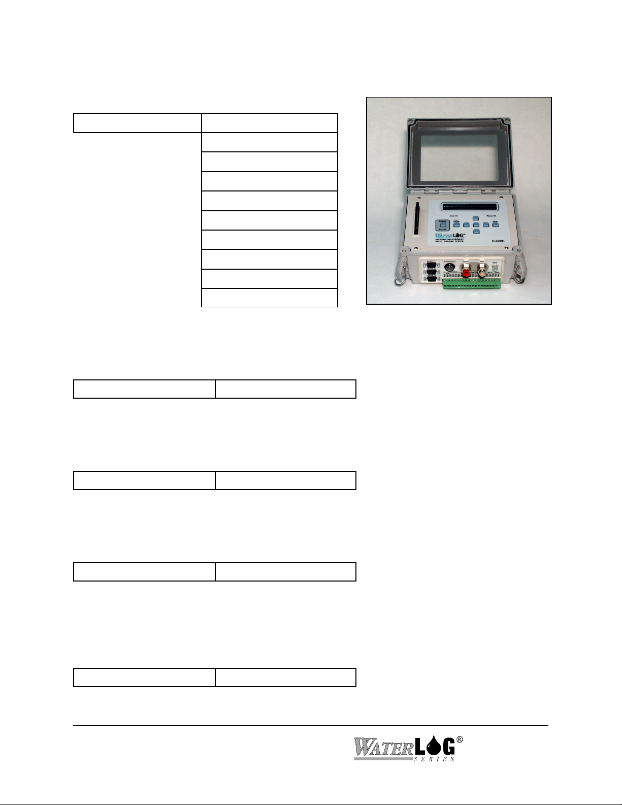
The photo below shows the input/output panel of the H-3551 where you make connections for power,
ground, communications, outlet to orifice, and pressure to your sensor. Observe the labels to determine
where you should make your connections.

2-2 Installation H-3551
2.2 Orifice and Sensor Connections
In its simplest form, a gas purge pressure measurement system consists of a gas source, a pressure
measurement device and an orifice tube all connected together in a “ T” arrangement. Because the H-3551
has the capability of purging the orifice line, a more complex connection is required. Do not use a simple
“T” connection to connect the bubbler and pressure sensor to the orifice line, instead, use the two
dedicated ports of the H-3551. The H-3551 includes an internal valve which isolates the pressure sensor
output from the orifice line during a purge sequence. This helps prevent a plugged orifice condition from
damaging the pressure sensor.
If you are using a pressure sensor other than the H-350XL you may need to take extra precautions to
further protect your pressure sensor. See Chapter3.
2.3 Recommended Field Installation Procedures
1. The H-355 must be wall mounted in the vertical position, with the manifold down. Mounting feet are
provided. A vertical mount helps ensure moisture will not accumulate in the internal pressure tank.
2. Connect the pressure line between the H-3551 and your pressure measurement device. This can be
done using the H-3551-Install kit. This kit is designed for use with the H-350XL. If your measurement
device has different connections, you will need to provide the appropriate fittings. You will need a 1/8"
NPT male tubing fitting for the sensor output. It is recommended that you use the 1/8" copper tubing
supplied in the install kit. The proper ferrules must be used to insure there are no leaks.
3. The H-3551 requires two separate power sources. First is the compressor 12V which powers the
compressor and control valves. This supply is typically made with heavy gauge wire to the gauge
station 12V battery. Second is the 12V which powers the control module. This source is supplied from
the pressure measurement sensor through the interface cable (provided), and into the control connector.
It is best to connect the compressor power first, then the control power second. If a pumping sequence
fails, the controller suspends pumping for a while to allow the battery to recharge. By connecting the
pump power first, the controller will not prematurely detect a dead battery and suspend pumping.
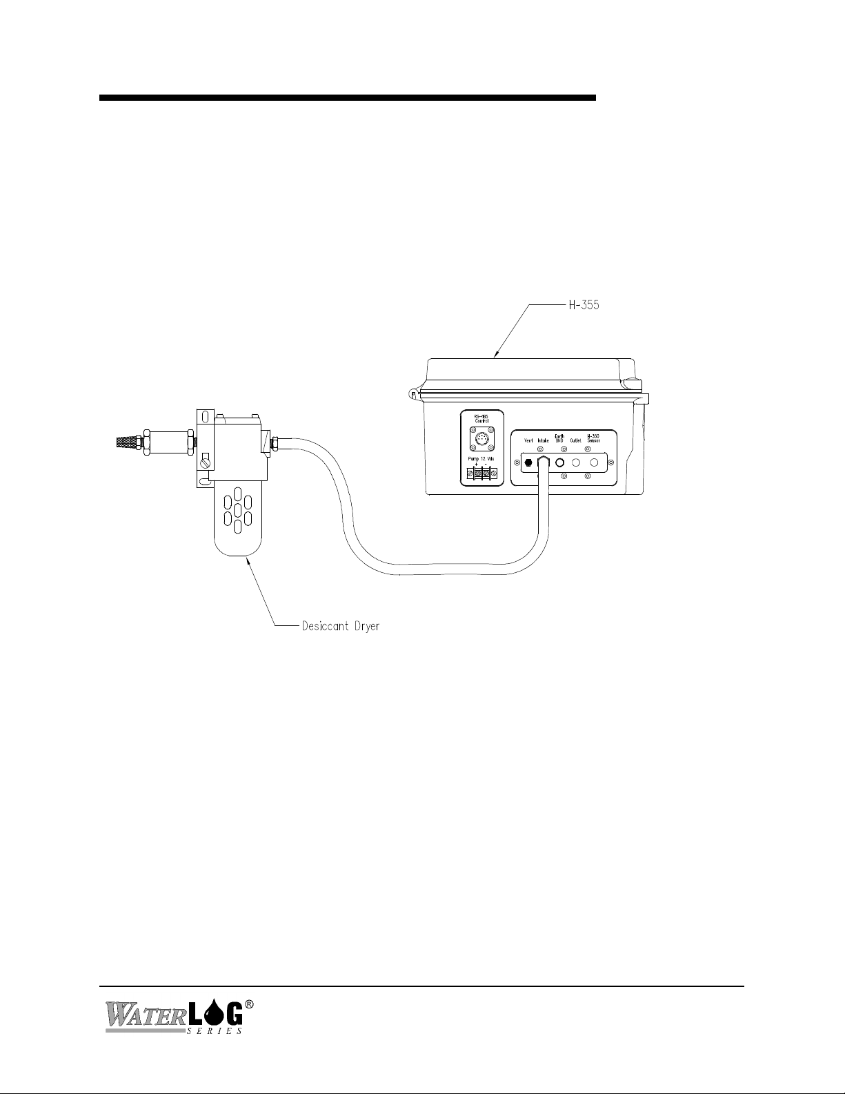
4. Generally, an external desiccator is required to dry the intake air. The desiccator prevents
accumulation of moisture in the tank, restriction and orifice line. Connect the output of the desiccator
to the port marked “intake”. Desiccators which employ “indicating” silica gel have the advantage of
visually showing the status of the desiccant. As the gel becomes saturated with moisture the gel turns
blue. See Appendix-B for further information and the specification for a recommended desiccator.

H-3551 Installation 2-3
H-355
H-350
Data Collection Platform/
Data Logger
Gas Purge Line Orifice
60 Bubbles
Per Minute
RS-485
Pressure Line to H-350
SDI-12 or RS-232
Figure 2-2. H-355/350 Pressure Measurement System
2.4 Control Connector
Pin No. Description Wire Color
1 RS485DAT+ Black
2 RS-485DAT- Brown
3 GND Red
4 GND Orange
5 +12V Yellow
6 +12V Green
7 +12V
8 SD-12 Data
9 Gnd
2.5 Connecting a WATERLOG® Series Model H-350XL Pressure Sensor
Figure 2-2 shows a typical installation of a complete pressure measurement system.
Control Connector &
Pump Power Terminals
2-4 Installation H-3551
Please note the following:
1. The install kit provided connects the “Sensor” output port of the bubbler directly to the
“Pressure Input” of the H-350XL without any additional parts.
2. The RS-485 serial cable provided is equipped with plugs on both ends for direct connection
between the “control” input of the H-3551 and the “Auxiliary output” of the H-350XL.
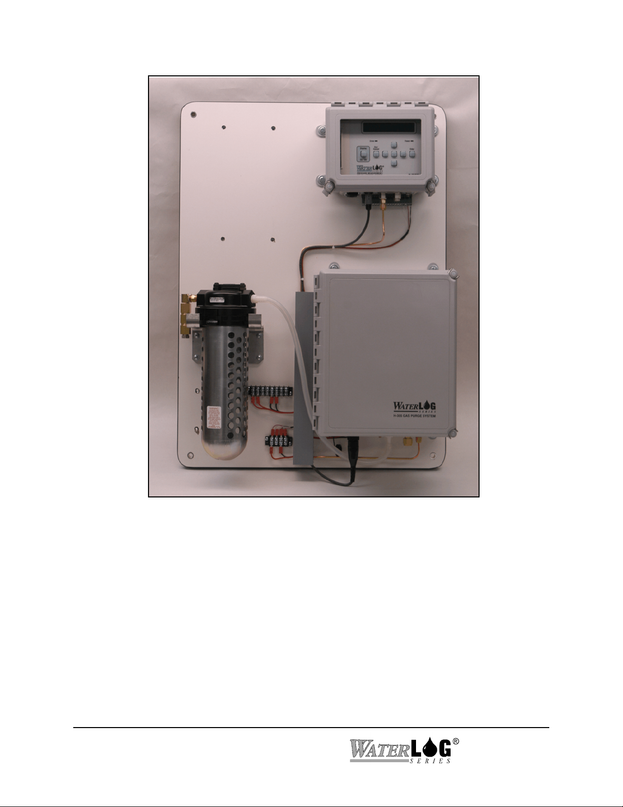
H-350XL pressure sensor and H-3551 bubbler
mounted on a plywood panel

Chapter 3
Operation
H-3551 Operation 3-1
3.1 Pumping Operation
During normal operation, if the tank pressure becomes too low the micro controller makes several
tests before turning the compressor on:
1. If the compressor power input (terminal strip) is below 10.0 volts, the compressor will not turn
on. This is to prevent further discharge of an already stressed battery.
2. The compressor will not turned on if a purge sequence within the previous elapsed 1-hour
failed. This allows the battery charger to charge the battery without the compressor draining
the battery as fast as it is charged.
Once the compressor is turned on, the battery voltage is no longer monitored by the micro
controller.
3.1.1 Maintenance Pressure Pump Failure
If the compressor runs longer than 60 seconds while pumping the tank to the pressure needed for
the desired bubble rate, the micro controller turns off the compressor and disables further pumping
for 30-seconds.
3.1.2 Purge Pump Failure
When a purge sequence is initiated, the compressor is activated to pump the tank to the specified
purge pressure. If the compressor runs longer than 300 seconds while pumping the tank to the
proper pressure, the micro controller turns off the compressor and disables all further pumping for
1-hour.
While servicing the system, these battery protection features can be inadvertently activated if the
12V pump power (via the terminal strip) is disconnected or fails while the compressor is running.
You can recover from these lockout conditions by momentarily disconnecting the RS-485 control
connector to reset the micro controller.
3-2 Operation H-3551
3.2 Operation with the H-350XL Pressure Sensor Attached
The following is a description of the H-350XL submenus used for configuring the bubbler.
<Gas Purge Setup > Auto Purge Enbl[OFF]
Bubble Rate[XXX]/min
Purge Thresh[XXX]PSI
Purge Presur[XXX]PSI
Purge Time: [XXX]sec
Manual Purge: ENT=Y
Timed Prg: [XX] days
Tank PSI = XX.X
Diff PSI = XX.XX
Last Prg=MM/DD HH:MM
The H-350XL can sense when the orifice line is restricted or plugged. The system can be
configured to do an automatic purge of the orifice line when it becomes necessary. This menu item
turns the auto purge on or off.
<Gas Purge Setup > Auto Purge Enbl[OFF]
This setting specifies the bubble rate that should flow from the end of the orifice tube. The
programmable range is 30 to 120 bubbles per minute.
<Gas Purge Setup > Bubble Rate[XXX]/min
This setting sets the purge threshold. If the orifice line pressure reaches the purge threshold, the
H-350XL can initiate an auto purge. The range of “Purge Thresh” is 10 to 65 psi.
<Gas Purge Setup > Purge Thresh[XXX]PSI
This setting is the pressure that the H-3551 uses to purge the orifice line. The range is 15 to 80 psi.
Set this value to a pressure which would reasonably purge sediment and debris from the orifice.
Keep in mind that the higher pressures require more energy from the battery.
<Gas Purge Setup > Purge Presur[XXX]PSI

H-3551 Operation 3-3
This setting is the duration of a purge in seconds. The range is 30 to 240 seconds. Allow enough
time for the purge to dissipate and the bubble rate to fall near zero.
<Gas Purge Setup > Purge Time: [XXX]sec
Pressing <Enter> on this item will initiate a purge sequence using the current purge settings.
<Gas Purge Setup > Manual Purge: ENT=Y
This option is used to force a purge every XX days. The limits are 00 to 99 days. If the option is set
to 00 then this option is in affect disabled. A value of 01 will cause a purge every day. The purge
will happen after the first scan past noon.
<Gas Purge Setup > Timed Prg: [XX] days
This value is the current pressure of the H-3551's internal air tank in psi. This value is informative
only and cannot be edited. The tank pressure should be approximately 3-5 PSI greater than the
orifice pressure.
<Gas Purge Setup > Tank PSI = XX.X
This value is the difference between the tank pressure and the pressure on the orifice line in psi.
Like tank psi, this value cannot be edited. This value is directly proportional to the bubble rate and
should be approximately 3-5 PSI.
<Gas Purge Setup > Diff PSI = XX.XX
This display shows the month, day any hour when the last purge sequence was made.
<Gas Purge Setup > Last Prg=MM/DD HH:MM

3-4 Operation H-3551
If the auto-purge feature of the H-350XL is enabled, the H-350XL is responsible for initiating
purges. Whenever the H-350XL makes a measurement, it compares the pressure data with the
“Purge Threshold” value. If the pressure is greater than the Purge Threshold, the H-350XL
commands the bubbler to initiate a purge sequence. During the purge, the H-350XL energizes its
internal auto-zero valve to isolate the H-350XL's precision sensor from the purge pressure. At the
completion of the purge, the H-350XL keeps its auto-zero valve energized for an additional 2.0
seconds. This is done to prevent damage to the H-350XL's precision sensor in case the orifice is
plugged and the orifice line momentarily holds the full purge pressure. A pressure relief valve in
the bubbler vents the over pressure to atmosphere during the 2 second delay.
After completion of a purge sequence, the H-350XL makes another pressure measurement. If the
pressure is still greater than the Purge Threshold value, the H-350XL knows the purge failed. It
then activates a timer which disables further purges for the next 24 hours. This is done to prevent a
plugged orifice form causing continuous purges which would quickly drain the battery.
3.3 Stand-Alone Operation
The H-3551 gas purge system can be used “stand-alone” with pressure measurement devices other
than the H-350XL. You do lose some flexibility in that you cannot edit the bubbler settings in the
field and the purge feature cannot be coordinated with a pressure measurement such that pressure
measurements are not made during a purge.
When operating stand-alone, the factory preset values are:
Bubble Rate: 60 Bub/min
Pressure to Purge With: 40 PSI
Pressure to Initiate a Purge: 20 PSI
Purge Time: 45 sec
These settings can also be monitored or edited via the SDI-12 port built into the H-3551. The H3551 functions as a SDI-12 “sensor”. When connected to a SDI-12 host such as a data logger or
H-4191 RS-232 side-kick interface you can issue extended SDI-12 commands to read or write
these settings. If the data logger issues and “aM!” command, the H-3551 initiates a purge
sequence. See Chapter 5 for further details.
If needed, these settings can be configured at the factory. The factory must be notified of desired
settings prior to shipment.

H-3551 Operation 3-5
WARNING: THERE IS A DISTINCT POSSIBILITY OF DESTROYING YOUR
PRESSURE SENSOR. THIS CAN BE AVOIDED BY INSTALLING
AN ISOLATION VALVE BETWEEN THE H-3551 AND YOUR
SENSOR.
If a purge does not clear a plugged orifice line, the purge pressure will be applied to the sensor
output of the H-3551. The H-350XL has an internal valve which protects its precision pressure
transducer from a failed purge. When operating the H-3551 with a sensor other than the H-350XL,
the purge pressure could be applied to your sensor before the H-3551's internal pressure relief valve
can pop. It is your responsibility to verify that your sensor can handle the purge pressure, or install
an isolation valve between the H-3551 and your sensor. The valve must be closed prior to a purge
and remain closed until the purge is completed, or until the tank pressure falls below your sensor’s
maximum pressure rating.
3.4 Manual Purge
The H-3551 has an internal button which allows a manual purge to be initiated. This feature allows
you to clear a plugged orifice or verify the orifice is clear.
The Purge button is located inside the H-3551 enclosure, on the top corner of the control module.
Pressing this for one to two seconds initiates a purge sequence. The compressor will be turned on
and the tank pressure raised to the “Purge Pressure”. During this time, the bubble rate will rise
proportionally with the pressure. Next, the compressor is turned off and the purge valve is
actuated to dump the tank pressure directly to the orifice line. While the purge valve is actuated
the pressure sensor output is blocked by a valve to prevent the purge pressure from damaging the
pressure measurement system. During the purge, the orifice should produce vigorous bubbling with
the bubble rate falling eventually to zero. After a delay equal to the “Purge Delay”, the purge valve
is closed and the compressor is again turned on to restore the bubble rate to its normal value.
Note: When the button is pressed, if the tank pressure is already higher than the “Purge Pressure”
the purge sequence will not be initiated.

3-6 Operation H-3551

Chapter 4
Maintenance/Trouble Shooting
H-3551 Maintenance 4-1
4.1 Maintenance
Sustained operation of the H-3551 is almost maintenance-free. Because the compressor only runs
for a few seconds every hour, it will last for many years. The H-3551 includes safety provisions
that will not allow the compressor to run continuously for long periods of time. This protects the
pump and other components in case of a plugged orifice or other malfunction.
Periodically check your gauge station battery to ensure it is in good condition for pumping together
with any other equipment that you have installed in the gauge station.
From time to time check the inlet line filter (located between the manifold and the suction side of
the pump) for any blockage or restriction. If blockage or restriction is present, the filter must be
replaced.
All fittings must be secure. At 60 bubbles/minute, even a tiny leak will allow the entire gas flow to
escape.
4.2 Trouble Shooting
It is unlikely that this manual will ever contain trouble shooting tips to cover every problem that
will be encountered. Feedback from customers is very valuable and greatly aids in the quest for
constant product enhancement. Please feel free to call the factory for technical assistance and also
with solutions you have found to past problems.
The following list of problems and possible solutions.
H-350 reports “H-355 NOT RESPONDING”
! Verify the power connections to the H-3551. Reinitialize the internal controller by momentarily
unplugging the RS-485 control cable connector.
! Check all connections including Power, Gnd and the RS-485 communication connector. +12V
power must be supplied via both the compressor power terminals and the RS-485 connector
(from the data logger).
Intermittent Operation
! Check your power and ground connections. Moisture over time can oxidize and corrode the
battery terminals, connectors and pins.
! Measure the power supply/battery voltage at the input terminal strip while the pump is running.
! The H-3551 has several safety features which may suspend pumping in order to preserve a dead
battery. Refer to Chapter 2

4-2 Maintenance H-3551
4.3 Bubble Test
When visiting a gauge station it is recommended to always take a bucket and a length of rubber
tubing. With the rubber tubing you can disconnect the station’s orifice line and direct the gas flow
into a bucket of water. This fast and productive test allows you to check for proper bubbling, leaks
and other problems. Realize however, if the H-3551 was bubbling into deep water, when you
direct the gas flow to a shallow bucket the bubble rate will be abnormally high for 5-10 minutes
until the H-3551 can adjust to the new water depth.
It is also recommended to have dish detergent, a small paintbrush or “snoop” in your toolbox for
testing for air leaks. Again, at 60 bubbles/minute, even a tiny leak will allow the entire gas flow to
escape to the atmosphere.

Chapter 5
SDI-12 Command and Response Protocol
H-3551 SDI-12 Command and Response Protocol 5-1
5.0 SDI-12 Command and Response Protocol
This is a brief description of the Serial Digital Interface (SDI-12) Command and Response Protocol
used by the WATERLOG® Series Model H-3551 bubbler. Included is a description of the
commands and data format supported by the H-3551.
Refer to the document "A SERIAL DIGITAL INTERFACE STANDARD FOR HYDROLOGIC
AND ENVIRONMENTAL SENSORS.” Version 1.2 April 12, 1996 Coordinated by the SDI-12
Support Group, 135 East Center, Logan, Utah.
During normal communication, the data recorder sends an address together with a command to the
H-4161 SDI-12 interface. The H-4161 then replies with a "response." In the following
descriptions, SDI-12 commands and responses are enclosed in quotes. The SDI-12 address and the
command/response terminators are defined as follows:
"a" Is the sensor address. The following ASCII Characters are valid addresses:
"0-9", "A-Z", "a-z", "*", "?". Sensors will be initially programmed at the
factory with the address of "0" for use in single sensor systems. Addresses
"1 to 9" and "A to Z" or "a to z" can be used for additional sensors
connected to the same SDI-12 bus. Address "*" and "?" are "wild card"
addresses which select any sensor, regardless of its actual address.
"!" Is the last character of a command block.
"<cr><lf>" Are carriage return (0D) hex and line feed (0A) hex characters. They are the
last two characters of a response block.
Notes:
• All commands/responses are upper-case printable ASCII characters.
• Commands must be terminated with a "!" character.
• Responses are terminated with <cr><lf> characters.
• The command string must be transmitted in a contiguous block with no gaps of more
than 1.66 milliseconds between characters.

5-2 SDI-12 Command and Response Protocol H-3551
5.1 Command Summary
The H-3551 supports the following SDI-12 commands:
Standard Commands:
aM! Initiate purge
aM1! Initiate measurement
aM2! Initiate special measurement
aD0! Send data
aV! Verify
aI! Send identification
a! Send acknowledge
aAn! Change address
Extended Commands:
aXRBR! Read bubble rate
aXWBRnn! Write bubble rate
aXRPP! Read purge pressure
aXWPPnn! Write purge pressure
aXRPT! Read purge time
aXWPTnn! Write purge time
aXTPM! Test pump motor
aXTPV! Test purge valve
aXTAZ! Test auto-zero valve
aXCOP! Test the COP timer
aXTEST! Display the current settings
aXHELP! Display the supported commands

H-3551 SDI-12 Command and Response Protocol 5-3
5.2 Measure Command
The H-3351 supports three measure commands. Data values generated in response to these
commands are stored in the sensor's buffer for subsequent collection using "D" commands. The
data will be retained in the sensor until another "M", " C", or "V" command is executed.
Command
Response Description
"aM!" "atttn<cr><lf>" Initiate measurement
Where:
a is the sensor address ("0-9", "A-Z", "a-z", "*", "?").
M is an upper-case ASCII character
ttt is a three digit integer (000-999) specifying the maximum time, in seconds, the
sensor will take to complete the command and have measurement data available in
its buffer.
n is a single digit integer (0-9) specifying the number of values that will be
placed in the data buffer. If "n" is zero (0), no data will be available using
subsequent "D" commands.
Upon completion of the measurement, a service request "a<cr><lf>" may be sent to the data
recorder indicating the sensor data is ready. The data recorder may wake the sensor with a break
and collect the data any time after the service request is received or the specified processing time
has elapsed.
The aM! causes the H-3351 to initiate a purge sequence. Upon completion of the purge the H3551 places a success/fail response parameter in the sensor buffer and sends a service request..
Example of a H-3551 "aM!" command:
Command Response Time Values Description
"aM!" "a2721<cr><lf>" 272 sec 1 Initiate a purge
Subsequent Command
Response Description
"aD0" a+0<cr><lf> Purge failed (low battery voltage)
"aD0" a+1<cr><lf> Purge succeeded

5-4 SDI-12 Command and Response Protocol H-3551
The aM1! causes the H-3351 to initiate a measurement . This command takes less than 3 seconds
to complete and places 5 parameters in the sensor buffer.
Example of a H-3551 "aM1!" command:
Command Response Time Values Description
"aM1!" "a0035<cr><lf>" 3 sec 5 Initiate a measurement
Subsequent Command
Response
"aD0" a+AA.AAA+BB.BBB+CC.CCC+DD.DD+EE.EE<cr><lf>
where: AA.AAA = Tank pressure (PSI)
BB.BBB = Line pressure (PSI)
CC.CCC = Sensor temperature (°C)
DD.DD = System battery voltage (volts)
EE.EE = Pump battery voltage (volts)
The aM2! causes the H-3351 to initiate a measurement . This command takes less than 3 seconds
to complete and places 8 parameters in the sensor buffer. This command is normally used only for
calibration and test during manufacturing.
Example of a H-3551 "aM2!" command:
Command Response Time Values Description
"aM2!" "a0038<cr><lf>" 3 sec 8 Initiate a measurement
Subsequent Command
Response
"aD0" a+AA.AA+BB.BB+CCCC+DDDD+EE.EE+FF.FF+GGGG+HHHH<cr><lf>
where: AA.AA = Tank pressure (PSI)
BB.BB = Tank temperature (°C)
CCCCC = Tank pressure (raw A/D counts)
DDDDD = Tank temperature (raw A/D counts)
EE.EE = Line pressure (PSI)
FF.FF = Line temperature (°C)
GGGGG = Line pressure (raw A/D counts)
HHHHH = Line temperature (raw A/D counts)

H-3551 SDI-12 Command and Response Protocol 5-5
5.3 Concurrent Measurement Command
This is a new command for the Version 1.2 SDI-12 Specification. A concurrent measurement is
one which occurs while other SDI-12 sensors on the bus are also taking measurements. This
command is similar to the “aM!” command, however, the nn field has an extra digit and the sensor
does not issue a service request when it has completed the measurement. Communicating with
other sensors will NOT abort a concurrent measurement. Data values generated in response to
this command are stored in the sensor's buffer for subsequent collection using "D" commands. The
data will be retained in the sensor until another "M", "C", or "V" command is executed.
Command
Response Description
"aC!" "atttnn<cr><lf>" Initiate measurement
Where:
a is the sensor address ("0-9", "A-Z", "a-z", "*", "?").
C is an upper-case ASCII character
ttt is a three digit integer (000-999) specifying the maximum time, in seconds, the
sensor will take to complete the command and have measurement data available in
its buffer.
nn is a two digit integer (00-99) specifying the number of values that will be
placed in the data buffer. If "n" is zero (0), no data will be available using
subsequent "D" commands.
The data recorder may wake the sensor with a break and collect the data anytime after the
specified processing time has elapsed.

5-6 SDI-12 Command and Response Protocol H-3551
5.4 Send Data Command
The Send Data command returns sensor data generated as the result of previous "aM!", "aM1!",
"aM2!", "aC!", "aC1!", "aC2!" or "aV!" commands. Values returned will be sent in 33 characters
or less. The sensor's data buffer will not be altered by this command.
Command
Response
"aD0!" "apd.d<cr><lf>"
Where:
a is the sensor address ("0-9", "A-Z", "a-z", "*", "?").
D0 are upper-case ASCII characters.
p Is a polarity sign (+ or -)
d.d represents numeric digits before and/or after the decimal. A decimal may be used in
any position in the value after the polarity sign. If a decimal is not used, it will be
assumed to be after the last digit.
For example: +3.29 +23.5 -25.45 +300
If the "aD0!" returns no data (“a<cr><lf>” only), it means that no measurement data is available
(or the measurement was aborted) and a new "M" command must be sent.
Example of a H-3551 "aD0!" command:
Previous Command
Response
"aM!" "a2721<cr><lf>"
Subsequent Command Response Description
"aD0" a+0<cr><lf> Purge failed (low battery)
"aD0" a+1<cr><lf> Purge succeeded
H-3551 SDI-12 Command and Response Protocol 5-7
5.5 Send Acknowledge Command
The Send Acknowledge Command returns a simple status response which includes the address of the sensor.
Any measurement data in the sensor's buffer is not disturbed.
Command
Response
"a!" "a<cr><lf>"
Where: a Is the sensor address ("0-9", "A-Z", "a-z", "*", "?").
3.6 Initiate Verify Command
The Verify Command causes a verify sequence to be performed. The result of this command is similar to
the "aM!" command except that the values generated are fixed test data and the results of diagnostic
checksum tests. The data generated in response to this command is placed in the sensor's buffer for
subsequent collection using "D" commands. The data will be retained in the sensor until another "M", "C",
or "V" command is executed.
Command
Response Description
"aV!" "atttn<cr><lf>" Initiate verify sequence
Where:
a is the sensor address ("0-9", "A-Z", "a-z", "*", "?").
V is an upper-case ASCII character.
ttt is a three digit integer (000-999) specifying the maximum time, in seconds, the sensor will
take to complete the command and have data available in its buffer.
n is a single digit integer (0-9) specifying the number of values that will be
placed in the data buffer. If "n" is zero (0), no data will be available using
subsequent "D" commands
Example of a "aV!" command:
Command
Response Time Values Description
"aV!" "a0014<cr><lf>" 1 sec 4 Return fixed data and diagnostic data for testing
purposes.
Subsequent Command Response
"aD0" a+123.456+78.9+x+y<cr><lf>
Key
Description Units
+123.456 Fixed test data
+78.9 Fixed test data
x Memory checksum 0-65535
y Checksum test “0” = Failed, “1” = Passed

5-8 SDI-12 Command and Response Protocol H-3551
5.7 Send Identification Command
The Send Identification Command responds with sensor vendor, model, and version data. Any
measurement data in the sensor's buffer is not disturbed.
Command Response
"aI!" "allccccccccmmmmmmvvvxx...xx<cr><lf>"
Where:
a is the sensor address ("0-9", "A-Z", "a-z", "*", "?").
I is an upper-case ASCII character.
ll is the SDI-12 version compatibility level, e.g. version 1.2 is represented as
"12".
cccccccc is an 8 character vendor identification to be specified by the vendor and
usually in the form of a company name or its abbreviation.
mmmmmm is a 6 character field specifying the sensor model number.
vvv is a 3 character field specifying the sensor version number.
xx...xx is an optional field of up to a maximum of 13 characters to be used for
serial number or other specific sensor information not relevant to operation
of the data recorder.
Example of a "aI!" command:
"a12 DAA H-3551vvvS#nnnnnnVkkk<cr><lf>"
H-3551 implementation of the optional 13 character field:
S#nnnnnnVkkk (12 bytes total)
Where:
"nnnnnn is a six character sensor serial number
"kkk" is a three digit sensor firmware revision level
H-3551 SDI-12 Command and Response Protocol 5-9
5.8 Change Sensor Address Command
The Change Sensor Address Command allows the sensor address to be changed. The address is
stored in non-volatile Flash memory within the sensor. The H-3551 will not respond if the
command was invalid, the address was out of range, or the Flash programming operation failed.
Command
Response Description
"aAn! "n<cr><lf>" Change sensor address
Where:
a is the current (old) sensor address ("0-9", "A-Z", "a-z", "*", "?"). An ASCII "*"
may be used as a "wild card" address if the current address is unknown and only
one sensor is connected to the bus.
A is an upper-case ASCII character.
n is the new sensor address to be programmed ("0-9", "A-Z").
NOTE: To verify the new address use the "Identify Command."
Example of a "Change Sensor Address" command:
Command
Response Description
"aA2!" "2<cr><lf>" Change sensor address to "2"

5-10 SDI-12 Command and Response Protocol H-3551
5.9 Extended Read/Write BubbleRate, PurgePressure and PurgeTime
These commands allow the user to read or write several bubbler configuration settings. The
settings are stored in non-volatile Flash memory. Once the new value is written to the Flash
memory, a copy is sent to the sensor data buffer for verification. This data can be viewed by
using a subsequent "D" command. To verify these settings any other time, use the respective read
commands. These commands take 1 second to complete and place 1 value in the data buffer. The
H-3551 will only accept settings within a specific range as listed below.
Command Response Description
"aXRBR!" “a0011<cr><lf>" Read bubble rate setting (bub/min)
"aXRPP!" “a0011<cr><lf>" Read purge pressure setting (psi)
"aXRPT!" “a0011<cr><lf>" Read purge time setting (seconds)
"aXWBRdd!" “a0011<cr><lf>" Write bubble rate setting (bub/min)
"aXWPPdd!" “a0011<cr><lf>" Write purge pressure setting (psi)
"aXWPTdd!" “a0011<cr><lf>" Write purge time setting (seconds)
Where: a is the sensor address ("0-9", "A-Z", "a-z", "*", "?").
XRBR are upper case characters.
XRPP are upper case characters.
XRPT are upper case characters.
XWBR are upper case characters.
XWPP are upper case characters.
XWPT are upper case characters.
ddd is the new value (For example: 20.0, 195)
Max/min Settings
Parameter Min Max Units
Bubble Rate 30 120 bubbles/min
Purge Pressure 15 80 psi
Purge Time 30 240 seconds
Example of a H-3351 Extended Read Bubble Rate command:
Command Response Time Values Description
"aXRBR!" "a0011<cr><lf>" 1 sec 1 Read BubbleRate
Command
Response Description
"aD0!" "a+50.0<cr><lf>" BubbleRate is 50 bubbles/min
Example of a H-3351 Extended Write Bubble Rate command:
Command Response Time Values Description
"aXWBR30.0!" "a0011<cr><lf>" 1 sec 1 Write BubbleRate
Command
Response Description
H-3551 SDI-12 Command and Response Protocol 5-11
"aD0!" "a+30.0<cr><lf>” BubbleRate is 30.0 bubbles/min
5.10 Extended Test Pump Motor Command
This command is used during installation and testing to activate the pump motor for 5.0 seconds.
Example of a H-3551 Extended "Test Pump Motor" command:
Command
Response Description
"aXTPM!" "0050<cr><lf>" Activate the pump motor for 5 seconds
5.11 Extended Test Purge Valve Command
This command is used during installation and testing to activate the purge valve solenoid for 5.0
seconds.
Example of a H-3551 Extended "Test Purge Valve" command:
Command
Response Description
"aXTPV!" "0050<cr><lf>" Activate the purge valve for 5 seconds
5.12 Extended Test Auto-Zero Valve Command
This command is used during installation and testing to activate the auto-zero valve solenoid for
5.0 seconds.
Example of a H-3551 Extended "Test Auto-Zero Valve" command:
Command
Response Description
"aXTAZ!" "0050<cr><lf>" Activate the auto-zero valve for 5 seconds
5.13 Extended Test COP (Computer Operating Properly) Timer Command
This command causes the COP timer to expire which in turn should initiate a system reset.
Example of a H-3551 Extended "Test COP Timer" command:
Command
Response Description
"aXCOPT!" "0050<cr><lf>" Test the COP timer

5-12 SDI-12 Command and Response Protocol H-3551
5.14 Extended “XTEST” Command
This command is used for installation and testing and requires the use of a H-4191 Sidekick
interface and a PC. This command causes the H-3551 to display a listing of the H-3551's current
settings, followed by a repeating printout of real-time measurement data. This is not compliant
with the SDI-12 specification and is not used with data loggers.
An example of an “XTEST” printout is shown below:
H-3551 Settings:
Firmware Checksum = PASS
Bubbler Mode = Remote Host
Bubble Rate (bub/s) = 60
Hysteresis (psi) = 0.50
Purge Pressure (psi) = 40.00
Purge Threshold (psi)= 20.00
Purge Time (sec) = 45
AZ Interval (min) = 30
Tank_PSI=xx.xxx, Tank_TEMP=xx.xx, Tank_Vp=xxxxx, Tank_Vt=xxxxx
Line_PSI=xx.xxx, Line_TEMP=xx.xx, Line_Vp=xxxxx, Line_Vt=xxxxx
Tank_PSI=xx.xxx, Tank_TEMP=xx.xx, Tank_Vp=xxxxx, Tank_Vt=xxxxx
Line_PSI=xx.xxx, Line_TEMP=xx.xx, Line_Vp=xxxxx, Line_Vt=xxxxx
Tank_PSI=xx.xxx, Tank_TEMP=xx.xx, Tank_Vp=xxxxx, Tank_Vt=xxxxx
Line_PSI=xx.xxx, Line_TEMP=xx.xx, Line_Vp=xxxxx, Line_Vt=xxxxx
etc.

H-3551 SDI-12 Command and Response Protocol 5-13
5.15 Extended “XHELP” Command
This command is used for installation and testing and requires the use of a H-4191 Sidekick
interface and a PC. This command causes the H-3551 to display a listing of the supported SDI-12
commands. This is not compliant with the SDI-12 specification and is not used with data loggers.
An example of the “XHELP” printout is shown below:
H-3551 SDI-12 Commands:
M Initiate Purge (aM!)
M1 Make measurement (aM1!)
(TankPSI:LinePSI:Temperature:SysBat:PumpBat)
M2 Make measurement (aM2!)
(TankPSI:TankTemp:TankVp:TankVt:LinePSI:LineTemp:LineVp:LineVt)
D Send Data (aD0!)
V Verify (aV!)
I Send Identification (aI!)
! Send Acknowledge (a!)
An Change Address (aAn!)
Extended Commands:
XRBR Read bubble rate
XWBRnn Write bubble rate
XRPP Read purge pressure
XWPPnn Write purge pressure
XRPT Read purge time
XWPTnn Write purge time
XTPM Test pump motor
XTPV Test purge valve
XTZV Test auto-zero valve
XCOPT Test COP timer
XTEST Make repeating measurements
XHELP Print this listing

5-14 SDI-12 Command and Response Protocol H-3551

Appendix A
Specifications
H-3551 Specifications A-1
Environmental
Standard Operating Range: -40° to 60° C
Storage: -50° to 80° C
It is recommended the H-3551 be installed in a weather
shielded enclosure (gauge station).
Gas Delivery
Control System: Microprocessor controlled
Technology: Constant mass flow
Gas Flow Control: Bubble rate is user selectable from
30 to 120 bubbles per minute.
Built-in auto zero compensation
No needle valve
(patent application in process)
Compressor
Type: HI-REL medical grade ISO 9003
qualified piston compressor
(avoids broken diaphragm problems)
Serviced for extended temperature
operation
Operation: Low duty cycle
5 hours typical runtime per year at 60
bubbles per minute
Pumping Time: 1-second (average)
Purge Functions
Purge Pressure: User Selectable 15 PSI to 80 PSI
Options: 1. Manual
2. Internally sensed
3. Automatic timed interval
4. Remote controlled
Control Interface
Type: RS-485
Protocol: ASCII
Baud Rate: 9600 bps, half-duplex, 8 bit, no parity,
1 stop bit
Power
Qualified for operation with a 12-volt battery
Two supply inputs:
1. Electronics supply via the RS-485 cable
2. Compressor supply
Voltage 10 to 16 volts
Current: 15 milliamperes average (@ 60 bub/min)
Max Current: 3.0A (pump running)
Physical
Enclosure: Corrosion resistant, Type 4X
Molded fiberglass
Hinged cover
Seamless foam-in-place gasket
Size: 10.5 in. wide x 12.5 in. long x 6.0
in. deep
Weight: 12 pounds
Mounting: Hardware supplied for wall
mounting
Pressure Outlet: 1/8 in. FNPT
Sensor Pressure Outlet: 1/8 in. FNPT
Air Intake: 1/8 in. FNPT
Pressure relief valve: Internal
Ordering Information
H3551 Base model
H3551/000 Standard H355 "Smart-gas" system
H3551/350 Combination H3551 "Smart-gas" system and H350
pressure measurement system
Warranty
The WATERLOG® H-3551 is warranted against defects in
materials and workmanship for one year from date of shipment.
Notes
Specifications subject to change without prior notice due to
ongoing commitment to product testing and improvement.

5-2 SDI-12 Command and Response Protocol H-3551
Appendix B
Dry Air System
H-3551 Dry Air System B-1
Figure B-1 shows the connections for a typical H-3551 dry air system.
The following is the installation and maintenance documentation for a recommended desiccant
dryer.

B-2 Dry Air System H-3551
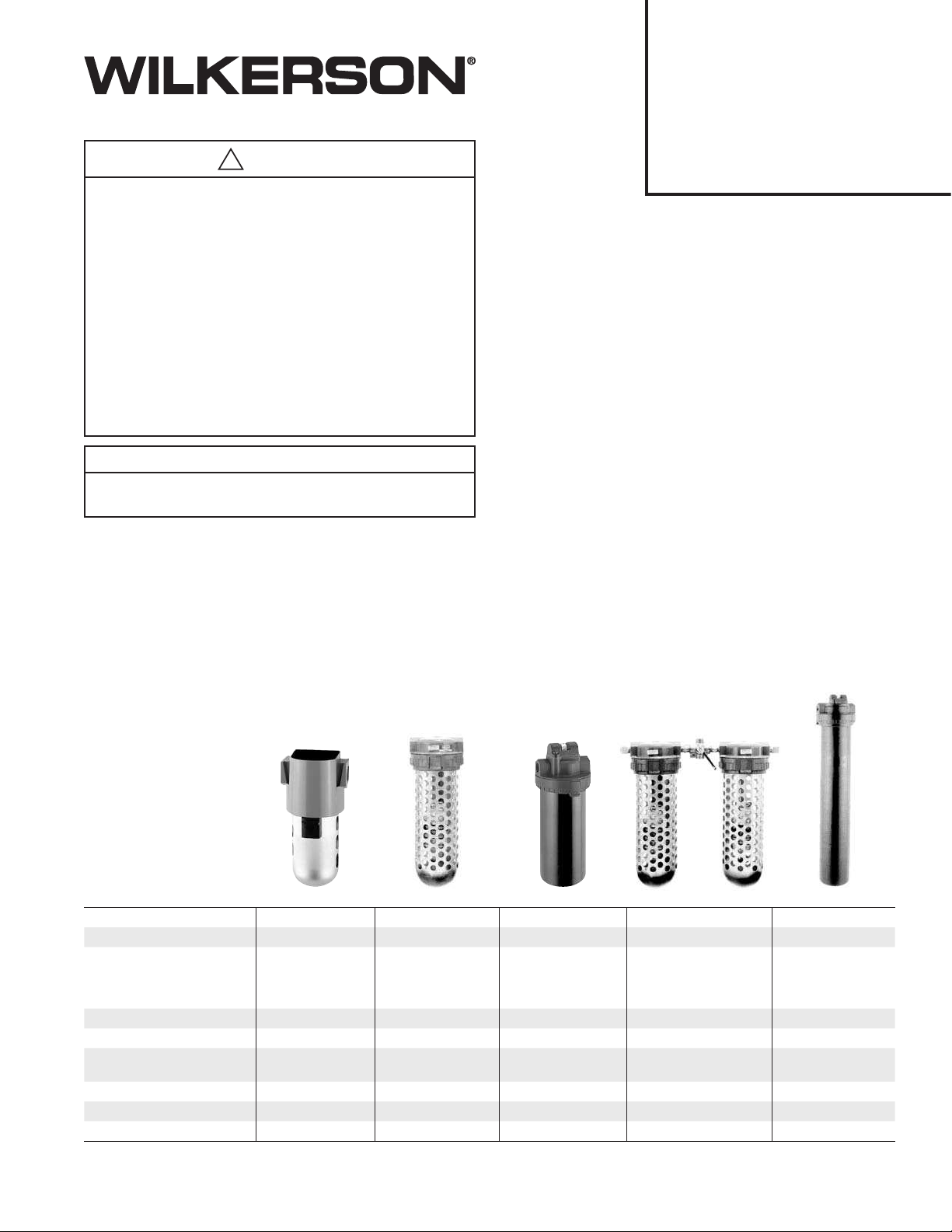
Description
Wilkerson Manual Dryers are intended to remove water vapor from the
compressed air system. Atmospheric dew points as low as -100°F (73°C) are achievable when operated within rated unit specifications.
General Safety Information
•
Release all air pressure from intended airline before installation.
• Install unit in air line before opening desiccant container. After unit
installation, add desiccant following steps in desiccant replacement
instructions on page 2.
• Always make sure bowl, bowl guard, and clamp ring are in place
and the clamp ring is securely locked before pressurization.
• DO NOT exceed the pressure and temperature ratings as shown in
the specifications.
• Follow all local, state and
federal EPA, OSHA, and
similar codes regarding
disposal of old desiccant.
Installation
1. Refer to WARNING (on page 6).
2.
Install as close as possible to the point where the air is being used.
3.
Install unit with the airflow going in the direction of the arrow. For the
X04, install with airflow entering at the bottom center port of the 4-way
valve and exiting at the center port of the shuttle valve.
4. Install unit on air line before opening desiccant container. After
installation, add desiccant. Shake and tap bowl while filling to settle
desiccant. Fill Model X25 and X03/X04 to 1/8" below inner shoulder
of bowl. Fill Model X06 bowl to within 1/2" of top.
5. Replace bowl and bowl guard, or metal bowl, and clamp ring onto
the unit. Be sure clamp ring is securely locked in place before
pressurizing unit.
6.
Most manual desiccant dryer users will achieve optimal results when
installing the dryer as close to the equipment or process being protected
as possible in the compressed air system. Most users, especially those
with high quality air requirements, should protect their system and the
manual dryer with one or more of the following types of components:
Please see page 4 for exact model recommendations.
•
Liquid Separator: Should be used prior to the manual desiccant
dryer in any system where large slugs of liquid water are anticipated.
The manual desiccant dryer silica gel or mole sieve can be destroyed
by large amounts of liquid moisture. Most systems which have an
aftercooler and separator, and/or a refrigerated air dryer, will not
require a liquid separator. An alternative is to use a particulate filter/
separator, described below.
• Particulate Filter/Separator: Should be used prior to the manual
desiccant dryer in any system where significant amounts of dirt,
pipe scale, etc, and/or liquid water, is present, in order to prevent
clogging the manual dryer or harming the desiccant. A particulate
filter/separator should be used prior to a coalescing filter to extend
the life of the coalescing element.
Specifications X06 X03 Plastic Bowl X03 Metal Bowl X04 X25 Metal Bowl
Maximum Pressure 150 psig (10.3 bar) 150 psig (10.3 bar) 150 psig (10.3 bar) 150 psig (10.3 bar) 150 psig (10.3 bar)
Maximum Temperature 125°F (52°C) 125°F (52°C) 150°F (66°C) 125°F (52°C) 150°F (66°C)
Atmospheric Dewpoint*
000 Model: Silica Gel
U00 Model: 4A Molecular
Sieve
000 Model:
-45°F (-43°C)
U00 Model:
-100°F (-73°C)
000 Model:
-45°F (-43°C)
U00 Model:
-100°F (-73°C)
M00 Model:
-45°F (-43°C)
MU0 Model:
-100°F (-73°C)
000 Model:
-45°F (-43°C)
U00 Model:
-100°F (-73°C)
000 Model:
-45°F (-43°C)
U00 Model:
-100°F (-73°C)
Maximum Continuous Airflow* 5 scfm (2.3 dm
3
/s) 10 scfm (4,7 dm3/s) 10 scfm (4.7 dm3/s) 10 scfm (4.7 dm3/s) 25 scfm (11.8 dm3/s)
Total Airflow* 600 scf (283 dm
3
) 4400 scf (2076 dm3) 4400 scf (2076 dm3) 4400x2 scf (2076x2 dm3) 11,000 scf (5191 dm3)
Total Min. of Operation @
Max Continuous Airflow
120 min. 440 min. 440 min. 880 min. 440 min.
Unit Weight With Desiccant 1.13 lbs. (0.51 kg) 7.4 lbs. (3.4 kg) 6.8 lbs. (3.1 kg) 15.0 lbs. (6.8 kg) 11.2 lbs. (5.1 kg)
# of Desiccant Bags/Charge 1 Bag ** 2 Bags *** 2 Bags*** 4 Bags*** 5 Bags***
Pipe Connections 1/4" NPT (BSPP) 1/4", 1/2" NPT (BSPP) 1/4", 1/2" NPT (BSPP) 1/4", 1/2" NPT (BSPP) 1/2" NPT (BSPP)
*With Dry Desiccant at 100 psig (7 bar) and 70°F (21°C)
** Each bag weighs .25 lbs. (.11kg)
*** Each bag weighs .88 lbs. (.40kg)
Installation & Service Instructions
83-050-000
Manual Desiccant Dryer Models
X06, X03, X04, and X25 with
Variations and Accessories
ISSUED: April, 2007
Supersedes: October, 2004
Doc. #83050000, EN #070216, Rev. 3
!
WARNING
To avoid unpredictable system behavior that can cause personal injury
and property damage:
• Disconnect electrical supply (when necessary) before installation,
servicing, or conversion.
• Disconnect air supply and depressurize all air lines connected to this
product before installation, servicing, or conversion.
• Operate within the manufacturer’s specified pressure, temperature,
and other conditions listed in these instructions.
• Medium must be moisture-free if ambient temperature is below
freezing.
• Service according to procedures listed in these instructions.
• Installation, service, and conversion of these products must be
performed by knowledgeable personnel who understand how
pneumatic products are to be applied.
• After installation, servicing, or conversion, air and electrical supplies
(when necessary) should be connected and the product tested for
proper function and leakage. If audible leakage is present, or the
product does not operate properly, do not put into use.
• Warnings and specifications on the product should not be covered by
paint, etc. If masking is not possible, contact your local representative
for replacement labels.
Safety Guide
For more complete information on recommended application guidelines, see the
Safety Guide section of Pneumatic Division catalogs or you can download the
Pneumatic Division Safety Guide at: www.wilkersoncorp.com
Richland, MI 49083 Tel: (269) 629-5000
2
d. See replacement parts list for specifics on kit numbers for
replacement desiccant.
3. Desiccant regeneration:
a. —For silica gel (“000”) units: Pour out used Pink desiccant
onto flat pan. Place Pink desiccant in 350°F (176°C) oven for
approximately three hours or until the desiccant color has
changed back to Blue.
—For 13x molecular sieve (“X00”) units cannot be
regenerated. See page 5 for replacement kits.
—For 4A molecular sieve (“U00”) units: Pour out used
desiccant onto flat pan. Place desiccant in 600°F (316°C)
oven for up to a maximum of 3 hours.
b. Remove desiccant from oven and allow to cool down to ambient
temperature.
c. Pour desiccant back into unit bowl, periodically shaking and
tapping to settle the desiccant.
4. Replace bowl and bowl guard, or metal bowl, and clamp ring onto
the unit. Be sure clamp ring is securely locked in place before
repressurizing the unit.
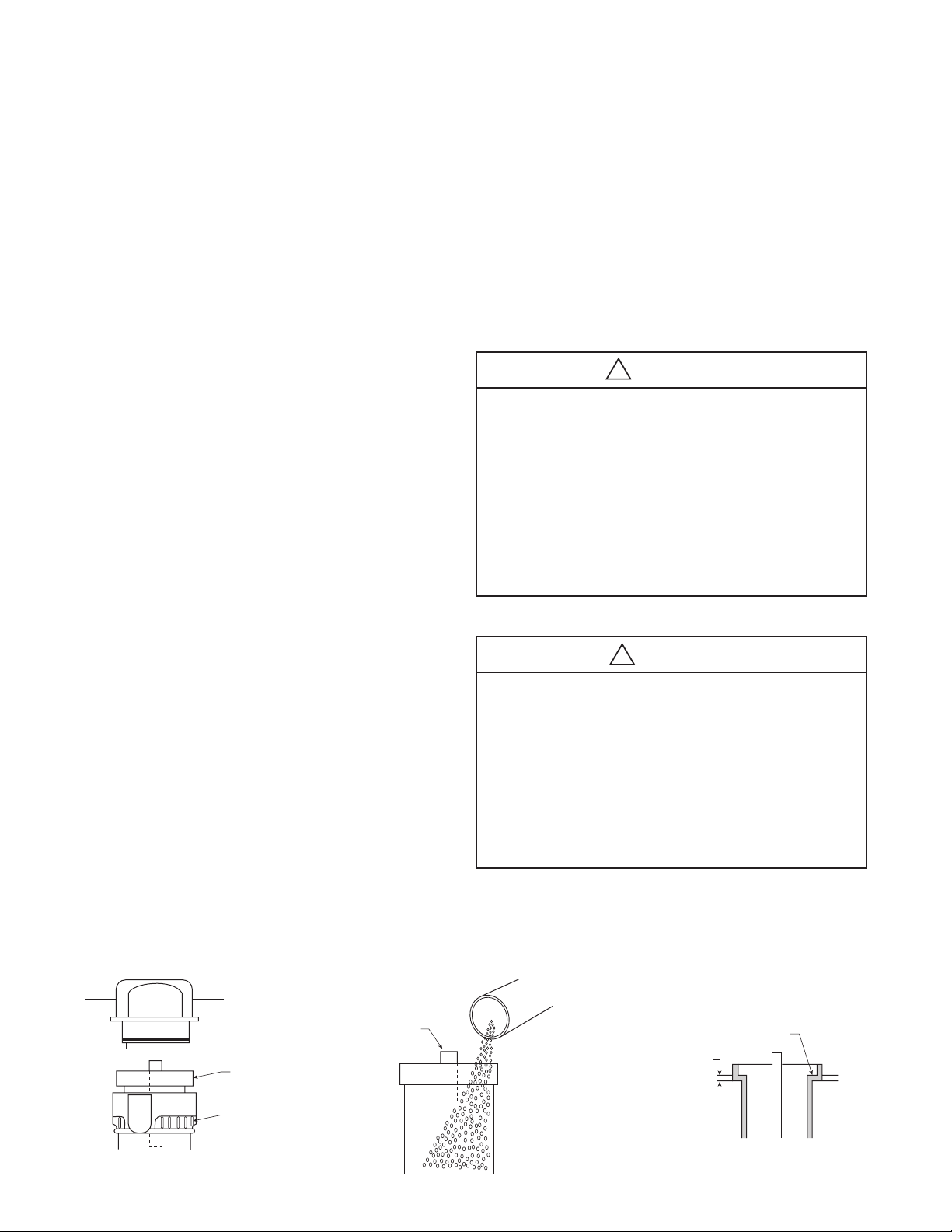
Models X06, X03, X04, and X25
Inner
Step
1/8"
X03 / X04 / X25
Figure 3
Bowl
Clam
p
Ring
X03 / X04 / X25
Figure 1
Keep
Covered
Figure 2
• Coalescing Filter: Should be used prior to the manual desiccant
dryer in any lubricated compressor system which does not utilize
a system coalescing filter. The coalescing filter removes oil from
the compressed air, which prevents the oil from coating the
silica gel or mole sieve and destroying its ability to dry the air.
Oil contaminated desiccant must be replaced and disposed of
properly, as it cannot be regenerated.
• Afterfilter: Should be used after the manual desiccant dryer
in any system where any amount of desiccant dust, however
insignificant, is undesirable. The afterfilter prevents the very
slight desiccant dusting, which occurs over time, from proceeding
downstream into the compressed air system.
• Pre-Dryers: Both the silica gel and mole sieve manual desiccant
dryers can have their drying lives extended through the use of a
pre-dryer. The silica gel (“000”/“M00”) models will typically last
over three times as long if a refrigerated air dryer is placed in the
compressed air system prior to it. (A plant air system refrigerated
dryer will provide the same extended life.) The mole sieve (“U00”/
“MU0”) models will typically last three times as long if a silica gel
(“000”/“M00”) model dryer installed prior to the mole sieve dryer.
(A plant air system desiccant dryer will provide the same extended
life.) Users of either type of manual desiccant dryer who expect
a high air flow demand may wish to consider using a pre-dryer.
Please see page 4 for exact model recommendations.
Operation
1. The silica gel desiccant, when visible through the clear
polycarbonate plastic bowl, contains a color indicator. It changes
from Blue (meaning dry) to Pink (meaning wet) to indicate the need
to replace or regenerate the desiccant. (An X05-02-000 moisture
indicator can be used with 4A molecular sieve units to perform the
same function.) On units with metal bowls, a moisture indicator
mounted on the cover performs the same color changing function.
2. The 4A molecular sieve does not change color. For moisture
indication an X05-02-000 is recommended. See page 4.
3. Environment friendly disiccant changes color from yellow (meaning
dry) to green (meaning wet).
3. By installing two or more units in parallel, higher dry airflows can be
achieved.
Maintenance
1. The only servicing required for silica gel units is when the desiccant
color or moisture indicator has changed from Blue (meaning dry) to
Pink (meaning wet). Should this color change occur:
a. Turn off and depressurize the line containing the dryer unit.
b. Loosen the clamp ring and remove the bowl from the top housing.
(Figure 1) Proceed to step 2 or 3, as required.
2. Desiccant replacement:
a. Pour out used desiccant.
b. Open new container and refill bowl. (Figure 2)
c.
Shake or tap bowl to settle desiccant. Add or remove sufficient
quantity to fill Model X03 and X25 unit bowl to 1/8" below inner
step, and for Model X06 fill bowl to within 1/2" of the top. (Figure 3)
!
WARNING
FAILURE OR IMPROPER SELECTION OR IMPROPER USE OF THE
PRODUCTS AND/OR SYSTEMS DESCRIBED HEREIN OR RELATED ITEMS
CAN CAUSE DEATH, PERSONAL INJURY AND PROPERTY DAMAGE.
This document and other information from The Company, its subsidiaries
and authorized distributors provide product and/or system options for further
investigation by users having technical expertise. It is important that you analyze
all aspects of your application, including consequences of any failure and review
the information concerning the product or systems in the current product catalog.
Due to the variety of operating conditions and applications for these products
or systems, the user, through its own analysis and testing, is solely responsible
for making the final selection of the products and systems and assuring that all
performance, safety and warning requirements of the application are met.
The products described herein, including without limitation, product features,
specifications, designs, availability and pricing, are subject to change by The
Company and its subsidiaries at any time without notice.
EXTRA COPIES OF THESE INSTRUCTIONS ARE AVAILABLE FOR INCLUSION
IN EQUIPMENT / MAINTENANCE MANUALS THAT UTILIZE THESE PRODUCTS.
CONTACT YOUR LOCAL REPRESENTATIVE.
!
CAUTION
Polycarbonate bowls, being transparent and tough, are ideal for use with Filters
and Lubricators. They are suitable for use in normal industrial environments, but
should not be located in areas where they could be subjected to direct sunlight,
an impact blow, nor temperatures outside of the rated range. As with most
plastics, some chemicals can cause damage. Polycarbonate bowls should not
be exposed to chlorinated hydrocarbons, ketones, esters and certain alcohols.
They should not be used in air systems where compressors are lubricated with
fire-resistant fluids such as phosphate ester and di-ester types.
Metal bowls are recommended where ambient and/or media conditions are
not compatible with polycarbonate bowls. Metal bowls resist the action of most
such solvents, but should not be used where strong acids or bases are present
or in salt laden atmospheres. Consult the factory for specific recommendations
where these conditions exist.
TO CLEAN POLYCARBONATE BOWLS USE MILD SOAP AND WATER
ONLY! DO NOT use cleansing agents such as acetone, benzene, carbon
tetrachloride, gasoline, toluene, etc., which are damaging to this plastic.
Bowl guards are recommended for added protection of polycarbonate bowls where
chemical attack may occur.
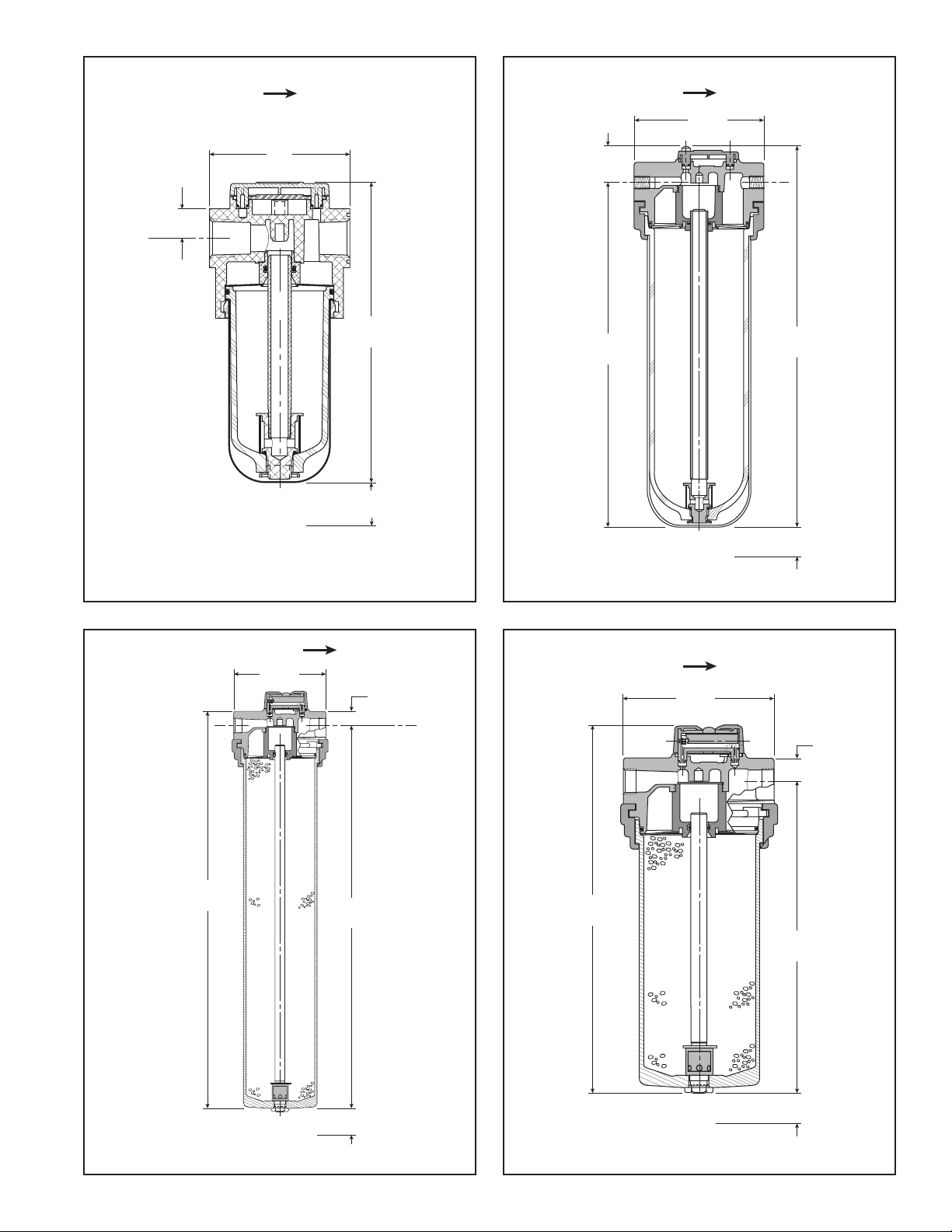
3
Flow
19.58
(497)
4.79
(122.6)
2.0
(50.8)
Bowl
Removal
Clearance
21.28
(540.5)
0.71
(18.26)
C
L
Model X25 with Metal Bowl
12.25
(311.1)
11.05
(281)
1.20
(30)
4.63
(117.60)
Flow
2.0
(50.8)
Bowl
Removal
Clearance
6.41
(163)
3.00
(76)
Flow
1.00
(25.4)
1.50
(38.1)
Bowl
Removal
Clearance
C
L
8.30
(211)
10.00
(254)
0.71
(18.26)
4.79
(122.6)
Flow
2.0
(50.8)
Bowl
Removal
Clearance
Model X06 Model X03 with Plastic Bowl
Model X03 with Metal Bowl
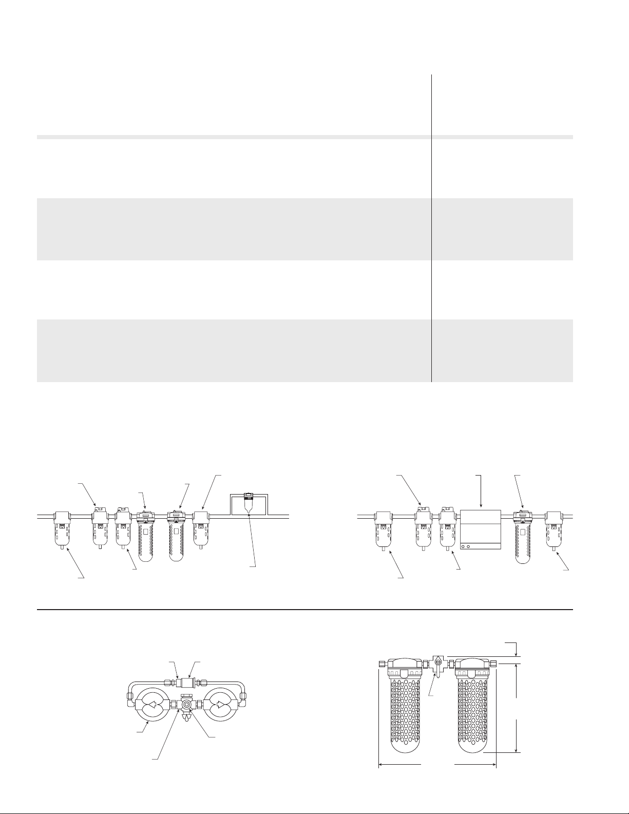
4
X04-02-000 Dryer
1/4" NPT
Outlet Port (On Bottom
Of Shuttle Valve)
X03-02-000
Desiccant Dryer
(2 Required)
Upper Port In 4-Way
Valve To Be Open To
Atmosphere
Shuttle Valve
1/4"
NPT
Inlet
Port
4-Way Valve
14.42"
(366 mm)
12.65"
(322 mm)
0.94"
(23.8 mm)
“U00”/“MU0” Models: “000”/“M00” Models:
“000” Model
Dryer
Afterfilter Refrigerated
Air Dryer
(If desired)
“U00” Model
Pre-Dryer/
(If desired)
“U00” Model
Dryer
Prefilter(s)
(If desired)
X05-02-000
Moisture Indicator
Coalescing
Filter
Liquid
Separator
(If desired)
Liquid
Separator
(If desired)
Prefilter(s)
(If desired)
Slight restriction
(if necessary)
to assure at least
1 SCFM through X05
Moisture Indicator
Coalescing
Filter
Afterfilter
Typical Installation Arrangement For Manual Dryers
Recommended Liquid Separators, Filters and Pre-Dryers
(use as necessary for specific system requirements)
Pre-Drying Total
Manual Desiccant Desiccant
Manual Desiccant Particulate Coalescing or Refrigerated Life if
Dryer Liquid Filter/Separator Filter Afterfilter Air Dryer, For Pre-Drying
Model Used Separator (5 micron) (0.5 micron) (0.5 micron) Extended Life Dryer Used
Silica Gel
For -45°F (-42°C)
Atmospheric
Dewpoint:
X06-02-000 WSA-02-FM0 F16-02-F00 M16-02-FS0 AF1-02-S00 WRA-0010 2200 SCF
X03-XX-000/M00 WSA-XX-FM0 F16-XX-F00/M00 M16-XX-FS0/MS0 AF1-XX-S00 WRA-0010 16,000 SCF
X04-02-000 WSA-02-FM0 F16-02-F00 M16-02-FS0 AF1-02-S00 WRA-0010 32,000 SCF
(16,000x2)
X25-04-000 WSA-04-FM0 F26-04-FM0 M26-04-FMS AF2-04-S00 WRA-0025 40,000 SCF
Type 4A Molecular Model
Sieve For -100°F (-73°C)
Atmospheric Dewpoint:
X06-02-U00 WSA-02-FM0 F16-02-F00 M16-02-FS0 AF1-02-S00 X06-02-000 1800 SCF
X03-XX-U00/MU0 WSA-XX-FM0 F16-XX-F00/M00 M16-XX-FS0/MS0 AF1-XX-S00 X03-XX-000/M00 13,200 SCF
X04-02-U00 WSA-02-FM0 F16-02-F00 M16-02-FS0 AF1-02-S00 X04-02-000 26,400 SCF
(13,200x2)
X25-04-U00 WSA-04-FM0 F26-04-FM0 M26-04-FMS AF2-04-S00 X25-04-000 33,000 SCF
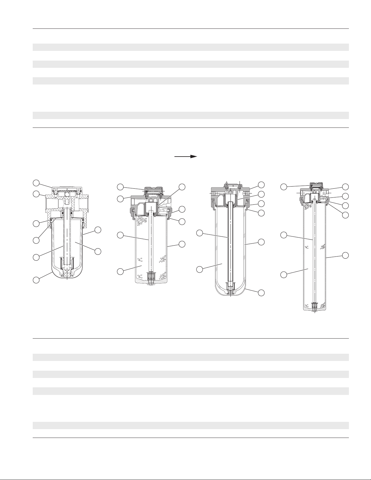
5
1
8
3
2
5
6
4
7
MODEL X06
MODEL X03 WITH
METAL BOWL
7
1
3
2
5
8
4
6
7
1
3
2
5
8
4
6
MODEL X03/X04 WITH
TRANSPARENT BOWL
7 1
8
2
5
3
4
6
MODEL X25 WITH
METAL BOWL
Replacement Parts List – METAL BOWL Units with Moisture Indicators
Description Part No. Qty. Part No. Qty.
X03 X25
1 Cover NNR — NNR —
2 Screen Assembly GRP-96-434 1 GRP-96-434 1
3 Bowl O-Ring GRP-95-256 1 GRP-95-256 1
4 Tube Assembly w/Screen DRP-96-451 1 DRP-95-622 1
5 Metal Bowl DRP-96-450 1 NNR —
6 Silica Gel (000) DRP-85-059 8 Bags / 7 lbs. DRP-85-280 8 Bags / 7 lbs.
4A Molecular Sieve (U00) DRP-85-060 8 Bags / 7 lbs. DRP-95-624 8 Bags / 7 lbs.
13x Molecular Sieve (X00) DRP-85-061 8 Bags / 7 lbs. N/A —
Environment Friendly (E00) DRP-85-447 8 Bags / 7 lbs. DRP-85-447 8 Bags / 7 lbs.
7 Moisture Indicator ** DRP-95-623 1 DRP-95-623 1
8 Clamp Ring GRP-96-404 1 GRP-96-404 1
NNR: Not normally replaced
** The moisture indicator contains a weep orifice to provide an air sample to the moisture indicating paper.
Air leakage from this indicator is necessary and normal.
Replacement Parts List — TRANSPARENT BOWL Units with Bowl Guards
Description Part No. Qty. Part No. X03 X04
X06 Qty. Qty.
1 Cover NNR — NNR — —
2 Screen Assembly NNR — NNR 1 2
3 Bowl O-Ring GRP 95-259 1 GRP-95-256 1 2
4 Tube Assembly w/screen N/A 1 DRP-96-435 1 2
5 Transparent Bowl N/A 1 GRP-95-871 1 2
6 Silica Gel (000) DRP-95-303 3 Bags / .75 lbs. DRP-85-059 8 Bags / 7 lbs. 8 Bags / 7 lbs.
4A Molecular Sieve (U00) DRP-95-304 3 Bags / .75 lbs. DRP-85-060 8 Bags / 7 lbs. 8 Bags / 7 lbs.
13x Molecular Sieve (X00) DRP-95-305 3 Bags / .75 lbs. DRP-85-061 8 Bags / 7 lbs. 8 Bags / 7 lbs.
Environment Friendly (E00) DRP-85-448 3 Bags / .75 lbs. DRP-85-447 8 Bags / 7 lbs. 8 Bags / 7 lbs.
7 Bowl Guard GRP-95-846 1 DRP-95-810 1 2
8 Clamp Ring NNR — GRP-96-404 1 2
FLOW (all units)

6
Customer/Technical Service
Pneumatic Division
Richland, MI 49083
Tel: (269) 629-2550
Fax: (269) 629-2475
WILKERSON WARRANTY
Wilkerson products are warranted to be free from defects in material
and workmanship, under proper use, installation, application and
maintenance in accordance with Wilkerson's written recommendations
and specification for a period of one year from the date of shipment from
the factory (refrigerated dryers are warranted for 2 years). Wilkerson's
obligation under this warranty is limited to, and the sole remedy for any
such defect shall be, the repair or replacement (at Wilkerson's option)
of unaltered products returned to Wilkerson and proven to have such
defect, provided such defect is promptly reported to Wilkerson within
said one-year period.
This is the only authorized Wilkerson Warranty and is in lieu of all
other express or implied warranties or representations, including
any implied warranties of merchantability or fitness, or of any
other obligations on the part of Wilkerson.
Warranty claims must be submitted and shall be processed in
accordance with Wilkerson's established warranty claim procedure.
In no event will Wilkerson be liable for business interruptions, loss of
profits, personal injury, costs of delay or for any other special, indirect,
incidental or consequential losses, cost or damages.
WARNING: USE LIMITATIONS
Wilkerson's warranties are void, and Wilkerson assumes no
responsibility for any resulting cost, loss, injury or any other damages
whatsoever, with respect to any plastic bowl unit for which a bowl
guard is standard equipment if the unit is placed in service without the
bowl guard and, except as otherwise specified in writing by Wilkerson,
with respect to any Wilkerson products which are used in other than
compressed air service. Specific warnings with respect to these and
other use limitations appear elsewhere in this catalog.
Wilkerson maintains a policy of ongoing product development
and improvement. We therefore reserve the right to change
dimensions specification and design without notice.
DO NOT PLACE PLASTIC BOWL UNIT IN SERVICE
WITHOUT BOWL GUARD INSTALLED
Plastic bowl units are sold only with bowl guards with the exception
to miniature units (C04, F00, L00, and M00). To minimize the danger
of flying fragments in the event of plastic bowl failure, the bowl guards
should not be removed. If the unit is in service without the bowl guard
installed, manufacturer's warranties are void, and the manufacturer
assumes no responsibility for any resulting loss.
If the unit has been in service and does not have a bowl guard,
order one and install before placing back in service.
CAUTION
Certain compressor oils, chemicals, household cleaners, solvents,
paints and fumes will attack plastic bowls and can cause bowl failure.
Do not use near these materials. When bowl becomes dirty replace
bowl or wipe only with a clean, dry cloth. Reinstall bowl guard or buy
and install a bowl guard. Immediately replace any crazed, cracked,
damaged or deteriorated plastic bowl with a bowl or a new plastic bowl
and bowl guard.
CAUTION
Except as otherwise specified by the manufacturer, this product is
specifically designed for compressed air service, and use with any
other fluid (liquid or gas) is a misapplication. For example, use with or
injection of certain hazardous liquids or gases in the system (such as
alcohol or liquid petroleum gas) could be harmful to the unit or result
in a combustible condition or hazardous external leakage. Before using
with fluids other than air, or for non-industrial applications, or for life
support systems, consult Wilkerson Corporation for written approval.
SOME OF THE MATERIALSTHATWILL ATTACK
POLYCARBONATE PLASTIC BOWLS.
Acetaldehyde Chlorobenzene Methylene chloride
Acetic acid (conc.) Chloroform Methylene salicylate
Acetone Cresol Milk of lime (CaOH)
Acrylonitrile Cyclohexanol Nitric acid (conc.)
Ammonia Cyclohexanone Nitrobenzene
Ammonium fluoride Cyclohexene Nitrocellulose lacquer
Ammonium hydroxide Dimethyl formamide Phenol
Ammonium sulfide Diozane Phosphorous hydroxy
Anaerobic adhesives Ethgane tetrachloride chloride
and sealants Ethyl acetate Phosphorous trichloride
Antifreeze Ethyl ether Propionic acid
Benzene Ethylamine Pyridine
Benzoic acid Ethylene chlorohydrin Sodium hydroxide
Benzyl alcohol Ethylene dichloride Sodium sulfide
Brake fluids Ethylene glycol Styrene
Bromobenzene Formic acid (conc.) Sulfuric acid (conc.)
Butyric acid Freon (refrig. & Propell.) Sulphural chloride
Carbolic acid Gasoline (high aromatic) Tetrahydronaphthalene
Carbon disulfide Hydrazine Tiophene
Carbon tetrachloride Hydrochloric acid (conc.) Toluene
Caustic potash solution Lacquer thinner Turpentine
Caustic soda solution Methyl alcohol Xylene
Perchlorethylene
& Others
TRADE NAMES OF SOME COMPRESSOR OILS, RUBBER
COMPOUNDS AND OTHER MATERIALSTHATWILL ATTACK
POLYCARBONATE PLASTIC BOWLS.
Atlas “Perma-Guard” National Compound #N11
Buna N “Nylock” VC-3
Cellulube #150 and #220 Parco #1306 Neoprene
Crylex #5 cement *Permabond 910
*Eastman 910 Petron PD287
Garlock #98403 (polyurethane) Prestone
Haskel #568-023 Pydraul AC
Hilgard Co.'s hil phene Sears Regular Motor Oil
Houghton & Co. oil #1120, Sinclair oil “Lily White”
#1130 & #1055 Stauffer Chemical FYRQUEL #150
Houtosafe 1000 Stillman #SR 269-75 (polyurethane)
Kano Kroil Stillman #SR 513-70 (neoprene)
Keystone penetrating oil #2 Tannergas
*Loctite 271 Telar
*Loctite 290 Tenneco anderol #495 & #500 oils
*Loctite 601 Titon
*Loctite Teflon-Sealant *Vibra-tite
Marvel Mystery Oil Zerex
Minn. Rubber 366Y
*When in raw liquid form.
We cannot possibly list all harmful substances, so check with
Mobay or the General Electric office for further information on
polycarbonate plastic.
The trade names “EconOmist” and “Flow-Guide”
are registered at the United States Patent Office.
“Auto-Fill”, “Dial-Air”, “Flex-Drain”, “Mainliner” and
“Whirl-Flo” are trade names of the Wilkerson Corporation.
WILKERSON PRODUCTS ARE PROTECTED BY THE
FOLLOWING U.S. PATENT AND PATENTS IN OTHER
COUNTRIES, ADDITIONAL PATENTS ARE PENDING.
3,631,878 3,667,493 3,762,224 4,215,790
4,215,790 3,793,803 4,718,245 3,793,803
3,858,403 D-292-310 D-229-629 4,215,790
4,289,335 4,352,511 4,559,065 4,631,073
4,689,969 4,696,320 3,889,484 3,945,465
4,631.073 D-234-848
 Loading...