


XL™ Series
Models H-350XL™
H-500XL™
H-510XL™
H-522
H-522 - Plus
Owner’s Manual

XL™ Series
Data Logger /
Data Collection Platform
Owner’s Manual
Revision: 2.14 - 000
NOTICE
This product embodies technology that is confidential and proprietary technology of DESIGN
ANALYSIS ASSOCIATES, INC., and which is protected by United States copyright laws and
international copyright treaty provisions, and/or by contract and applicable laws of trade secrecy.
These include all Software, Printed Circuit Board Artwork, Schematic Diagrams, and
Technologies applied therein. The enclosure encasing the electronics of this instrument may not
be opened without written consent of DESIGN ANALYSIS ASSOCIATES, INC., and any
attempt to do so without such written authorization constitutes a breach of contract and will also
void any applicable warranty for the product.
Design Analysis Associates, Inc.
75 West 100 South
Logan, UT 84321 USA
Phone: (435) 753-2212
Fax: (435) 753-7669
Internet: www.waterlog.com
E-mail: sales@waterlog.com

Table of Contents
User Agreement/WATERLOG Warranty.........................................®W-1
Chapter 1 Introduction
1.1 Introduction to the XL™ Series Data Logger. . . . . . . . . . . . . . . . . . . . . . . . . . . . . . . . . . . 1-1
1.2 Unpacking the XL™ Series Data Logger. ..................................... 1-2
1.3 Modes Of Operation. ..................................................... 1-3
1.3.1 SDI-12 Sensor Mode..................................................... 1-3
1.3.2 Data Logger / DCP Master Mode........................................... 1-3
1.3.3 Operation Using Auxiliary Outputs. ........................................ 1-4
1.3.4 Operation With The H-355 Gas Purge System (Bubbler). . . . . . . . . . . . . . . . . . . . . . . . 1-4
1.4 About this Manual........................................................ 1-4
1.5 Advanced Manual Sections................................................. 1-4
1.6 Web Page Support........................................................ 1-4
Chapter 2 Hardware Options and Installation
2.1 Mechanical Mounting. .................................................... 2-1
2.2 Front Panel Description.................................................... 2-1
2.2.1 Earth Ground Lug....................................................... 2-2
2.2.2 Pressure Reference Port (Vent)............................................. 2-2
2.2.3 Pressure Port (Input)..................................................... 2-2
2.2.4 GOES Antenna Output................................................... 2-3
2.2.5 GPS Antenna Connector.................................................. 2-3
2.2.3.1 Sample Installation for the Conoflow System. . . . . . . . . . . . . . . . . . . . . . . . . . . . . . . . 2-4
2.2.3.2 Making the Pressure Connection to the H-355 Bubbler. . . . . . . . . . . . . . . . . . . . . . . . 2-5
2.2.6 Bubbler / Aux Port. ..................................................... 2-6
2.2.7 RS-232 Ports........................................................... 2-7
2.2.8 Analog Input Section. ................................................... 2-8
2.2.8.1 Analog Input Channels.................................................. 2-8
2.2.8.2 Analog Grounds....................................................... 2-8
2.2.8.3 Switched +5 Volt Reference Excitation.. . . . . . . . . . . . . . . . . . . . . . . . . . . . . . . . . . . . 2-9
2.2.9 Wind Speed Input (AC Frequency Input). . . . . . . . . . . . . . . . . . . . . . . . . . . . . . . . . . . . . 2-9
2.2.10 Event Counter Input................................................... 2-10
2.2.11 4 to 20 Milliamp Output................................................ 2-11
2.2.12 Digital I/O 1 and 2. ...................................................2–12
2.2.13 SDI-12 Section....................................................... 2-13
2.2.14 Power Connections.................................................... 2-14
2.3 Testing the Installation.................................................... 2-14
2.4 Hardware Revision Detection.............................................. 2-15

Chapter 3 Using The Built In keypad / Display
3.1 Overview............................................................... 3-1
3.2 Keypad/Display Operation.................................................. 3-1
3.3 Familiarization........................................................... 3-6
3.4 Main Menu Description.................................................... 3-7
Chapter 4 Using the PC Menu Interface Operation
4.1 PC Menu Interface........................................................ 4-1
4.2 PC Menu General Operations. .............................................. 4-2
4.3 Main Menu Screen........................................................ 4-3
Chapter 5 General System Options
5.1 Overview............................................................... 5-1
5.2 System Setup............................................................ 5-1
5.3 Time Sync Options........................................................ 5-5
5.4 Advanced System Setup Options............................................. 5-8
Chapter 6 Serial Port Options
6.1 Introduction. ............................................................ 6-1
6.2 Serial Port Menus......................................................... 6-1
6.3 Serial Port Hardware Description. ........................................... 6-6
6.4 Serial Port Functions...................................................... 6-7
Chapter 7 System Configuration Files
7.1 Overview............................................................... 7-1
7.2 Configuration Files Menus. ................................................ 7-1
7.3 Sample Configuration File.................................................. 7-3
Chapter 8 System Status Menus / Optioons
8.1 Status Options Overview................................................... 8-1
8.2 Status Menus............................................................ 8-1
8.3 Status Screen Operations................................................... 8-2

Chapter 9 Scanning Options
9.1 Introduction. ............................................................ 9-1
9.2 Scanning Menus.......................................................... 9-1
9.3 Scanning Options......................................................... 9-1
Chapter 10 Stage Menus / Options
10.1 Stage Sensor and Remote Stage Setup....................................... 10-1
10.2 Stage / Temperature Menus (H-350XL Only). . . . . . . . . . . . . . . . . . . . . . . . . . . . . . . . . 10-1
10.3 Stage Options (H-350XL / H-510XL Only). . . . . . . . . . . . . . . . . . . . . . . . . . . . . . . . . . 10-2
10.4 PtTemp Sensor Setup (H-350XL Only)...................................... 10-4
10.5 Remote Stage Setup Overview. ...........................................10-5
10.6 Remote Stage Menus.................................................... 10-5
10.7 Remote Stage Options................................................... 10-5
Chapter 11 Analog Inputs / 5 Volt Excitation
11.1 Analog Inputs Overview. ................................................ 11-1
11.2 Analog Menus......................................................... 11-1
11.3 Analog Options. ....................................................... 11-2
11.4 Analog Input Connections................................................ 11-4
11.4.1 Analog Inputs and Analog Ground Connections. . . . . . . . . . . . . . . . . . . . . . . . . . . . . 11-4
11.4.2 Switched +5.00 Volt Reference Excitation.. . . . . . . . . . . . . . . . . . . . . . . . . . . . . . . . . 11-5
11.5 Analog Input Setup Examples............................................. 11-6
11.6 Two Point Calibration Basics. ............................................ 11-7
Chapter 12 Digital I/O
12.1 Digital I/O Overview.................................................... 12-1
12.2 Digital I/O Menus. ..................................................... 12-1
12.3 Digital I/O Options...................................................... 12-2
12.4 Quadrature Shaft Encoder Options. ........................................12-7
Chapter 13 Counter And frequency Inputs
13.1 Introduction. .......................................................... 13-1
13.2 Counter and Frequency Menus. ........................................... 13-1
13.3 Counter Options........................................................ 13-2
13.4 Frequency Options...................................................... 13-6

Chapter 14 SDI-12 Operations
14.1 SDI-12 Overview....................................................... 14-1
14.2 SDI-12 Transparent Mode and Full Screen Mode. . . . . . . . . . . . . . . . . . . . . . . . . . . . . . 14-1
14.3 SDI-12 Data Logger Mode................................................ 14-6
14.4 SDI-12 Sensor Mode.................................................... 14-9
14.5 H310 Setup........................................................... 14-12
14.6 H330 / H331 Setup..................................................... 14-14
14.7 SDI-12 Sensor Mode Supported Commands.. . . . . . . . . . . . . . . . . . . . . . . . . . . . . . . . 14-16
14.7.1 SDI-12 Command and Response Protocol. . . . . . . . . . . . . . . . . . . . . . . . . . . . . . . . . 14-17
14.7.2 Standard SDI-12 Command Set ......................................... 14-18
14.7.3 Send Acknowledge Command .......................................... 14-18
14.7.4 Send Identification Command .......................................... 14-19
14.7.5 Measure Command . ................................................. 14-20
14.7.6 Initiate Verify Command .............................................. 14-22
14.7.7 Send Data Command ................................................. 14-23
14.7.8 Change Sensor Address ............................................... 14-24
14.7.9 Extended SDI-12 Command Set . ....................................... 14-24
14.7.10 Write “User Units Slope” Command .. . . . . . . . . . . . . . . . . . . . . . . . . . . . . . . . . . . 14-25
14.7.11 Write “User Units Offset” Command . . . . . . . . . . . . . . . . . . . . . . . . . . . . . . . . . . . 14-26
14.7.12 Read “User Units Slope” Command . . . . . . . . . . . . . . . . . . . . . . . . . . . . . . . . . . . . 14-27
14.7.13 Read “User Units Offset” Command .. . . . . . . . . . . . . . . . . . . . . . . . . . . . . . . . . . . 14-28
Chapter 15 Logging Options
15.1 Logging Overview...................................................... 15-1
15.2 Logging Options Menu. ................................................. 15-1
15.3 Logging Options. ...................................................... 15-2
Chapter 16 Operation with the GOES Radio
16.1 Introduction. .......................................................... 16-1
16.1.1 GOES Radio Data Connection........................................... 16-1
16.1.2 GOES Radio Types.................................................... 16-1
16.2 Configuring the GOES Radio, General Options. . . . . . . . . . . . . . . . . . . . . . . . . . . . . . . 16-3
16.3 GOES Self Timed Options............................................... 16-10
16.4 GOES Random Options................................................. 16-24
16.5 GOES Diagnostics..................................................... 16-28
16.6 GOES Radio Setup Example............................................. 16-31
16.7 GOES Binary Data..................................................... 16-32
16.8 GOES Four Byte Pseudo-Binary Lookup Table. . . . . . . . . . . . . . . . . . . . . . . . . . . . . . 16-34
16.9 Common GOES Terms. ................................................ 16-35
16.10 Julian Day Tables..................................................... 16-37
16.11 GOES Downlink Message Header Basics. . . . . . . . . . . . . . . . . . . . . . . . . . . . . . . . . . 16-39

Chapter 17 ALERT Radio Operation
17.1 Introduction. .......................................................... 17-1
17.2 ALERT Menus......................................................... 17-1
17.3 ALERT Options........................................................ 17-2
17.4 Special Cases For ALERT Transmissions.. . . . . . . . . . . . . . . . . . . . . . . . . . . . . . . . . . . 17-8
Chapter 18 4 to 20 Milliamp Output
18.1 Introduction. .......................................................... 18-1
18.2 4 To 20 Milliamp Menus................................................. 18-1
18.3 4 To 20 Milliamp Options................................................ 18-1
18.4 4 To 20 Hardware Connections / Wiring. . . . . . . . . . . . . . . . . . . . . . . . . . . . . . . . . . . . . 18-4
Chapter 19 Alarm Call Out
19.1 Overview............................................................. 19-1
19.2 Alarm Call Out Menus................................................... 19-1
Chapter 20 Data Card Options
20.1 Data Card Options...................................................... 20-1
20.2 Data Card / Memory Options.............................................. 20-2
Chapter 21 Operation With the H-355 "Smart Gas" System
21.1 Introduction to the H-355................................................. 21-1
21.2 H-355 Menus.......................................................... 21-1
21.3 H-355 Options......................................................... 21-2
21.4 H-355 Configuration Drawing............................................. 21-7
Chapter 22 Functions
22.1 Introduction. .......................................................... 22-1
22.2 Function Menu......................................................... 22-1

Chapter 23 XL-Basic Programming Guide
Version Changes Information. ................................................. 23-1
Main Program Variables. ..................................................... 23-2
General Purpose Variables............................................... 23-2
Standard Input Variables................................................ 23-3
Read Only Variables. .................................................. 23-4
Math Functions. ............................................................ 23-5
XL-Basic Command Summary. ................................................ 23-6
XL-Basic Language Descriptions. .............................................. 23-8
Creating XL-Basic Programs.................................................. 23-18
XL-Basic Menu Screens. .................................................... 23-18
Example Program #1........................................................ 23-20
Example Program #2........................................................ 23-21
Chapter 24 Maintenance / Troubleshooting
24.1 Maintenance........................................................... 24-1
24.2 Troubleshooting........................................................ 24-1
Appendix A XL Series Specifications. ......................................... A-1
Appendix B Blank...........................................................B-1
Appendix C Remote Operation (Command Mode).................................C-1

User Agreement/
WATERLOG Warranty
1. NATURE OF THE PRODUCT
This agreement accompanies a pressure measuring/data collection system comprising firmware,
circuitry and other electronic equipment in an enclosed housing, and packaged together with written
instructional materials. The packaged electronic circuitry and instructional materials herein are
collectively referred to as the “PRODUCT.” The PRODUCT is made available from DESIGN
ANALYSIS ASSOCIATES, INC., of 75 West 100 South, Logan, Utah 84321 (hereinafter referred to as
“DESIGN ANALYSIS”), and contains information and embodies technology that is confidential and
proprietary to DESIGN ANALYSIS, and the availability and use of the PRODUCT is extended to you,
the USER, solely on the basis of the terms of agreement which follow.
2. ACKNOWLEDGMENTS BY USER
Opening the package which encloses the accompanying PRODUCT indicates your acceptance of the
terms and conditions of this agreement and constitutes an acknowledgment by you of the confidential and
proprietary nature of the rights of DESIGN ANALYSIS in the PRODUCT.
3. DUTIES OF YOU, THE USER
In consideration for the access to and use of the PRODUCT extended to you by DESIGN ANALYSIS
and to protect the confidential and proprietary information of DESIGN ANALYSIS, USER agrees as
follows:
®
(a) USER agrees that they will not remove from the exterior of the housing of the
PRODUCT any safety warnings or notices of proprietary interest placed thereon by
DESIGN ANALYSIS.
(b) USER agrees that they shall not disassemble or otherwise reverse engineer the
PRODUCT.
(c) USER agrees to treat the PRODUCT with the same degree of care as USER exercises in
relation to their own confidential and proprietary information.
4. TERM
USER may enjoy these rights only as long as their possession of the PRODUCT shall continue to be
rightful. These rights will cease if the PRODUCT is returned to DESIGN ANALYSIS under the terms of
any redemption offer, warranty, or money-back guarantee, or if USER transfers the PRODUCT to
another party on terms inconsistent with this agreement.
5. LIMITED WARRANTY
(a) What is Covered
DESIGN ANALYSIS warrants that for a period of twelve months from the time of delivery the
functions to be performed by the PRODUCT will be substantially in compliance with USER
documentation. DESIGN ANALYSIS also warrants that the PRODUCT will be free from
defects in materials and workmanship for a period of ONE YEAR from the date of delivery.
XL Series User Agreement/WATERLOG Warranty W-1
®

(b) What USER Must Do
If the product fails to satisfy the above warranty, USER must notify DESIGN ANALYSIS in
writing within the applicable period specified above and reasonably cooperate with the directions
they received from DESIGN ANALYSIS.
(c) What DESIGN ANALYSIS Will Do
DESIGN ANALYSIS will repair the PRODUCT or will endeavor to provide a replacement of
same within a reasonable period of time. In the event that DESIGN ANALYSIS is unable to
make the necessary repairs or replacement within a reasonable period of time, the original
purchase price will be refunded upon the return of the PRODUCT to DESIGN ANALYSIS.
(d) Limitations
(i) THE ENTIRE REMEDY FOR BREACH OF THIS LIMITED WARRANTY
SHALL BE LIMITED TO REPLACEMENT OF THE DEFECTIVE PRODUCT
OR REFUNDING OF THE PURCHASE PRICE, AS SET FORTH ABOVE.
IN NO EVENT WILL THE LIABILITY OF DESIGN ANALYSIS TO USER
OR TO ANY OTHER PARTY EXCEED THE ORIGINAL PURCHASE PRICE
OF THE PRODUCT, REGARDLESS OF THE FORM OF THE CLAIM.
(ii) EXCEPT FOR THE EXPRESS WARRANTIES ABOVE, DESIGN ANALYSIS
SPECIFICALLY DISCLAIMS ALL OTHER WARRANTIES, INCLUDING,
WITHOUT LIMITATION, ALL IMPLIED WARRANTIES OF
MERCHANTABILITY AND FITNESS FOR A PARTICULAR PURPOSE.
(iii) UNDER NO CIRCUMSTANCES WILL DESIGN ANALYSIS BE LIABLE
FOR SPECIAL, INCIDENTAL, CONSEQUENTIAL, INDIRECT, OR ANY
OTHER DAMAGES OR CLAIMS ARISING FROM THE USE OF THIS
PRODUCT, THIS INCLUDES LOSS OF PROFITS OR ANY OTHER
COMMERCIAL DAMAGES, EVEN IF ADVISED OF THE POSSIBILITY OF
SUCH DAMAGES. IN NO EVENT WILL DESIGN ANALYSIS BE LIABLE
FOR ANY CLAIMS, LIABILITY, OR DAMAGES ARISING FROM
MODIFICATION MADE THEREIN, OTHER THAN BY DESIGN
ANALYSIS.
(iv) THIS LIMITED WARRANTY GIVES USER SPECIFIC LEGAL RIGHTS.
USER MAY ALSO HAVE OTHER RIGHTS WHICH VARY FROM STATE
TO STATE. SOME STATES DO NOT ALLOW LIMITATIONS ON HOW
LONG AN IMPLIED WARRANTY LASTS OR THE EXCLUSION OF
INCIDENTAL OR CONSEQUENTIAL DAMAGES, SO THOSE
LIMITATIONS OR EXCLUSIONS MAY NOT APPLY.
6. GOVERNING LAW
This Agreement and its validity and interpretation shall be governed by the laws of the State of Utah,
notwithstanding any choice of law rules of Utah or any other state or jurisdiction.
W-2 User Agreement/WATERLOG Warranty XL Series
®

Chapter 1
Introduction
1.1 Introduction to the XL™ Series Data Logger
The XL Series of data loggers started with the H-350XL and the H-500XL and expanded from
there to a total of five major products, that all use the same basic programming methods and
other common features and functionality. The XL Series of data loggers / DCP’s now includes
the following products.
H-500XL Basic XL Series data logger.
H-350XL Basic XL Series data logger with built in pressure transducer.
H-510XL Basic XL Series data logger with built in shaft encoder.
H-522Plus Basic XL Series data logger with built in GOES HDR transmitter.
H-522 Same as H-522Plus but does not include the built in keypad / display.
Customer driven enhancements have vastly expanded the capabilities of the XL Series products
since its introduction early in 2000. Below is a quick overview of the common features of all the
XL Series data loggers followed by a list of differences for each product.
Uses, Functions, Features, and Attributes of the XL™ Series Data Logger / DCP:
!Operates over a wide temperature range: - 40EF to +140EF (- 40EC to +60EC).
!Easy to use program interface and push button keypad. Programming does not require an
external device (i.e., a laptop computer), although all programming and data retrieval can
be done through the serial port on a PC. (keypad and display not available on the H-522
model).
!Provides a bright, easy-to-read display with automatic power shut-off after 5 minutes.
!Four general purpose analog input channels.
!Switch closure event counter.
!AC frequency counter allows direct input for wind speed sensors, etc.
!Designed to output a 4-20 mA signal (No external module required).
!Three serial ports provide for easy installation of multiple serial devices.
!Complete serial interface provides both a command mode for automated use and a menu
mode for human interaction. Both modes provide complete system programming and data
retrieval.
!Built-in data logging functions which store the data in non-volatile internal memory.
!Common interface support for 100, 300, and 1200 Baud GOES Transmitters.
!Support for basic to complex math operations for non-linear sensors.
!Designed to be compatible with all SDI-12 data loggers, and sensors.
!Packaged in a sealed NEMA 4 enclosure.
!Built in BASIC language interpreter for user defined XL-Basic programs.
XL™ Series Introduction 1-1

Additional Features with the H-350XL™ Model only:
!Precision pressure measurement of dry gas.
!Direct replacement of pressure measurement systems such as the mercury manometer or
other industrial analog sensors.
Additional Features with the H-510XL™ Model only:
!Provides precision measurement based on shaft encoder technology.
(Resolution 1/200 of revolution).
!Provides accurate water level ±0.005 Post (SDI-12).
!Directly replaces ADR systems such as the Fisher Porter, Stevens, or other mechanical
tape recorders.
Additional Feature with the H-522Plus Model only:
!Integrated with a HDR (High Data Rate) GOES radio Transmitter.
Additional Feature with the H-522 Model only:
!Same as the H-522Plus but does not include the built in keypad / display.
!Must be programmed through the serial port connected to a PC
1.2 Unpacking the XL™ Series Data Logger
You should have received the following items:
!The XL™ Series instrument
!2-position power terminal block
!18-position sensor I/O terminal block
!The XL™ Series Owner's Manual
!Wall mounting hardware for the XL™: (4) 10-32 screws, (4) plastic mounting tabs
!Communication cable
!NULL modem adaptor
!Gender changer
Note: If the XL™ Series data logger was shipped on the H-250 mounting board or with other
equipment, additional items may be included, depending on how the unit was purchased.
1.3 Modes of Operation
The XL™ can operate as an SDI-12 sensor, as a data logger, or as a sensor and a data logger
simultaneously. The XL™ is compatible with industrial equipment that does not support SDI-12
1-2 Introduction XL™ Series

communications as well as common telemetry equipment. The XL™ Series is also specially
designed to operate with the H-355 Gas Purge System (Bubbler) for high accuracy pressure
measurement.
1.3.1 SDI-12 Sensor Mode
The XL™ will respond as a sensor to SDI-12 commands sent from an external data logger.
During normal SDI-12 communication, an external data logger issues commands to sensors
attached to the SDI-12 data bus. The command includes a sensor address and a command for the
sensor to perform. All of the sensors attached to the bus will wake up and receive the command,
but only the sensor with the matching address will respond to the command, and all of the other
sensors will return to a low power mode. Details on the SDI-12 commands and responses
supported by the XL™ can be found in Appendix B. When used as an SDI-12 sensor, the main
setup options that may need to be changed are the XL™ sensor address and the data parameters
that will be returned. In several applications, the factory defaults will allow the XL™ to be used
as a sensor ‘out of the box’. Detailed information on the XL™ SDI-12 sensor setup is given in
later chapters.
1.3.2 Data Logger / DCP Master Mode
This mode of operation allows the XL™ to log data at a user-defined interval. The data is stored
internally in non-volatile memory. There are several ways to retrieve data from the XL™.
!The data can be copied to an industry standard ATA FLASH Memory Card.
!The data can be downloaded through the serial port of the XL™ to the hard disk of a PC,
(via direct connection or modem connection).
!Data can be transmitted through the GOES system for near real time operation.
The data recorded to the internal memory is stored as ASCII text with a tabular format ready to
be imported into a spreadsheet, a word processor, decodes, etc. Data options for downloading the
recorded data to an external industry standard ATA FLASH memory card are explained in
chapter 20. Information on accessing the XL™ through the serial port is given in chapter 4, and a
detailed explanation of the GOES operations for retrieving data are given in chapter 16.
1.3.3 Operation Using Auxiliary Outputs
The XL™ can be setup to provide various outputs based on any of the sensor input values. The
Sensor data can be output as a 4 to 20 mA signal, as a quadrature output signal, as ASCII text, or
encoded in a special format for transmission using telemetry equipment. This allows the XL™ to
be compatible with industrial equipment that does not support the SDI-12 protocol. The serial
ports on the XL™ enable it to operate with a GOES Transmitter, a data or voice modem, an
ALERT/IFLOWS radio system, etc. The Digital I/O pins may be configured as outputs in order
to drive an external device through a relay, or to simulate a quadrature shaft encoder output.
XL™ Series Introduction 1-3

1.3.4 Operation with the H-355 Gas Purge System (Bubbler)
The H-355 is a self-contained gas purge system designed to replace mechanical gas purge
systems (Nitrogen tank and Conoflow). The XL™ interfaces with the H-355 via the RS-485
connector marked Bubbler/Aux on the front panel. The XL™ is used to adjust the operating
parameters of the H-355. Refer to Chapter 23 in this manual and to the H-355 manual for a
detailed description of the H-355 operation.
1.4 About this Manual
This manual will show you how to properly install and operate your XL™ Series Data Logger /
DCP. The installation procedures and operational functions are very simple and easy to use.
Please take time to read through the manual, it will help answer most questions you have
concerning the XL™ Series Data Logger / DCP and it’s capabilities. The web page at
http://www.waterlog.com will have manual updates and advanced sections of the manual in PDF
format, allowing customers to print extra copies or newer versions of the manual.
1.5 Advanced Manual Sections
There are a few chapters of the manual that are only needed by a small set of users. To save
paper, time and to avoid confusion, these chapters may not print using the main PDF file, but are
still available on the supplied CD or from the web page. The following are examples of chapters
that may be printed separately.
Appendix C Remote Operation (Command Mode)
This section discusses the command mode interface and list all the commands used to configure
the system. Some users have programmed their own user interface on the PC using the
commands so their users will only see the options that pertain to there applications.
Application Note: NOAA GOES Format
This application note discusses how the H-350XL is used when user mode is set to the NOAA
mode. This mode is used for tidal studies and has a very specific GOES format for data
transmissions.
1.6 Web Page Support
The web page at http://www.waterlog.com will provide ongoing support for the XL™ Series data
loggers and DCP products. This includes advanced sections of the manual, new versions of the
main manual, new firmware updates, brochures, technical notes, PC support software, etc. Also
included is example XL-Basic programs and functions.
1-4 Introduction XL™ Series

Chapter 2
Hardware Options and Installation
2.1 Mechanical Mounting
In this manual, referring to the XL is the same as referring to any of the XL Series data logger /
DCP’s. This chapter describes the basic procedure for installing the XL™. This includes all
wiring and plumbing. For proper installation you will need:
"The XL™ mounting hardware
"Two open end wrenches (7/16", 9/16")(Model H-350XL™ Only)
"Small flat blade screw driver
"Power and communication cables
"The XL™ Series Owner’s Manual
2.2 Front Panel Description
Figure 2-1A shows the wiring panel and illustrates the physical input and output features of the
XL™ Series models H-350XL™, H-500XL™ and the H-510XL™ and briefly describes their
purposes. Figure 2-1B shows the same wiring panel but for the H-522 and the H-522Plus. These
diagrams will help show where you should make connections to your XL™ Series data logger /
DCP.
Figure 2-1A Models H-350XL™/H-500XL™/H-510XL™ Front Panel Description
XL™ Series Hardware Options and Installation 2-1

Figure 4-1B Models H-522/H-522+ Front Panel Description
2.2.1 Earth Ground Lug
Run a heavy gauge (14awg) wire from the GND lug of the XL™ to the Earth ground of the
instrument shelter. If there is no Earth ground, one must be installed. This is most important in
the protection of your electronic equipment. It insures the equipment will function properly.
(PROPER GROUNDING IS A MUST!)
2.2.2 Pressure Reference Port (Vent) (H-350XL™ Model only)
In order to make accurate readings, the H-350XL unit must have a way to measure the
atmospheric pressure. This port provides that function. The user never has to make connections
to, or service this port.
Note: Model H-500XL™ and H-510XL™ only uses this location to secure the wiring panel to
the main box using a large hex bolt.
2.2.3 Pressure Port (Input) (H-350XL™ Model only)
This is the pressurized line input port. The user will connect this line to the H-355 bubbler
system or to the conoflow system. Make sure the pressure on this line does not exceed the limits
of the sensor. The pressure range is listed on the serial number label on the side of the H-350XL.
Note: Model H-500XL™ and H-510XL™ only uses this location to secure the wiring panel to
the main box using a large hex bolt.
2-2 Hardware Options and Installation XL™ Series

2.2.4 GOES Antenna Output (Model H-522 and H-522Plus only)
This is the GOES antenna connector and uses an N-Type connector. The user will connect the
GOES antenna cable to this connector.
Note: Always connect an antenna or a dummy load to this connector when testing the integrated
GOES radio.
2.2.5 GPS Antenna connector (Model H-522 and H-522Plus only)
This is the GPS antenna connector. The user will connect the GPS antenna cable to this
connector.
When using the H-522 or the H-522Plus the GPS receiver will be built into the GOES HDR
radio. The H-522 and H-522Plus units shipping at this time have an Omnisat GOES radio from
Signal Engineering built into them. The GPS receiver will turn on and try to acquire the time
when power is applied to the unit. It will stay on until the time is acquired. Once the time is
acquired the GPS receiver will turn off and schedule the next update to happen in 25 hours and
15 minutes. This non repetitive time prevents the GPS receiver from continually failing due to
some external repeated condition. When the GPS receiver turns on to re-sync the time clock it
will try to do so for 30 minutes before giving up and waiting for the next day. If it misses a
single time sync the GOES radio will still transmit. The GOES radio will stop transmitting if
seven consecutive GPS time syncs have been missed. On the seventh time sync attempt the GPS
receiver will not power down after 30 minutes but will stay on trying to re-sync the time clock
and will only power down after it is successful.
When an Omnisat GOES radio is used externally with other XL Series data loggers the same
functionality will exist. This will be discussed in a later chapter.
XL™ Series Hardware Options and Installation 2-3

2.2.3.1 Sample Installation for the Conoflow System (H-350XL only)
Figure 2-2 shows a typical H-350XL™ installation for water depth measurement using the
Conoflow gas purge system. To install the H-350XL™, secure it to the wall of the instrument
shelter or bench top using the provided mounting hardware. This will prevent it from moving or
shifting and pulling on the wires and tubing connected to other equipment. The H-350XL™
should be mounted so moisture and dust will not settle on the main I/O panel. Normally
vertically is the best with the main I/O panel facing down and the display keypad facing out.
DIFFERENTIAL
H-350XL™
MOUNT
ON WALL
REGULATOR
FEEDBACK TUBE
20 - 30 PSI
PRESSURE
RELIEF VALVE
GAS PURGE
LINE ORIFICE
POWER
30 BUBBLES
PER MINUTE
TO RIVER
SITE-FEED
GAS PRESSURE
TO MANOMETER
REGULATOR
Figure 2-2 Conoflow Gas Purge Stream Gauge Installation
NITROGEN
SUPPLY
CYLINDER
2-4 Hardware Options and Installation XL™ Series

2.2.3.2 Making the Pressure Connection to the H-355 Bubbler System (H-350XL only)
Figure 2-3 illustrates the correct procedure for installing the pressure port fittings between the
H-350XL™ and the H-355 Gas Purge System. Chapter 23 goes into more detail on the Gas Purge
System. Refer to the manual provided with the H-355 for installation information.
Connect the pressure input line between the H-350XL™ and the H-355 bubbler system using the
H-350XL™ Install kit, which includes all the required hardware. You will need a 1/8" NPT male
tubing fitting for the pressure input port. It is recommended that you use 1/8" copper tubing. The
proper ferrules must be used to insure there are no leaks. The male 1/8" NPT fitting screws into
the pressure input port of the H-350XL™ connector panel shown in Figure 2-1. On the bubbler
manifold you will need a corresponding tubing fitting. Generally, a 1/4" NPT female to 1/8"
tubing fitting is required. The NPT threads of these fittings need a coat of Teflon tape or
anaerobic thread dope. This helps in preventing leaks.
Figure 2-3. H-350XL / H-355 Combination Installation
XL™ Series Hardware Options and Installation 2-5

2.2.6 Bubbler / Aux Port
Figure 2-4 is the Bubbler / Aux communication port, which is a 6-pin connector that interfaces
with the H-355 Gas Purge System and other WATERLOG products. The XL™ menu is setup to
®
give the user full control of the H-355 system. As other auxiliary devices are developed to
interface with the XL™, they too will be controlled through the XL™ menu system. This port
uses RS-485 hardware for communicating with the auxiliary devices. This provides noise
immunity and multi drop capability. As other devices are used, the cable will be daisy chained
from one device to the next.
Figure 2-4 Bubbler / Auxiliary Output connector pin out
The H-355 is normally used with the H-350XL because it has the built in pressure transducer.
However the H-355 may be used with any of the XL series data loggers and an H-350 Lite or
similar sensor to collect water level data.
2-6 Hardware Options and Installation XL™ Series

2.2.7 RS-232 Ports
The three RS-232 ports are used to connect to a PC, GOES Transmitter, modem, remote display,
or other serial equipment for standard serial communications. These ports are configured as a
DTE type of device. This means they will plug directly into a modem (a DCE type device), but
will require a NULL modem adaptor if connected to a PC (a DTE type device). The NULL
modem cable crosses the communication lines allowing two similar devices to communicate.
Figure 2-5 shows the pin out for all three ports. See the chapter covering the serial ports for
complete information on the port operations.
Figure 2-5 RS-232 Connector
SERIAL PORT PIN-OUT
PIN DIRECTION NAME
1 Input Data Carrier Detect (DCD)
2 Input Receive Data (RD)
3 Output Transmit Data (TD)
4 Output Data Terminal Ready (DTR)
5 Ground (GND)
6 Input Data Set Ready (DSR)
7 Output Request To Send (RTS)
8 Input Clear To Send (CTS)
9 Input Ring Indicator (RI)
XL™ Series Hardware Options and Installation 2-7

2.2.8 Analog Input Section
The first seven connections on the twenty pin terminal block are used for analog input functions.
This includes four analog inputs, two analog grounds and one +5.00 volt excitation connection.
Figure 2-6 Analog Input Section
2.2.8.1 Analog Input Channels
There are four analog input channels labeled Vin1 to Vin4. The standard input range for all
channels is 0 to 5 volts, and the optional range is 0 to 500 millivolts. The 500 millivolt range is
used for sensors that produce millivolt outputs. For example, some solar radiation sensors have a
full scale output of less than 500 millivolts. This type of sensor should be used with the 500
millivolt range. Channels 1 and 2 can also be used in a differential mode. The analog inputs use
a 20 bit analog to digital converter.
2.2.8.2 Analog Grounds
There are two analog ground connection points. In order to preserve signal integrity, it is
important to use the analog grounds only for sensors connected to the analog section of the
XL™. The current flowing through an analog sensor is relatively small and normally very stable.
This provides stable voltages produced by these sensors. If a digital sensor has its ground
connection tied into the analog ground, the currents from the digital sensor will flow through the
analog circuitry causing voltage level shifts and noise based on digital switching. There should
be sufficient digital ground connection points for the digital sensors.
2-8 Hardware Options and Installation XL™ Series

2.2.8.3 Switched +5.00 Volt Reference Excitation
The +5.00 Volt reference output is used for analog sensors requiring a precision reference
voltage. The output current source maximum level is 10 milliamps. Exceeding this limit will
cause the excitation to possibly sag, and result in possible data errors. The Analog to Digital
converter uses this excitation for its reference to provide a ratio-metric relationship for sensors
using the excitation. What this means is that if a sensor causes loading to the excitation and drags
it down to 4.75 volts for example, then the A/D converter will use the 4.75 volts as its reference,
and maintain a full scale input equal to the reduced excitation. To a point this will reduce errors
in data when the excitation is used. If the excitation is being loaded down and some analog input
channels are not using the excitation, but produce a voltage output on there own, then these
inputs will have a much greater error.
2.2.9 Wind Speed Input (AC Frequency Input)
Pins 8 and 9 of the terminal block provide connection points for a low-level AC signal. Several
wind speed sensors produce a low level AC sine wave directly compatible to this input.
Figure 2-7 Wind Speed Input
The wind speed input is a frequency counter capable of accepting low-level signals in the range
of ±0.075 volts and greater, however, this input should not be exposed to signals greater than
approximately ±5.0 volts. The input signal must be bipolar, that is, the input signal must vary
above and below the reference point or ground. Several wind speed sensors use a simple,
propeller driven generator that produces an AC signal suitable for this input.
XL™ Series Hardware Options and Installation 2-9
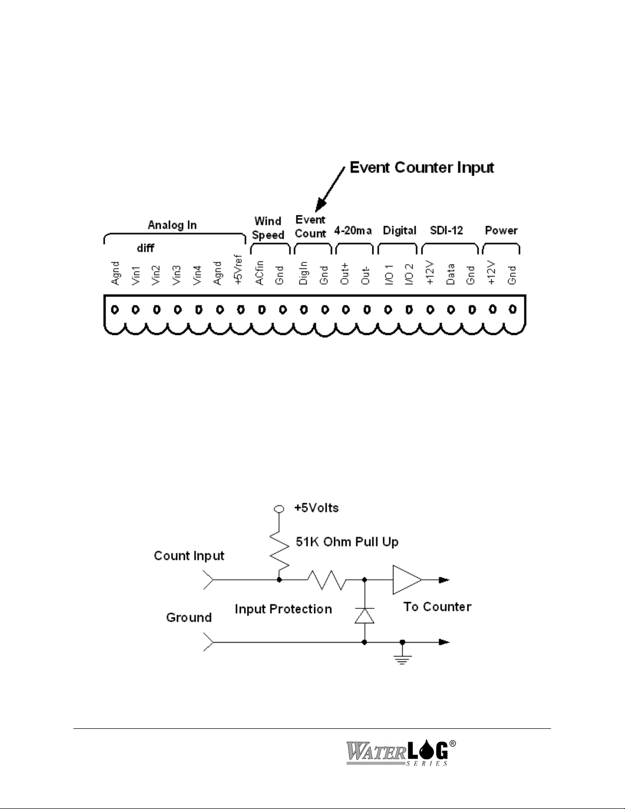
2.2.10 Event Counter Input
Pins 10 and 11 of the terminal block provide connection points for the digital event counter
input.
Figure 2-8 Event Counter Input
This input is normally used with a tipping bucket rain gauge. However, it can be used for other
counter type of applications also. Transient protection is provided for this input to prevent
damage from static discharge or over voltage conditions. This input is pulled high through a 51K
Ohm resistor allowing a switch closure to ground to activate the counter. Figure 2-9 shows a
simplified circuit for this input.
Figure 2-9 Event Counter Circuit
2-10 Hardware Options and Installation XL™ Series

2.2.11 4 to 20 Milliamp Output
Pins 12 and 13 of the terminal block provide connection points for the 4 to 20 milliamp output
signal.
Figure 2-10 4 to 20mA Output Section
Several instrumentation applications use sensors that provide an industry standard 4 to 20
milliamp output signal. The XL™ Series data logger / DCP can output a 4 to 20 milliamp signal
based on any of its inputs. For example, a user may want to connect a temperature probe to the
XL™ and convert the temperature value into a 4 to 20 milliamp output. A temperature probe on
Analog Channel 1 that produces a 0 to 5 volt output representing 0 to 100 degrees Celsius could
easily be setup to produce a 4 to 20 milliamp output that represents the 0 to 100 degrees. The
XL™ does not actually output a 4 to 20 milliamp signal, but rather controls the current in a loop
that is powered externally. Figure 2-11 shows a basic connection diagram.
Figure 2-11 Basic 4-20 mA Wiring Configuration
XL™ Series Hardware Options and Installation 2-11
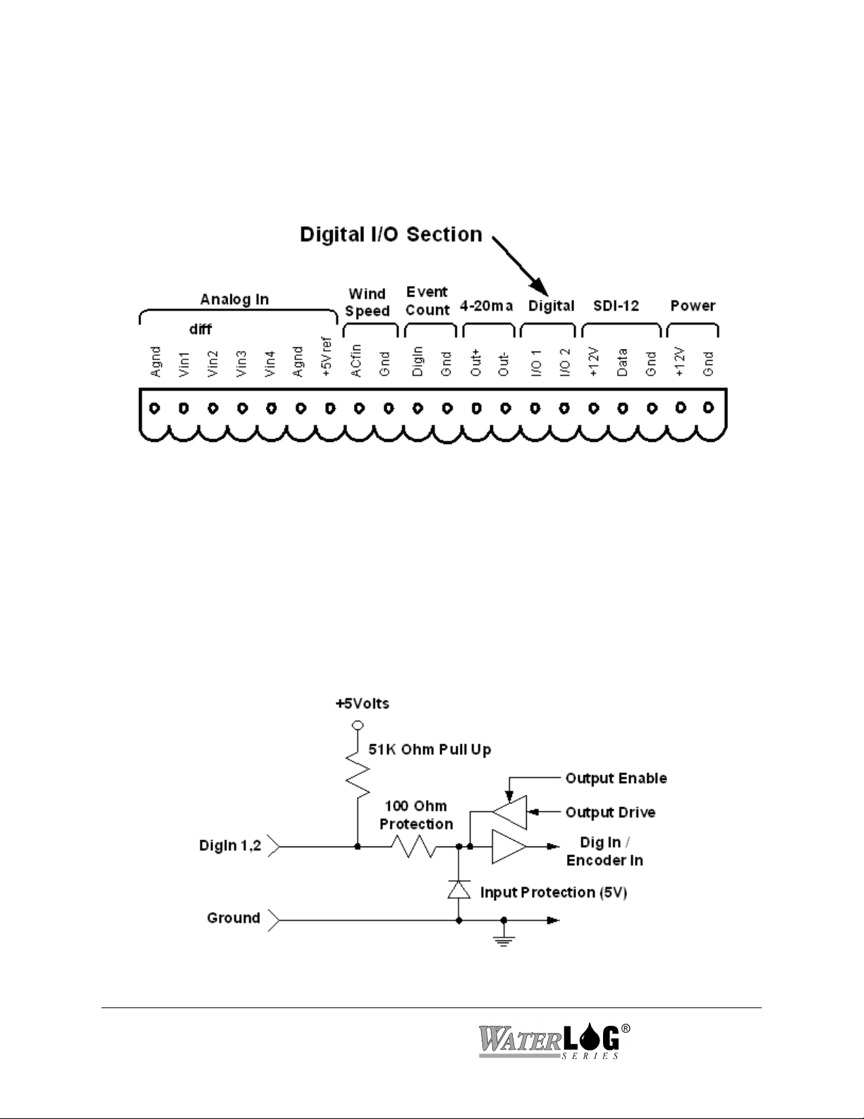
2.2.12 Digital I/O 1 and 2
Pins 14 and 15 of the terminal block provide connection points for the two digital I/O signals.
Notice there is no specific ground point for these signals. Use the digital ground pin of the event
counter or the SDI-12 ground. Do not use the analog grounds.
Figure 2-12 Digital I/O Section
The two digital I/O signals can be configured independently as inputs or as outputs. In the input
mode, the signal has an internal pull up resistor of 51K Ohms. This allows a switch closure to
ground to activate the input. It can also be driven using normal logic levels. As an output, the
drive capability is limited by a 100 Ohm protection resistor. The output will still be about 4.0
volts with a 10.0 mA or less load. When both pins are configured as inputs, they may be used as
a quadrature shaft encoder input. The two digital signals can also be used to simulate a
quadrature shaft encoder. Figure 2-13 shows a simplified schematic of how these pins are
configured.
Figure 2-13 Basic Digital I/O Schematic
2-12 Hardware Options and Installation XL™ Series

2.2.13 SDI-12 Section
Pins 16, 17, and 18 of the terminal block provide connection points for SDI-12 senors and data
loggers. The XL™ can be used as both an SDI-12 sensor and as an SDI-12 data logger. In either
case these connections are made at the same place. The +12V power connection under the SDI12 section is limited to about one amp so it may be necessary to connect the SDI-12 sensor power
line directly to the battery or to main power.
Figure 2-14 SDI-12 Section
If several SDI-12 sensors are to be connected to the XL™, it may be necessary to use an external
terminal strip to provide enough connection points.
Figure 2-15 SDI-12 Expanded Connector System
XL™ Series Hardware Options and Installation 2-13

2.2.14 Power Connections
The last two pins at the far right of the terminal block provide the main connection points for
system power and ground.
Figure 2-16 Main Power Connection Point
Note: When connecting to or removing the wires from these connection points, it is important
to remove the terminal block from the XL™ first, or to have the other end of the wires
disconnected from the battery. This helps prevent loose wires with live voltages
accidently come in contact with other I/O connection points.
2.3 Testing the Installation
After hooking up the battery, the Power light should begin flashing every 5 to 10 seconds. This
indicates that the battery is providing 10 volts or more to the XL™. Press the display On/Off
button and the display should come on, indicating the instrument is functional and ready to use.
You will find detailed user setup information and menu options that will allow complete test and
verification of all sensor connections and operation in the next two chapters.
2-14 Hardware Options and Installation XL™ Series
2.4 Hardware Revision Detection
As the XL series data logger has continued to evolve, changes and enhancements involve both
the hardware and the firmware. The following list shows some of the major changes to the
hardware and how to check as a user what revisions may affect you. For example if your
application requires the +12Volt excitation to be switchable, then you must use board revision
3.1 or newer. The firmware can detect the board revision and if an old board is detected, then the
menu option to set the +12Volt excitation mode will not be displayed because it has no affect.
The table below shows the changes to the hardware over the life of the product.
Board
Revision
Rev 2.1 - Original board
Rev 2.2 - New Power down sequence from normal mode to low power mode.
Rev 3.1 - New 24 bit A to D converter for the generic analog inputs and stage sensor.
Rev 3.3 - A new 16 bit DAC is now used for the 4 to 20 milliamp output option. The
Description
This change will not affect the user operation.
The older boards used a 16 bit A to D converter.
- Added differential mode to analog inputs 1 and 2.
- 500 millivolt range added to all generic analog inputs.
- The 12 volt excitation is able to be turned on and off.
- Able to use higher baud rates on the serial ports, now up to 115200 baud. The
older board would only go to 19200.
older boards used a 12 bit DAC.
- A new internal comm port for H-522 and H-522Plus is used for the built in
GOES radio. This allows com port 2 on the H-522 and H-522 Plus to still be
used for other purposes.
From the built in keypad / display interface the user can see what board revision is in use. Under
the ‘System Status’ menu is a status screen that will show the board revision, for example:
Hardware Rev = 3.1
XL™ Series Hardware Options and Installation 2-15

2-16 Hardware Options and Installation XL™ Series

Chapter 3
Using The Built In Keypad / Display
3.1 Overview
The XL™ series of data loggers is easy to set up and operate. The built-in display and keypad
allow you to view and edit all of the configuration options. This chapter focuses on the operation
of the built-in display and keypad. With a built-in keypad and display there is little need for
external programming devices such as a laptop computer, but remote operations are supported as
explained in chapter 4.
Note: The H-522 has no built in keypad / display, therefore options in this chapter will not apply
to the H-522.
3.2 Keypad/Display Operation (Not available with model H-522)
The XL™ can be fully configured using the built-in keypad and display. The user can easily
move through the different menus using the arrow keys. Changes are made using the ENTER key
and the arrow keys. Most configuration changes are made from a pick list of valid options. Figure
3-1 shows an illustration of the XL™ keypad and display.
Figure 3-1 The XL™ Keypad and Display (Not available with model
H-522)
XL™ Series Using The Built In Keypad / Display 3-1

BATTERY INDICATOR / MONITOR LED or POWER LED
The Power light flashes on and off to show that the XL™ is receiving proper +12V
power. If the power source has failed or provides less than +10V, the power light will
stop flashing. This is a visual indication that the system battery is low.
ERROR LED
The Error light is not used at this time.
MEMORY CARD SLOT
The memory card slot accepts an industry standard ATA PCMCIA FLASH Memory
Card. When operated as a data logger, the XL™ stores the data internally in non-volatile
memory. The data can be transferred from the internal memory to an ATA FLASH
Memory Card for use in computers that have PCMCIA support. Most laptop PC’s have
PCMCIA support built into them, and desktop PC’s can be equipped with PCMCIA card
readers. PCMCIA card readers are available at most PC outlets or from Design Analysis.
All XL™ firmware updates are uploaded from an ATA FLASH Memory Card using this
memory card slot
.
ON / OFF Key
The ON/OFF key is used to turn the display on and off. This key will only turn the
display off from the top level of the menu system. If the unit is on and in a submenu, this
key, much like the CANCEL key, will cause the system to return to the previous menu
screen in the menu system hierarchy until the HOME menu screen is displayed, at which
time pressing the ON/OFF key will turn the display off.
Note: If the unit does not respond to a key press, it may be in the process of measuring.
Wait a few seconds and try again.
To save power, the XL™ display will turn off automatically after five minutes of
inactivity.
ENTER Key
The ENTER key has four functions:
I. Pressing the ENTER key while displaying a status screen such as “Stage = 2.45”
or “PtTemp = 23.65” will cause the H-350XL™ model to make a new
measurement of the selected input and update the screen with the new reading.
II. The ENTER key acts as a “YES” key on screens that are looking for a yes or no
response. For example, pressing the ENTER key on the “Erase Data ?” screen will
cause the erase process to start, but pressing the CANCEL key will abort the
option.
III. The ENTER key starts the editing process for fields that can be modified or
3-2 Using The Built In Keypad / Display XL™ Series

changed. These fields are surrounded by brackets such as [Option] . For example,
the option “Logging [Off]” can be changed to “On” by pressing the ENTER key to
start the editing process, and the text between the brackets starts to flash. In this
case the “Off” flashes and the UP and DOWN arrow keys are used to select the
“On” option, and the ENTER key is used to accept the change.
IV. The ENTER key is used to accept edits or changes. For instance, if you changed
the option “Stage Units [Feet ]” to “Stage Units [Meters],” you would press the
ENTER key to accept the change and the selection would stop flashing.
CANCEL Key
The CANCEL key has three main functions:
I. The CANCEL key is similar to the Escape key on your computer. For example, if
you are editing an option and decide not to make a change, pressing the CANCEL
key will abort the change.
II. The CANCEL key also works as a “HOME” key. If you are in a sub-menu and
wish to return to the previous menu, press the CANCEL key. Pressing the
CANCEL key several times will always take you to the beginning menu screen.
III. The CANCEL key acts as a “NO” key on screens looking for a yes or no response.
For example, pressing the CANCEL key on the “Erase Data?” screen will abort
the option.
Arrow Keys
The UP, DOWN, LEFT, and RIGHT arrow keys have the following functions:
I. The UP and DOWN arrow keys enable you to scroll from one menu to another.
When you reach the bottom screen, the DOWN arrow key will no longer work.
When you are at the top screen, the UP arrow key will no longer work.
II. When moving through the menus, the LEFT and RIGHT arrow keys allow you to
move into and out of sub menus. Screens that have an arrow (->) on the right side
of the display have associated sub menus.
III. The LEFT and RIGHT arrow keys let you move the cursor back and forth across
the field when editing a numerical value such as the slope or the offset. The digit
or blank space will flash to let you know the location of the cursor within the
field. When editing numerical or character options, the UP and DOWN arrow
keys let you move through the list of valid characters or options.
IV. The UP and DOWN arrow keys enable you to scroll through the options within a
menu. For example, if you want to change the XL™ logging option from [Off] to
XL™ Series Using The Built In Keypad / Display 3-3

[On], start the editing process by pressing the ENTER key, and then use the UP
and DOWN arrow keys to choose the desired option. Once the desired option is
selected, pressing the ENTER key will accept the change and the new option will
be displayed.
DECIMAL (or Dot) Key
When editing an option screen with a pick list of valid options, the DECIMAL key lets
you toggle between the first and last option in the list. This is very useful when you want
to select an option near the bottom of a large list.
When first turned on and a status screen is displayed, pressing the DECIMAL key will
cause the menu system to skip all the status screens and move directly to the first menu
item past the status screens. This is handy of several status screens are used.
DISPLAY
The 1 line by 20 character display is used to view and edit all of the menu items. Each
screen represents a unique menu item or system option. There are four types of menu
screens: status screens, sub menu header screens, option screens, and table screens.
STATUS SCREENS
Status screens are normally used to display system information or sensor values. The user
can select what values or information is used for status screens. The system will
automatically update some status screens, such as the battery voltage. As the battery
voltage level goes up and down the displayed value will go up and down automatically.
BATT = 13.2 Volts
There are a few status screens the user can have the system update. A screen that shows
the stage value may be displaying a value that was measured several minutes earlier.
Pressing the ENTER key will cause the system to take a new measurement and display
the new value. When the ENTER key is first pressed the display will show the following
screen indicating the ENTER key was acknowledged, and a measurement is in process.
Scanning...
The updated status value will be redisplayed once the measurement is complete.
Stage = 34.56
3-4 Using The Built In Keypad / Display XL™ Series

SUB MENU HEADER SCREENS
Screens that have an arrow (->) on the right side are classified as sub menu header
screens. The sub menu may be entered by pressing the RIGHT arrow key. There may be
several levels in a sub menu, and each sub menu relates to the header screen text. For
example, the sub menu options of the main menu header screen “Scan Setup” relate to the
scanning process.
Scan Setup -> Scanning [Off]
Scan Rate [HH:MM:SS]
Next Scan = HH:MM:SS
Nxt Scn At[HH:MM:SS]
OPTION SCREENS
Screens with brackets surrounding a system option ( [Option] ) are called option screens.
The user can edit or change the option which will always be shown between the brackets.
In some cases, the option inside the brackets may include several characters, but the
editing process will only change one character at a time, such as with the time or the date
value.
Time [12:34:42]
Pressing the ENTER key will start the editing process, and one of the characters in the
brackets will begin to blink. The UP and DOWN arrow keys are used to change the
blinking character, and the LEFT and RIGHT arrow keys are used to move to the next
character. Pressing the ENTER key will accept the new value, or pressing the CANCEL
key will keep the original value.
On some option screens, all of the text between the brackets will flash when the option is
to be edited. The UP and DOWN arrow keys are used to select a valid option from a list
specific for that option.
Baud Rate [9600]
Pressing the ENTER key will start the editing process and the text “9600” will start
blinking. Use the UP and DOWN arrow keys to change between valid choices of 19200,
9600, 4800, 2400, 1200 or 300 baud, or use the DECIMAL key to toggle between the first
and last option of the list. Press the ENTER key to accept the new value or the CANCEL
key to stay with the original value. For these type of options, invalid entries are not
possible.
XL™ Series Using The Built In Keypad / Display 3-5

TABLE SCREENS
Complex screens that look like both option screens and sub menu header screens are
called table screens. The following table shows the menus used to define the logging
report options.
Source 1 [Date ] -> Source 2 [Time ] -> ... Source 25 [None ]
Header 1[ ] -> Header 2[ ] -> ... Header25[ ]
Log Rate 1[00:15:00]-> Log Rate 2[00:15:00]-> ... Log Rate25[00:15:00]
Digits 1 [2] -> Digits 2 [2] -> ... Digits 25 [2]
Col 1 Fn()[NOW ] -> Col 2 Fn()[NOW ] -> ... Col 25 Fn()[NOW ]
Stat Scrn 01 [No ] -> Stat Scrn 02 [No ] -> ... Stat Scrn 25 [No ]
The LEFT and RIGHT arrow keys let you to move through the table horizontally, and the
UP and DOWN arrow keys let you to move through the table vertically. While moving
through a table, pressing the CANCEL key will take the system back to the sub menu
header screen used to enter the table. Options in the table may be edited as previously
explained.
3.3 Familiarization
The best way to become familiar with the system is to explore the system options and features.
Turn the unit on, move through the menus, and make changes to some of options in order to
experiment with the system. Do not worry about mis-programming the unit, the “Reset Defaults”
option will change the unit back to the factory settings.
3-6 Using The Built In Keypad / Display XL™ Series

3.4 Main Menu Description
The tables on the following pages show the main menu structure of the XL™. The main menu
includes status screens, which allow the user a quick view at sensor data, and sub menu header
screens that separate the main configuration options of the XL™ into there respective sections.
Stage = X.XX
PtTemp= XX.XX
BATT = XX.XX
Sensor Input Setup->
Output Options ->
Data Options ->
Scan Setup ->
System Setup ->
System Status ->
Accessory Setup ->
Stage = X.XX
PtTemp= XX.XX
BATT = XX.XX
Sensor Input Setup->
Output Options ->
Data Options ->
This table represents the main menu of the XL™ Series DCP. The
user can easily move through the menu using the UP and DOWN
arrow keys. Pressing the CANCEL key repeatedly will cause the
system to return to the top of this menu structure.
Menu items with the pointer (->) on the right side of the screen
have a sub menu related to the displayed menu. Use the RIGHT
arrow key to enter the sub menu.
Use the CANCEL key or the LEFT arrow key to return from the
sub menu to the header screen in the main menu.
The shaded screen on the left is a user definable status screen
³
showing the last measured stage value. When the display is
turned on, this screen will be displayed (unless the user
changes or disables the status screens). This screen is also
considered the “HOME” position, as pressing the
CANCEL key several times will always cause the system to
return here.
Scan Setup ->
System Setup ->
System Status ->
Accessory Setup ->
XL™ Series Using The Built In Keypad / Display 3-7

Stage = X.XX
PtTemp= XX.XX
BATT = XX.XX
Sensor Input Setup->
The 25 log columns can be enabled as status screens. The
³
user defined header text is the label used for the status screen.
³
The default status screens the H-350XL report the last
measured stage value, the last measured internal system
³
temperature, and the current battery voltage. The other status
screens are initially disabled.
Output Options ->
Data Options ->
Scan Setup ->
System Setup ->
System Status ->
Accessory Setup ->
Stage = X.XX
PtTemp= XX.XX
BATT = XX.XX
Sensor Input Setup->
Output Options ->
Data Options ->
Scan Setup ->
System Setup ->
Note: Depending on the XL™ Series Model the status
screens by default will be different from each other. All the
XL™ Series DCP’s are programmable to use or disable the
status screens.
Status screens are enabled or disabled in the logging options
table, see chapter 15.
The “Sensor Input Setup” screen is a sub menu header screen
as indicated by the arrow (->). Pressing the RIGHT arrow
key will cause the system to enter into the sub menu for all of
the sensor input setup options of the XL™.
³
For example in the H-350XL™ model this menu would
include defining how the pressure sensor will be used to
calculate the stage value and defining how the temperature
sensor will report its results. This menu also is used for
defining the generic analog inputs, the counter input, etc.
System Status ->
Accessory Setup ->
3-8 Using The Built In Keypad / Display XL™ Series

Stage = X.XX
PtTemp= XX.XX
BATT = XX.XX
Sensor Input Setup->
Output Options ->
Data Options ->
Scan Setup ->
System Setup ->
System Status ->
Accessory Setup ->
Stage = X.XX
PtTemp= XX.XX
BATT = XX.XX
Sensor Input Setup->
Output Options ->
Data Options ->
Scan Setup ->
System Setup ->
The “Output Options” screen is a sub menu header screen.
The sub menu options allow the user to indicate what to do
with the data once it has been measured. The data can be
³
saved to internal memory, sent to a GOES transmitter, sent
to a printer or terminal through the serial port, or converted
to a 4 to 20 mA signal and sent to other types of control
equipment. Some of the options here are complex enough
that they are described in a separate chapters dedicated to the
application.
The “Data Options” screen is a sub menu header screen. The
sub menu options allow the user to erase data, copy data to
an external data card, view the data file, and see how many
³
free bytes are still left in data memory or on the data card.
For more information refer to the Data Options chapter.
System Status ->
Accessory Setup ->
XL™ Series Using The Built In Keypad / Display 3-9

Stage = X.XX
PtTemp= XX.XX
BATT = XX.XX
Sensor Input Setup->
Output Options ->
Data Options ->
Scan Setup ->
System Setup ->
System Status ->
Accessory Setup ->
Stage = X.XX
PtTemp= XX.XX
BATT = XX.XX
Sensor Input Setup->
Output Options ->
The “Scan Setup” screen is a sub menu header screen. The
sub menu options allow the user to enable and disable
scanning and define how often to scan the connected sensors.
NOTE: Scanning is the heart of the system. All major
operations are based on scanning being enabled. Logging,
³
GOES radio operations, ALERT radio operations, and
several other options will only happen if scanning is enabled.
Data Options ->
Scan Setup ->
System Setup ->
System Status ->
Accessory Setup ->
The “System Setup” screen is a sub menu header screen. The
sub menu options under this heading are used to define
³
generic system options such as the time of day, date, serial
port settings, etc.
3-10 Using The Built In Keypad / Display XL™ Series

Stage = X.XX
PtTemp= XX.XX
BATT = XX.XX
Sensor Input Setup->
Output Options ->
Data Options ->
Scan Setup ->
System Setup ->
System Status ->
Accessory Setup ->
Stage = X.XX
PtTemp= XX.XX
BATT = XX.XX
Sensor Input Setup->
The “System Status” screen is a sub menu header screen. The
sub menu options under this heading are used to view how
the system is operating; if there have been any unexpected
³
power resets, battery voltage levels, etc.
Output Options ->
Data Options ->
Scan Setup ->
System Setup ->
System Status ->
Accessory Setup ->
The “Accessory Setup” screen is a sub menu header screen.
The sub menu options under this header allow the user to
control accessory products connected to the XL™ such as the
H-355 Bubbler system. The H-355 bubbler is discussed in a
separate chapter.
³
XL™ Series Using The Built In Keypad / Display 3-11

3-12 Using The Built In Keypad / Display XL™ Series

Chapter 4
PC Menu Interface Operation
4.1 PC Menu Interface
All remote communications with the XL™ are through a command interface or menu interface
using the first RS-232 Serial Port. Note: A NULL modem connector must be used between the
PC and the XL™ for direct connections. If in the command mode, the command “MENU” is
used to start up the menu interface allowing simple human access to the system options. To
access the command or menu interface, the XL™ must be connected to a computer that is
running some type of terminal emulation program. The terminal emulation program must use the
same communication settings as used by the XL™. The default XL™ communication settings
are shown below along with other valid options.
COMMUNICATION
SETTING
BAUD RATE:
DATA BITS:
STOP BITS:
PARITY:
DUPLEX:
TERMINAL
EMULATION:
FLOW CONTROL:
STARTUP MODE:
Basically all options available through the menu interface are also available using the command
interface or the built in keyboard and display. This chapter focuses only on the remote menu
interface.
DEFAULT XL™
SETTING
9600
8
1
None
Full
VT-100, (VT-52 on
older firmware
versions)
Software (Xon / Xoff)
Menu Mode (SW Rev
2.04) (Command mode
on older Versions)
OTHER XL™ OPTIONS
300 to 19200 on hardware Rev A to
M 300 to 115200 on hardware Rev
N up.
None
None
None
None
VT-52, VT-100
None or Hardware
Command Mode, Menu Mode
When the computer is connected (direct connection or modem connection), pressing any key will
wake up the XL. If the XL is set to startup in menu mode then the main menu will be displayed.
If the startup mode is set to command mode, then pressing the ENTER key a few times will
cause the command interface prompt to be displayed. This prompt appears as an arrow “->” on
the left side of the screen. It may take a few key presses to “wake up” the XL™ and display this
prompt. Once the prompt is displayed, the XL™ is ready to receive commands. If no commands
are received in a five minute time period, the XL™ will turn off automatically and return to a low
power mode. Enter the command “MENU” at the prompt to access the menu interface.
XL™ Series PC Menu Interface Operation 4-1

4.2 PC Menu General Operations
Each menu option is preceded with a letter or number that when pressed will activate the
indicated option. The ENTER key does not have to be pressed after an option key is pressed.
Some options will open a sub menu and others will allow the user to set or change a system
parameter. When in a sub menu, pressing the ESC key will back up one menu. At the main menu
the ESC key has no effect. Pressing the ENTER key or SPACE bar at any time will refresh the
current screen.
At the bottom of each menu screen is an “Enter Option >” prompt. When an option key is
pressed that allows a system parameter to be changed, any additional information for that option
will be displayed after the prompt. There are two types of system parameter change options, first
is an option that requires direct keyboard input like a file name or a column header label. The
second is an option that has a pick list of valid options such as an input source option. This type
of option allows the user to scroll through the valid options using UP and DOWN arrow keys.
Pressing the ENTER key will select the option that is visible.
4-2 PC Menu Interface Operation XL™ Series

4.3 Main Menu Screen
The following shows what the “Main Menu” screen looks like. This may also include a user
defined ‘welcome message’ on the top line of the display. The product here is shown as an H350 XL but could be any of the XL series of products.
H-350 XL Main Menu
V - View Status
I - Sensor Input Options
D - Data Options
O - Output Options
S - Scan Options
C - Configure System
A - Accessory Setup
E - Enter Command Mode
X - Exit
Enter Option >
Each option in the main menu is a link to a submenu. Each section will be described in detail in
a later chapter dealing with the specific menu items.
V - View status: Displays the main system status information.
I - Sensor Input Options: Used to configure the sensor input parameters such as slopes and
offsets for the analog inputs, configure the Digital I/O modes, and
SDI-12 sensor configuration.
D - Data Options: Allows the user to retrieve data from the unit, erase data from
memory and perform other internal data and card operations.
O - Output Options: Defines if and how the data is stored internaly, transmitted via
GOES or displayed on remote displays, etc.
S - Scan Options: Defines when and how often the unit scans the sensors, and
performs data output operations.
C - Configure System: Used to set basic system options such as time and date, site ID,
serial port options and other system level options.
A - Accessory Setup: Configures system accessories such as the H-355 bubbler.
E - Enter Command Mode Exit the menu mode and enter the command mode immediately.
X - Exit Exit the menu mode and return to the low power sleep mode.
XL™ Series PC Menu Interface Operation 4-3

4-4 PC Menu Interface Operation XL™ Series
Chapter 5
Miscellaneous System Setup
5.1 Overview
The following menu structure represents all the sub menus under the “System Setup” header.
General system options unrelated to input options or output options are normally found here.
These options include setting the time and date, and defining a name for the site. Other options
for saving and retrieving setup information or resetting the system to factory defaults are also
found here.
Several of the options under this menu are big or complex enough that they are explained in their
own chapter.
5.2 System Setup
Built in Menu Structure: System Setup Options Menu.
The order of options in the built in menu differs slightly than that of the PC menu options. The
text below will follow the order of the PC menu.
System Setup -> Time [HH:MM:SS]
Date [MM/DD/YY]
Date Fmt [MM/DD/YY]
Sync [Sync Disabled]
Sync Time Now?
Last Synced On DD/MM
Site ID [Site_ID ]
Advanced Options -> == See Section 5.4==
Serial Port Setup -> == See Chapter 6 ==
SDI12 Sensor Setup-> == See Chapter 14 ==
SDI12 Logger Setup-> == See Chapter 14 ==
System Config Opts-> == See Chapter 7 ==
Functions Options-> == See Chapter 21 ==
XL-Basic Options-> == See Chapter 22 ==
Update Firmware?
XL™ Series Miscellaneous system Setup 5-1

PC Menu Screen: System Setup Options.
System Setup (Esc to Return)
T - Time: HH:MM:SS
D - Date: MM/DD/YY
E - Date Fmt:MM/DD/YY
I - Site ID: Site_ID
A - Advanced Setup Options
M - SDI Sensor Mode Setup (See chapter 14)
L - SDI Logger Mode Setup (See Chapter 14)
P - Port Setup (See Chapter 6)
C - Configuration Files (See Chapter 7)
R - Reset Defaults (See Chapter 7)
G - Sync Time Options
F - Functions Menu (See Chapter 21)
B - XL-Basic Code Menu (See Chapter 22)
U - Update Firmware
Enter Option >
PC Interface View Built In Display Screen
T - Time: HH:MM:SS
Time [HH:MM:SS]
This option is used to check or set the time clock used by the data logger. This is normally set to
local time or to international standard time. This is the time used to tag each scan placed in the
data file. This is a different time clock the one in the GOES radio. The GOES radio time clock
is normally set automatically by a GPS system and must be set to international standard time.
The display will be updated each second to allow easy viewing of the current time.
PC Interface View Built In Display Screen
D - Date: MM/DD/YY
Date [MM/DD/YY]
This option is used to view or set the system date. The default format is MM/DD/YY, but it may
be changed using the date format option if needed.
PC Interface View Built In Display Screen
E - Date Fmt: MM/DD/YY
Date [MM/DD/YY]
This option is used to set the date format. The default format is MM/DD/YY, but it may be
changed to other formats such as DD/MM/YY, YY/MM/DD, or DD/MM/YYYY. This format
will be used when the date is logged to the data file.
5-2 Miscellaneous System Setup XL™ Series

PC Interface View Built In Display Screen
I - Site ID: Site_ID
This option allows the user to enter in an eight character label that defines the site. This will also
be used as the filename for data files and other files related to this site. A file extension will be
added automatically when the file is created. Data files will have a numerical extension such as
.000 .001 or .002 and so on up to .099. Configuration files will have a .CFG extension. A
system log file will have a .LOG extension. Other file types will also exist using this variable as
the file name.
Note: Since the ‘Site ID’ variable is used as a file name, it must not contain any imbedded
blanks or wildcard characters (*) and must be left justified, in other words it must be a DOS
compatible filename. Valid site ID labels may include letter, numbers, or the underscore. Spaces
are not valid characters for the site ID as they will cause an error and may prevent a file from
being opened.
PC Interface View Built In Display Screen
U - Update Firmware?
Site ID [Site_ID ]
Update Firmware
This option is used to update the operating system firmware. As new versions of software are
produced, they will be placed on the web at www.waterlog.com. Users can download new or
even older versions of the software. The file will be a ZIP file that normally will contain two
files, first is a bin file that is the new firmware, and the second is a PDF or text file that will have
documentation on it related to the changes in the firmware. The user should read the PDF file to
make sure they understand the changes in the newer version of firmware. There may be no
reason to update a unit if the new changes are not needed. It is not necessary to update every
time a new version is released, however it is best not to let too many versions go by without
updating. Each release may also fix small problems in the code that may or may not be listed in
the update documentation. Also it is easier for the customer service group to help out on the
newer versions of firmware. Here is a step by step list of the update process.
1 - The user downloads a zip file from the web page.
2 - Unzip the files and read the update overview file to see if the new options are needed or
not.
3 - Load the bin file onto an ATA data card and insert the card into the XL.
Note: Do not put the zip file on the data card.
4 - Start the update process using the “Update Firmware” option as shown above.
XL™ Series Miscellaneous system Setup 5-3

5 - The XL will save a configuration file on the internal data card called update.cfg. Then
the XL will list the files on the ATA card and allows the user to use the Up and Down
arrow keys to select the desired bin file. Press the ENTER key to accept the selected file.
6 - The XL will erase the main program memory and then loads in the new firmware.
7 - When the new firmware is done loading the XL will initialize new variables. This makes
sure any new variables associated with the new version of firmware is in an acceptable
range. This actually resets every option to the factory default value.
8 - Last of all the XL will reload the update.cfg file to set up the unit as close to the same
mode it was before the update started.
9 - The user should look over the settings to verify they look as expected.
10 - To make sure the new version was loaded correctly and to check the RAM run a
checksum test and make sure it passes and that it indicates the stack is ok. If the
checksum test fails try reloading the firmware again. If the stack is bad then cycle power
to the unit and try the test again.
5-4 Miscellaneous System Setup XL™ Series

5.3 Time Sync Options
The new high data rate GOES Radio operations require very accurate time clocks. In most cases
on board timers are unable to maintain the needed accuracies. In this case the XL™ and the
GOES Radio can be synchronized via a GPS system.
The built in menu structure lists three optional screens for the time sync options but the PC menu
has a separate menu for these same options.
PC Menu Screen: Time Sync Options.
Time Sync Options (Esc to Return)
Last Sync On: 00/00
T - Time: 20:35:54
D - Date: 02/20/03
S - Sync: Sync Disabled
N - Sync Time Now
Enter Option >
PC Interface View Built In Display Screen
Last Synced On: MM/DD
Last Synced On MM/DD
There are several different time sync options and which one to use depends on the type of radio
in use. Refer to the section below ‘S - Sync’ options to see if the time sync options should be
used and how they will behave.
This is normally only used with older GOES radios that did not have GPS capabilities and is not
needed with the newer radios.
This is a status screen used to see when the time clock was last synced. It will show the day and
month only. If it is used, then most cases it will show the current day or one day ago which could
still be within the last 24 hour period. If the date is a few days old then it indicates the system
has not synced for a few days.
If this sync is disabled or the unit has never synced then this will show 00/00.
If the GOES radio has a built in GPS system, then this option is normally disabled and the GOES
radio will still be syncing normally. This is the case with the Signal Engineering SE1200 and
Omnisat radios, and the Microcom radio.
The time sync functionality is normally associated to the GOES radio operation. Keep in mind
when using a Signal Engineering model SE100 or SE300 radio, the system will not stop
transmitting based on no time sync. On a model SE1200 radio it must sync at least once every 7
days or transmissions will be stopped regardless of what baud rate is used.
XL™ Series Miscellaneous system Setup 5-5

PC Interface View Built In Display Screen
T - Time: HH:MM:SS
Time [HH:MM:SS]
On the PC interface, this option is normally only used to see and verify the current time, yet it
can be used to set the time also. Notice it is exactly the same as the time option in the menu one
level up.
On the built in menu the normal “Time” option must be used to see if the time sync is working
correctly.
If the user notices the time is not correct and a valid sync mode is selected, they can use the
“Sync Now” option to cause the unit to sync immediately and use this option to verify it was
successful.
PC Interface View Built In Display Screen
D - Date: MM/DD/YY
Date [MM/DD/YY]
On the PC interface, this option is normally only used to see and verify the current date, yet it can
be used to set the date also. Notice it is exactly the same as the date option in the menu one level
up.
On the built in menu the normal “Date” option must be used to see if the time sync is working
correctly.
PC Interface View Built In Display Screen
S - Sync: Sync Disabled
Sync [Sync Disabled]
The accuracy of the time clock in the XL™ may not be as accurate as needed as it may very a
couple of seconds per day. If a GOES radio is part of the system the XL™ may be synced to the
GOES clock which normally has less drift. It is also possible to sync to a GPS system that will be
very accurate. If the time is synced to the GOES radio or to a GPS system, then the time of the
XL™ will normally be set to international standard time. Valid sync option are as follows:
Sync Disabled: This is the default selection. The data logger will not sync to any time
source. The time and date must be set manually. If the GOES radio is used
and it has GPS options, then the radio may still be syncing to the GPS
system but the logger is not.
5-6 Miscellaneous System Setup XL™ Series

Logger to GPS: This option syncs the logger clock only to the GPS system. In this case the
GPS system must be the H-339 “Time Keeper” from Design Analysis.
This selection will not update a GOES radio. This option is not widely
used.
GOES to GPS: This option syncs the GOES clock only to the GPS. In this case the GPS
system must be the H-339 “Time Keeper” from Design Analysis. This
selection will not update the data logger time clock. This option is
normally only used with older Signal Engineering GOES radios that did
not incorporate a GPS receiver. This could not be used with the Telonic’s
radios.
Both to GPS: This option syncs both the logger clock and the GOES clock to GPS. In
this case the GPS system must be the H-339 “Time Keeper” from Design
Analysis. This option is normally only used with older Signal Engineering
GOES radios that did not incorporate a GPS receiver. This could not be
used with the Telonic’s radios.
Logger to GOES: This option syncs the logger clock to the GOES clock. In this case the
GOES radio may or may not be using a built in GPS system. In any case
the time clock in the GOES radio is more accurate than the logger clock
and in any case this will keep the two clocks the same. This is commonly
used when the GOES radio utilizes a GPS receiver and the user wants to
set the logger to the same time as the GOES radio. This would be
international standard time.
Sync Each Scan: This is a test mode for the H-339 “Time Keeper” used in manufacturing
and design. Normal applications should not use this mode.
When the sync option is selected, the time will be synched according to the option selected once
daily following the first scan after midnight 12:00 AM (00:00:00 GMT).
PC Interface View Built In Display Screen
N - Sync Time Now
This option is used to force the system to sync the time immediately. This is normally used
during an installation of a new site or on a site visit to see if the system is working properly.
Sync Time Now?
XL™ Series Miscellaneous system Setup 5-7

5.4 Advanced System Setup Options
There are a few system options that are used or changed very seldom. Some of these options are
added for very specific applications.
Built in Menu structure: Advanced system Setup Options.
System Setup -> Advanced Options -> SignOn Msg [# ]
Use PassWord [No ]
Password [#123]
Sys TimeOut [300]Sec
AutoOff Enabled
Side Button Setup ->
Excite Warmup [00]Sec
+12VX On [Always ]
User Mode [Normal]
PC Menu Screen: Advanced System Setup Options.
Advanced System Setup Options: (Esc to Return)
W - Welcome Message: #
E - PassWord Enabled: No
P - PassWord: #123
T - System Timeout: 300
A - AutoOff Enabled: Yes
B - Side Button Mode: Hold to Update
U - User Mode: Normal
D - Excitation Delay: 0
S - Switched Excitation On: Always
Enter Option >
PC Interface View Built In Display Screen
W - Welcome Message: #
SignOn Msg [# ]
The welcome or sign on message will be displayed on the top line of the main menu on the PC
interface. On the built in menu it will be the first message displayed when it is turned on. This
can be most any text message up to 20 characters long. If the first character of the sign on
message is ‘#’ then the option is disabled.
5-8 Miscellaneous System Setup XL™ Series

PC Interface View Built In Display Screen
E - PassWord Enabled: No
Use PassWord [No ]
There is a password option for the built in menu that is enabled using this option. When enabled
the status screens will be accessible but any other options will be hidden until a valid password is
entered.
PC Interface View Built In Display Screen
P - PassWord: #123
PassWord [#123]
This option is used to set a password. The “#123" is a default that could be used if the user
defined password is lost.
PC Interface View Built In Display Screen
T - System Timeout: 300
Sys TimeOut [300]Sec
This is a timeout used to turn off the unit if the user leaves it idle. The default is 300 seconds.
This can be set between 15 and 600 seconds.
PC Interface View Built In Display Screen
A - AutoOff Enabled: Yes
AutoOff Enabled
This option is used to enable or disable the auto off feature. There may be a time that the user
needs to keep the display on all the time so they can watch automatic updates of some system
variable. On the built in menu pressing the Enter key will toggle this option.
PC Interface View Built In Display Screen
B - Side Button Mode: Hold To Update
Side Button Setup ->
The side button can be programmed for different functions:
Hold To Update: When the unit is turned off, pressing the side button will turn it on then
displays the value of the first item defined in the log report. Press and
hold the button for a few seconds will cause the current value to be
updated. Pressing the button and quickly releasing it will cause the next
item defined in the log report to be displayed.
XL™ Series Miscellaneous system Setup 5-9

Live Readings: When the unit is turned off, pressing the side button will turn it on and
display the value of the first item defined in the log report. The value will
be updated automatically. Pressing the button causes the next item in the
log report to be displayed. If the current sensor takes a long time to update
such as an SDI12 sensor, then pressing the button may be ignored until the
value is updated.
Run Pgm BASIC1: In this mode pressing the side button causes the unit to execute the
BASIC-1 program.
PC Interface View Built In Display Screen
U - User Mode: Normal
User Mode [Normal]
The user mode option has always been a part of the XL series data loggers but until recent
versions has resided in a hidden menu, only accessible by the manufacture or select customers
that need access to this option. The default setting for this option is ‘NORMAL’ which handles
95% or more of our users. There are a few applications that require special handling. There are
some customers that have bought several hundred units and require a simple user mode for there
organization. For these reasons the user mode option exists. Below is a quick description of the
different user modes.
Normal: This is the most common used mode and used by over 95% of the users. The
manual is also based around this mode.
NOAA: This mode is only used with the H-350XL. This mode is intended for NOAA
when they or one of there contractors is running a PORTS application. NOAA
uses a special measurement algorithm when measuring water levels. This
basically is a 3 minute averaging technic this returns an average, standard
deviation, and number of outliers. This also collects data at a 6 minute rate. In
this mode the GOES data is also formatted based on there requirements. The
GOES format uses binary data with ASCII tags to identify the data. This format
requires special decoding. For complete information on this mode request the
supplement “NOAA GOES Format”. Again, this is only valid on the H-350XL.
LCRA: This mode only applies to the H-350XL. This stands for Lower Colorado River
Authority. In this mode whenever the H-350XL measures the stage, the resulting
value is placed in the SDI-12 buffer so if the H-350XL is used as a sensor
connected to an SDI-12 master, the master can collect the data at any time from
the last measurement simply by issuing the data retrieval command, aD0!.
NIWA: NIWA is the leading provider of Atmospheric and aquatic data and services in
New Zealand. The main difference here is the factory defaults are different than
5-10 Miscellaneous System Setup XL™ Series

when in the normal mode. These options may change from one version to another
based on their desires.
SRP: SRP is Salt River Project, a major water management organization in Arizona that
have bought large quantities of units. In this mode a couple of the menus have
been changed for their needs.
INSAT: This is the mode required when used in India and transmitting data to the Indian
satellite system.
MSATG2: This mode is used for the mid eastern satellite system generation two. The GOES
radio currently manufactured be Signal Engineering can work for this network but
must be set to handle the different frequency range. For more information on this
mode request the supplement “Meteosat Operation”.
MSAT_I: This mode is used to set the GOES radio to use the international frequencies and
is used with the original mid eastern satellite system. The GOES radio currently
manufactured be Signal Engineering can work for this network but must be set to
handle the different frequency range. For more information on this mode request
the supplement “Meteosat Operation”.
FIRELG: This mode is intended for use by the Bureau of Reclamation, forest and range fire
units. When the unit is in this mode and the unit is reset to factory defaults,
several options are set based on their needs and are different from the normal
settings.
PC Interface View Built In Display Screen
D - Excitation Delay: 0
This option is used to delay the actual scan process for xx seconds after the excitations have been
turned on. This is for both the +12 volt and the +5.0 volt excitation. The default is 00 seconds
and it can be as long as 99 seconds. When set to 00 seconds there will still be about a half
second delay in order to allow the excitations to stabilize.
PC Interface View Built In Display Screen
S - Switched Excitation On: Always
This option is used to select when the +12 volt excitation should be turned on. The two options
are “On Always” meaning never turn off. The other option is “On At Scan” meaning only turn
on when the unit turns on to scan. On older hardware this excitation could not be turned off.
This option may not be displayed when this version of firmware is used with older hardware.
Excite Warmup [00]Sec
+12VX On [Always ]
XL™ Series Miscellaneous system Setup 5-11

5-12 Miscellaneous System Setup XL™ Series

Chapter 6
Serial Port Options
6.1 Introduction
The serial port setup options are found under the the “System Setup” or System Configuration”
menu. Since the options for the serial ports are an integral part of the operation of the unit they
will be discussed in their own chapter.
6.2 Serial Port Menus
Built in menu structure: Serial Port Options Menu
System Setup -> Serial Port Setup -> BaudRate Com1 [9600]
BaudRate Com2 [9600]
BaudRate Com3 [9600]
StartUp 1 [Menu Mode]
StartUp 2 [Menu Mode]
StartUp 3 [Menu Mode]
Flow Control [XXX]
Char Delay [XXX]
Line Delay [XXX]
Emulation [XXXXXX]
Quiet Mode [Off]
QuietModeDur[XXX]
XL™ Series Serial Port Options 6-1

PC Menu Screen: Serial Port Options.
Port Setup (Esc to Return)
B - Baud Rate, Com 1: 9600
Com 2: 9600
Com 3: 9600
S - StartUp Mode Com 1: Menu Mode
Com 2: Menu Mode
Com 3: Menu Mode
F - Flow Control: SW
C - Character Delay: 000
L - Line Feed Delay: 000
T - Terminal Emulation: VT-100
Q - Quiet Mode: Off
D - Quiet Mode Duration:015
Enter Option >
PC Interface View Built In Display Screen
B - Baud Rate, Com 1: 9600
BaudRate Com1 [9600]
This option sets the baud rate for the selected serial port. This can be serial port 1, 2 or 3. This is
the baud rate that will be used when the port is used for the menu interface, command mode,
BASIC programs and the auto print functions. There are some processes that use the serial ports
that require a different baud rate and will override this selection. For example the ALERT radio
only functions at 1200 baud, GOES is always 9600, and modbus must be set to 9600 or 19200
baud and is selected under the modbus options menu. Some older modems and some cell phone
modems work best as slower baud rates such as 1200. Valid baud rates are 115000, 57600,
38400, 19200, 9600, 4800, 2400, 1200 and 300. Older units have hardware that only allow baud
rates of 19200 and slower. The default baud rate is 9600 for all three serial ports.
PC Interface View Built In Display Screen
S - Startup Mode Com 1: Menu Mode
Startup 1 [Menu Mode]
This option allows the user to select how the unit will start up when woken up over the serial
port. The default mode is to start up in a menu mode but it may be desired to start in the
command mode. When using the voice modem in the voice mode it must be in the command
mode. Notice the three serial ports may be set up differently from each other as required by the
application. Valid options are:
Menu Mode In this mode, when the unit is woken up by activity on the serial port the menu
will be displayed on the connected PC screen. This is the easiest method to set up
6-2 Serial Port Options XL™ Series

and test the unit. This is the default startup mode.
Cmd N/Echo This is command mode with echo off. This mode is normally used for machine to
machine application. There are no prompts used to indicate the unit is ready.
Pressing the ENTER key three or four times will turn on the echo function and a
prompt will be displayed.
Cmd W/Echo This is command mode with echo on. This is normally used when a user
is hand typing the commands so that they can see what is being sent to the
logger. In this mode a command prompt is displayed indicating the unit is
ready to receive commands. The prompt is a simple arrow pointer “->”.
Network This is a very specialized mode. This is a command mode similar to the
command mode with no echo. The prompt will never be displayed. In this mode
the unit will only respond to commands that are indended for this unit. To isolate
this unit from the others the site ID is used as part of the command and is placed
in brackets. For example:
{site1}time?
This would cause the unit called site1 to respond with its time. Any other unit
would not respond. Now the serial ports are normally used for point to point
communications. In this mode it is point to multipoint or one PC communicating
to two or more XL series data loggers. Normally this mode is only used with an
RS232 radio connected to the serial port and the radio link is what provides or
allows the multipoint functionality.
PC Interface View Built In Display Screen
F - Flow Control: SW
Flow control is used to pace the data through the serial port. It is important not to send data faster
than the receiving system can receive it. There are two types of flow control, software and
hardware flow control.
Software flow control (SW) is also referred to as XON / XOFF. When this is enabled the
receiving system will send a character (XOFF) to the XL™ instructing it to stop sending data
until the receiving system can catch up. At the point the receiving system is ready it will send an
XON to the XL™ indicating it is ready for more data. When software flow control is selected it
will only be used during data transfers, not while navigating through the menus or by other
processes that use the serial ports. Software flow control is the default selection.
NOTE: If using XMODEM protocol for data file transfers, software flow control should not be
Flow Control [SW ]
XL™ Series Serial Port Options 6-3

used as a binary checksum value is calculated for each block of data and transferred with the data
block. If the binary checksum value is the same as an XOFF command, then the system may stop
the data transfer prematurely.
Hardware flow control uses two extra pins on the 9 pin connector. This is ‘Request to Send’
(RTS) and ‘Clear to Send’ (CTS). Normally a PC connected to the XL™ will turn on the CTS
signal when it is ready to communicate and watches the RTS signal before it sends anything to
the XL™. The same type of monitoring will be done by the XL™, It will not send anything to the
PC if CTS is not on and will turn on RTS indicating to the PC it is ready.
NOTE: Hardware flow control should only be enabled on the PC when the XL™ is turned on. If
hardware flow control is enabled on the PC and the XL™ is off, the PC will not be able to turn
on the XL™ because the PC will wait for the RTS signal to go active before sending the wake up
characters, and RTS will only go active when the XL™ is turned on over the serial port.
PC Interface View Built In Display Screen
C - Character Delay: 000
Char Delay [000]
This sets a time delay between transmitted characters in milliseconds. Some modems, normally a
radio modem, may require this type of control in order to pass valid data through the serial port.
When using a modem everything may look fine and then all at once it looks like garbage. This
may be an indication of overflowing a buffer in the modem and it was not able to warn the XL™
soon enough to prevent the problem and the data becomes junk. Try setting the character delay at
005 and then working up as needed. A combination of a character delay and the line delay may
provide the best system operation. The default is 0.
NOTE: This only applies to com port 1 at this time.
PC Interface View Built In Display Screen
L - Line Delay: 000
Line Delay [000]
This is a delay used at the end of each line of data sent out the active serial port. This is in
milliseconds. This used in combination with the character delay may be required by some modem
applications. The default is 0 indicating no delay.
PC Interface View Built In Display Screen
T - Terminal Emulation: VT-100
Emulation [VT-100]
Terminal emulation is used to control computer screen operations like clearing the screen or
6-4 Serial Port Options XL™ Series

moving the curser around to update different portions of the screen without having to redraw the
complete screen. If the information on the screen appears to be from the XL™ but is displayed in
abnormal places or intermixed with abnormal characters, then emulation is the most probable
cause of the problem. The two emulation modes supported are VT-52 and VT-100.
PC Interface View Built In Display Screen
Q - Quiet Mode: Off
This menu option is used to prevent the XL™ from echoing back characters received via the
serial port for a certain duration of time specified in the quiet mode duration option. This option
is helpful in preventing endless echo looping in applications such as communicating with a
modem. The default is off, but if a modem is in use then it may be best to turn this on.
PC Interface View Built In Display Screen
D - Quiet Mode Duration: 015
Quiet Mode [Off]
QuietModeDur [015]
This menu option sets the Quiet mode duration. When the Quiet mode is enabled and the unit is
turned off through the serial port, the unit will not be able to turn back on via the serial port for
this time period. This duration is entered in seconds and the default is 15 seconds.
XL™ Series Serial Port Options 6-5

6.3 Serial Port Hardware Description
The three RS-232 ports are used to connect to a PC, GOES Transmitter, modem, remote display,
or other serial equipment for standard serial communications. These ports are configured as a
DTE type of device. This means they will plug directly into a modem (a DCE type device), but
will require a NULL modem adaptor if connected to a PC (a DTE type device). The NULL
modem cable crosses the communication lines allowing two similar devices to communicate.
Figure 2-5 shows the pin out for all three ports.
Figure 2-5 RS-232 Connector
PIN DIRECTION NAME
1 Input Data Carrier Detect (DCD)
2 Input Receive Data (RD)
3 Output Transmit Data (TD)
4 Output Data Terminal Ready (DTR)
5 Ground (GND)
6 Input Data Set Ready (DSR)
7 Output Request To Send (RTS)
8 Input Clear To Send (CTS)
9 Input Ring Indicator (RI)
6.4 Serial Port Functions
SERIAL PORT PIN-OUT
6-6 Serial Port Options XL™ Series

The XL™ has three com ports that in some cases any com port can be used for a specific
application and in other cases only a specific com port can be used for some functions. For
example one of the uses of the RS-232 port number 3 is for MODBUS. If the user tries to use
MODBUS on any other port but com port 3 it will not work. The following table lists each RS232 port and its usage.
Com Port Function Com 1 Com 2 Com 3 Com 5
Menu Interface (Direct connect)
Command Interface (Direct Connect)
Menu Interface (Modem connection)
Command Interface (Modem Connection)
ALERT Radio
Alarm Call Out (All Modes)
Alarm Call Out (Direct Connect Only)
Modbus
GOES
SDI-12 Secondary Port (Master Mode)
Auto Print
Remote Display (From Menu)
BASIC Print Command
X New New
X New New
X New New
X New New
New X X
X
X
X
X New(1)
X New X
X X X
X X X
X X X
Basic Input Command (Numeric Only)
X = Was functional in older versions of the firmware, (2.09 and older).
New = Now functional in this version of the firmware, (2.10 and newer).
Blank = Not a valid option.
New(1) = Com port 5 is only available on the new hardware (Hardware Version 3.3) and is
only used on the H-522 and H-522 Plus using firmware version 2.10 or newer.
Note: On older hardware, (3.1 and older) the H-522 and H-522Plus have the GOES HDR radio
built into the main box of the unit and internally connect to the RS-232 port number 2. The
connector for this port is still physically placed on the outside of the box but is just there for
mechanical reasons and is not connected internally. On the newer hardware, (3.3 and newer) the
H-522 and H-522 Plus are connected to the new internal com port number 5 and com port 2 is
usable again.
X New X
XL™ Series Serial Port Options 6-7

6-8 Serial Port Options XL™ Series

Chapter 7
System Configuration Files
7.1 Overview
The configuration files allow all the user setup information to be saved to a file and used later for
any reason needed. Once a system is configured it is best to save the setup information so that it
may be retrieved later if the system is replaced or duplicated. For example, when a unit has been
programmed it may be desired to save the user settings to a file so other units may be quickly
programmed the same way and then minor modifications made for site specific needs. The files
can be created on the external data card, or to internal data memory.
7.2 Configuration Files Menus
One of the sub menu structures found under the “System Setup” or “Configure System” menu is
the “Configuration Files” sub menu. These options are used to save and retrieve setup
information, and to reset the unit back to the factory defaults.
Built in Menu Structure: Configuration Files Screens.
System Setup -> System Config Opts-> Copy Setups to Mem ?
Copy Setups to Card?
Load From Memory ?
Load From Card ?
Reset to Defaults ?
PC Menu Screen: Configuration Files.
Configuration Files Menu (Esc to Return)
C - Create CFG File
S - Setup From CFG File
Enter Option >
XL™ Series System Configuration Files 7-1

PC Interface View Built In Display Screen
C - Create CFG File
Copy Setups To Mem ?
When using the PC menu, this option is used to save a configuration file to the internal data
memory or to the external data card. When the option is selected it will prompt the user to select
either the internal data memory or the external data card.
When using the built in menu there are actually two different screens used to save the
configuration file, one for the internal memory as shown above and one for the external data
card. Both options work the same as far as how the file is created, the only difference is the
location of the file saved.
The configuration file is an ASCII text file that may be viewed or printed as a hard copy listing of
the options for the site. Several configuration files can be stored on a single card. The setup
information will be saved in a file with the same file name as the Site ID option and a file
extension of .CFG. This file may be transferred over the serial port using the standard file
transfer options, or copied to the external card using the copy data option.
When the configuration file is saved to the data card can then be removed and placed in a PC and
the file copied to the hard drive or printed for a hard copy of the setup information. Other XL
series loggers can now be programmed the same as the unit that created the configuration file by
using the “Setup From CFG File” or “Load From Memory” options listed below.
PC Interface View Built In Display Screen
S - Setup From CFG File
Load From Memory ?
When using the PC menu, this option is used to select a configuration file from either the internal
data memory or from the external data card. Use the Up and Down arrows on the PC keyboard
to select the desired file and press the Enter key to start the loading or setup process. Once the
setup process is complete the unit will have its user options set based on the contents of the
configuration file.
When using the built in menu there are actually two different screens used to load a configuration
file, one for the internal memory as shown above and one for the external data card. Both
options work the same as far as how the file is retrieved, the only difference is the location of the
file saved. Once the setup process is complete the unit will have its user options set based on the
contents of the configuration file.
7-2 System Configuration Files XL™ Series

PC Interface View Built In Display Screen
R - Reset Defaults
This option is used to reset all of the user options to the factory default values. Be careful using
this option as all setups will be cleared. This will not affect data stored to the FLASH card, nor
the time and date values.
NOTE: This option will not reset the H-355 bubbler options back to its default values.
7.3 Sample Configuration File
Below is a partial listing of a configuration file. The first few lines give some status information
listing the product type and serial number. After the first few lines of status information is the
actual setup information. Each line is actually a command used when the unit is in the command
mode. Therefore any single line could be hand typed into the unit when it is in the command
mode. With close inspection it is possible to relate each command to a user option in the menus.
It is possible to hand edit this file but the entries must be exact and valid options used or the
command will be ignored.
WaterLOG XL Configuration File
H-350 XL
Serial Number = S#001000
Firmware Version = 2.12c
SignOnMessage=#
SystemTimeOut=300
RemoteTimeOut=5
SiteID=Site_ID
UserMode=Normal
Com1BaudRate=9600
Com2BaudRate=9600
Com3BaudRate=9600
FlowControl=SW
TerminalEmulation=VT-100
CharacterDelay=0
LineFeedDelay=0
QuietMode=Off
QuietModeDur=15
DateFormat=MM/DD/YY
SyncTime=Sync Disabled
SDIAddress=0
SDITimeOutValue= 0.00
UserSDITimeRsp=0
SDIMeasurementType0=M
Reset To Defaults?
XL™ Series System Configuration Files 7-3

|
SDIMeasurementType9=M
SDIPort0=SDI-12
|
SDIPort9=SDI-12
SDIRedirect0=0
|
SDIRedirect9=9
SDIParameter1=Stage
SDIDigits1=2
|
SDIParameter9=None
SDIDigits9=2
Plus12VoltExciteOn=Always
ScanRate=00:10:00
ScanOffsetTime=00:00
ExcitationWarmupDelay=0
StageUnits=Feet
StageOffset=0.00
StageAverageTime=1
TemperatureUnits=Deg C
RemStageSource=None
RemStageSlope=1.00
RemStageOffset=0.00
CounterSlope=0.01
SumInterval=Daily
CounterMode=Off
CountRateWindowSize=15
CtrDebounceTime=5
FrequencySlope=1.000
FrequencyOffset=0.000
Analog1Slope=1.00
Analog1Offset=0.00
Analog1Samples=2000
Analog1Range=5.0V
Analog1DiffMode=Off
|
Analog4Slope=1.00
Analog4Offset=0.00
Analog4Samples=2000
Analog4Range=5.0V
Digital1Mode=Digital Input
Digital1PulseLength=1000
7-4 System Configuration Files XL™ Series

Digital1WarmUpDelay=250
Digital2Mode=Digital Input
Digital2PulseLength=1000
Digital2WarmUpDelay=250
EncoderSlope=0.010
EncoderOutSource=None
AutoPrint=Off
RemoteDisplayLabel=Stage =
RemoteDisplaySource=None
RemoteDisplayPort=3
mASource=None
mAMax=20.0000
mAMin=4.0000
VOICEMODEM=Comm-1
VoiceModemSource0=None
|
VoiceModemSource9=None
AlarmsEnabled=No
AlarmRetry=0
Alarm1Source=None
Alarm1Trig=> Set Pt
Alarm1SetPoint=1.000000
Alarm1ResetPoint=0.000000
Alarm1ComMode=Direct
Alarm1Label=Al1
Alarm1Number=
Alarm1SiteNum=0
|
Alarm10Source=None
Alarm10Trig=> Set Pt
Alarm10SetPoint=1.000000
Alarm10ResetPoint=0.000000
Alarm10ComMode=Direct
Alarm10Label=Al0
Alarm10Number=
Alarm10SiteNum=0
ModbusMode=Off
ModbusBaudRate=19200
ModbusParity=Even
ModbusAddress=1
ModbusTimeOut=30
ALERT=Off
ALERTRadioType=H-264
ALERTTxOffsetTime=00:00:00
XL™ Series System Configuration Files 7-5

ALERT1Source=None
ALERT1ID=0000
ALERT1Range=20.47
ALERT1FntType=NOW
ALERT1FixedTxdRate=8 Hours
ALERT1TriggerMode=Off
ALERT1TriggerPoint= 1.000
ALERT1HoldOff=15
ALERT1Override= 2.000
|
ALERT20Source=None
ALERT20ID=0000
ALERT20Range=20.47
ALERT20FntType=NOW
ALERT20FixedTxdRate=8 Hours
ALERT20TriggerMode=Off
ALERT20TriggerPoint= 1.000
ALERT20HoldOff=15
ALERT20Override= 2.000
Logging=On
LogNewFile=None
LogDataFmt=Normal
LogWrap=Disabled
WrapBlocks=255
LogColumn1Source=Date
LogColumn1Header=MM/DD/YY
LogColumn1Rate=00:15:00
LogColumn1Digits=2
LogColumn1Function=NOW
LogColumn1StatScrn=No
|
LogColumn25Source=None
LogColumn25Header=
LogColumn25Rate=00:15:00
LogColumn25Digits=2
LogColumn25Function=NOW
LogColumn25StatScrn=No
GoesRadioType=SE-1200
GoesAddress=00000002
GoesSTBaudRate=100
GoesRRBaudRate=100
GoesSTChannel=000
GoesSTRate=01:00:00
GoesSTOffset=00:00:00
7-6 System Configuration Files XL™ Series

GoesSTWindow=65
GoesCenterData=Yes
GoesSTAppendBattery=No
GoesPreamble=Long
GoesSetupMode=Normal
GoesSTFormat=SHEF
GoesSTOrder=SCAN
GoesSTFirst=Newest
GoesSTSendSHEFCodes=No
GoesSTRedundantDataSets=1
GoesSTColumn1Source=None
GoesSTColumn1SHEFCode=
GoesSTColumn1Rate=00:15:00
GoesSTColumn1Format=XX.XX
GoesSTColumn1BinaryBytes=3
GoesSTColumn1BinaryDigits=2
GoesSTColumn1BinarySigned=Signed Mag.
|
GoesSTColumn20Source=None
GoesSTColumn20SHEFCode=
GoesSTColumn20Rate=00:15:00
GoesSTColumn20Format=XX.XX
GoesSTColumn20BinaryBytes=3
GoesSTColumn20BinaryDigits=2
GoesSTColumn20BinarySigned=Signed Mag.
GoesRRChannel=000
GoesRRRate=00:05:00
GoesRRColumn1Source=None
|
GoesRRColumn5Source=None
AutoPurge=Off
TimedPurge=0
FNT01=0
|
FNT40=0
DIGIOFNT1=0
DIGIOFNT2=0
GOESRTFNT=ana1>100
SideButtonMode=Hold to Update
Com3StartUpMode=Menu Mode
Com2StartUpMode=Menu Mode
Com1StartUpMode=Cmd N/Echo
XL™ Series System Configuration Files 7-7

7-8 System Configuration Files XL™ Series

Chapter 8
System Status Menus / Options
8.1 Status Options Overview
The status screens and options are mainly used to verify the operation and setup of the system.
Many of the screens can be changed based on user settings allowing the user to see what is of
interest to them.
Note: Depending on the XL™ Series in use, the default status screens settings will be slightly
different.
8.2 Status Menus
Built in Menu Structure: Status Screens.
System Status -> Battery = 12.3 Volts
Min Battery = 11.6
Max Battery = 13.7
System Resets = 2
Reset Stat Screens ?
Firmware Ver = X.XXX
Run Checksum Test ?
Hardware Ver = X.X
Serial # = S#XXXXXX
Bubble Line Test?
The options that are in bold are only available using the built in menu.
XL™ Series System Status Menus / Options 8-1

PC Menu Screen: Status Options.
View Status Submenu (Esc to Return)
Time: 09:08:07 Log Source/ Log
Date: 08:27:07 Col# Header Value
Scanning: Off ---- -------- -------Next Scan: 00:06:53 1 MM/DD/YY 08/27/07
GOES Mode: Off 2 HH:MM:SS 09:08:07
FailSafe: OK 3 Stage 7.34
Last GPS Sync: N/A 4 PtTemp 23.52
5 Battery 13.21
Battery: 13.21
Batt Max: 13.64
Batt Min: 12.23
System Resets 000
Site ID: SiteID
Serial #: S#001000
Version: 2.10
C - Checksum Test:
M - Measure
R - Reset Batt Max, Batt Min, & System Resets
Enter Option >
8.3 Status Screen Operations:
PC Interface View Built In Display Screen
Time: 09:08:07 Not Available In This Area Of
The Built In Menu
This is the current system time. Notice this updates every second along with some other values
on the screen. In this menu the time cannot be changed, only viewed.
PC Interface View Built In Display Screen
Date: 08:27:07 Not Available In This Area Of
The Built In Menu
This is the current system date. In this menu the date cannot be changed, only viewed.
8-2 System Status Menus / Options XL™ Series

PC Interface View Built In Display Screen
Scanning: Off Not Available In This Area Of
The Built In Menu
This shows of scanning is turned on or off. This can only be viewed in this menu, not changed.
PC Interface View Built In Display Screen
Next Scan: HH:MM:SS Not Available In This Area Of
The Built In Menu
This is a count down timer until the next scan. If scanning is off then XX:XX:XX is displayed
PC Interface View Built In Display Screen
GOES Mode: Off Not Available In This Area Of
The Built In Menu
This identifies the current GOES Mode of operation. If no GOES radio is connected, N/A will be
displayed.
PC Interface View Built In Display Screen
Fail Safe: Ok Not Available In This Area Of
The Built In Menu
This shows if the fail safe function of the GOES radio is ok or tripped. If it is tripped then the
GOES radio will not transmit and the reset button on the GOES radio must be pressed and held
for a few seconds to reset the radio.
PC Interface View Built In Display Screen
Last GPS Sync: DD/MM/YY Not Available In This Area Of
The Built In Menu
This shows the date of the last GPS time sync. If scanning or GOES is off then N/A is displayed
XL™ Series System Status Menus / Options 8-3

PC Interface View Built In Display Screen
Battery: 13.12
Battery = 13.12 Volts
This screen displays the current voltage on the XL™'s +12V input.
OPERATIONAL NOTE:
The display draws more than 250mA which will pull extra current from the battery and may
cause the reading to be slightly lower than if the battery is measured with a meter while the
display is turned off.
PC Interface View Built In Display Screen
Batt Max: 13.78
Batt Max = 13.78 Volts
Each time the XL™ measures the battery voltage it checks to see if the current voltage is less
than the minimum value detected or greater than the maximum value detected and updates the
min and max values if needed. Note that the battery voltage is not continuously monitored but is
normally only measured once each scan. The battery voltage may briefly rise higher than the
detected max value or drop lower than the min value and still not be detected.
This value is mainly provided as a diagnostic tool to help understand system performance and
reliability. A high value may indicate a faulty regulator. See ‘Reset Status Screens?’ below for
more information.
PC Interface View Built In Display Screen
Batt Min: 12.34
Batt Min = 12.34 Volts
Each time the XL™ measures the battery voltage it checks to see if the current voltage is less
than the minimum value detected or greater than the maximum value detected and updates the
min and max values if needed. Note that the battery voltage is not continuously monitored but is
normally only measured once each scan. The battery voltage may briefly rise higher than the
detected max value or drop lower than the min value and still not be detected.
This value is mainly provided as a diagnostic tool to help understand system performance and
reliability. If the minimum voltage is too low it may indicate that the battery is being
undercharged. See ‘Reset Status Screens?’ below for more information.
When using the built in menu, pressing the ENTER key here will place the unit in a mode that
8-4 System Status Menus / Options XL™ Series

measures the battery at a fast rate allowing it to better detect voltage spikes. The normal battery
monitoring screens measure the battery only a few times per second, but in the fast mode the
battery is measured several times a second allowing it to have a better chance of detecting a
voltage spike. This test is normally used when the battery is in question by entering this mode
and then manually causing the bubbler system to purge which may cause a power surge on the
system. When the bubbler turns on and the battery is weak, the voltage for example may drop
from say 12.5 volts to 9.5 volts very quickly and then level off at 12.0 volts. The low voltage of
9.5 volts in this case may never be detected because it only last for only a few milliseconds, but
can be severe enough to cause undetectable problems such as system resets or missed GOES
transmissions. The screen would have the following message.
Fast Min Mode=XX.XX
PC Interface View Built In Display Screen
System Resets: 002
System Resets = 2
This is a status screen that lists how many times the system has reset. A reset can be caused by
several conditions, low battery and power spikes, power glitches, and power disconnects are the
most common. See ‘Reset Status Screens?’ below for more information.
PC Interface View Built In Display Screen
Site ID: SiteID Not Available In This Area Of
The Built In Menu
This displays the system Site ID. The site ID is also used as the filename for the logged data.
The system uses a DOS file system and since the Site ID text is used as the file name, it must fit
the DOS format for file names. This means no spaces or periods or other non text characters.
PC Interface View Built In Display Screen
Serial #: S#001000
Serial # = S#001000
This shows the instrument serial number. You may be asked to provide a serial number if you
ever call in for technical assistance. This should be the same number as on the serial label on the
side of the unit, yet the label may have worn off, or became hard to read.
XL™ Series System Status Menus / Options 8-5

PC Interface View Built In Display Screen
Version: 2.10
Firmware Ver = 2.10
This is a status screen that displays the current software version of the embedded code. When
calling the factory for assistance the technician may ask what version of code your unit has
installed. This will aid the technician on how to better serve you. Also after doing a field upgrade
it is a good idea to come here and verify the update process was completed as expected.
PC Interface View Built In Display Screen
C - Checksum Test:
Run Checksum Test?
The XL™ can perform a checksum test on the firmware and display a Pass/Fail response. If the
checksum fails, something has corrupted the firmware. In this case, you may need to download
the firmware from a FLASH Memory Card to restore the integrity of the system. This test is
normally used after a system update to make sure the new firmware was loaded correctly and is
running properly. Consult the factory if this test persistently fails.
PC Interface View Built In Display Screen
M - Measure Not Available In Built In Menu
Pressing the M key will cause the XL™ to scan the sensors. The sensor data on the screen will
be updated with the new values, but the data will not be logged to the data card. Some data
values may update automatically.
PC Interface View Built In Display Screen
R - Reset Batt Max, Batt Min, & System Resets
Reset Stat Screens?
This option is used to reset the minimum and maximum battery values to the current battery
value and to reset the system reset counter to 0. The intended use of this option, the battery value
screens and the system reset screens is to provide information on how the system is operating
between field trips. The normal use is to reset the status screens at the end of a field trip, and then
one of the first tasks of the next field trip would be to view these screens to see if any unexpected
conditions occurred since the last trip. Ideally, the number of resets would still be zero and the
max and min battery values would be within a normal operating range. A low minimum battery
8-6 System Status Menus / Options XL™ Series

voltage could indicate a weak charging system, a battery that is too small for the site, or bad
wiring, etc. A low battery could also cause the system to reset. System resets normally indicate a
problem with the battery voltage being too low, bad wiring, or poor power connections.
Lightening and other external factors may also cause the system to reset. A high maximum
battery voltage could indicate that the regulator is bad and that it is passing all of the energy from
the solar panel to the system. The table below summarizes the different conditions and possible
problems.
Battery Condition System Resets Possible Problems Action
Battery Level = Ok
Min Batt Level = Ok
Max Batt Level = Ok
Battery Level = Ok
Min Batt Level = Low
Max Batt Level = Ok
Battery Level = Ok
Min Batt Level = Low
Max Batt Level = Ok
Battery Level = Ok
Min Batt Level = Ok
Max Batt Level = Ok
Battery Level = Ok
Min Batt Level = Ok
Max Batt Level = High
None None, System is operating
normally.
None The minimum battery value
may indicate the charging
system was not operational
for awhile.
Some Low battery caused system
resets.
Some Bad wiring may be causing
problems with power.
None Charging system may be
outputting too much voltage.
None
Make sure the solar panel is
clean. If it is normally cloudy for
several days, may need a bigger
battery, or solar panel.
Make sure the solar panel is
clean. If it is normally cloudy for
several days, may need a bigger
battery, or solar panel.
Check all power wires and
connections for clean and tight
connections, and proper wire
sizes.
Make sure regulator is
functioning properly.
Overcharging the battery will
damage the battery.
PC Interface View Built In Display Screen
Log Source/ Log
Col# Header Value
Not Available In This Area Of
The Built In Menu
---- ----------------- ----------- 1 MM/DD/YY 08/27/07
2 Time 12:23:54
3 Stage 19.32
4 Batt V 12.79
When using the ‘View Status’ option on the PC menu, the middle and right hand side of the
screen will display the last measured data values for each column of the log report options set to
XL™ Series System Status Menus / Options 8-7

log a sensor input. If the column is disable, (column source set to None) then the column
number, header and data will not be listed. The column header text is used to identify the data.
If the column header text is left blank then the text for the column source is displayed to identify
the data. This section of the screen will change greatly based on the user settings, the more
columns enabled the more information will be displayed on the screen.
PC Interface View Built In Display Screen
Not Available Using PC Menu
Hardware Ver = 2.10
As the XL series data logger has continued to evolve, changes and enhancements involve both
the hardware and the firmware. The following list shows some of the major changes to the
hardware and how to check as a user what revisions may affect you. For example if your
application requires the +12Volt excitation to be switchable, then you must use board revision
3.1 or newer. The firmware can detect the board revision and if an old board is detected, then the
menu option to set the +12Volt excitation mode will not be displayed because it has no affect.
The table below shows the changes to the hardware over the life of the product.
Board
Description
Revision
Rev 2.1 - Original board
Rev 2.2 - New Power down sequence from normal mode to low power mode.
This change will not affect the user operation.
Rev 3.1 - New 24 bit A to D converter for the generic analog inputs and stage sensor.
The older boards used a 16 bit A to D converter.
- Added differential mode to analog inputs 1 and 2.
- 500 millivolt range added to all generic analog inputs.
- The 12 volt excitation is able to be turned on and off.
- Able to use higher baud rates on the serial ports, now up to 115200 baud.
Rev 3.3 - A new 16 bit DAC is now used for the 4 to 20 milliamp output option. The
older boards used a 12 bit DAC.
- A new internal comm port for H-522 and H-522Plus is used for the built in
GOES radio. This allows com port 2 on the H-522 and H-522 Plus to still be
used for other purposes.
8-8 System Status Menus / Options XL™ Series

PC Interface View Built In Display Screen
Not Available Using PC Menu
This test is only available on the H-350XL™ Model. This option is used to test the orifice line
for noise and stability. Bubbler line noise can be caused by several conditions, for example, a
loose orifice line that is swaying with the water current, an orifice outlet that has an artificial
pressure or vacuum based on unstable water current, or the bubble growing and releasing, etc.
Press the ENTER key to start the test. The screen will change displaying the following message.
Line Noise = +x.xxxx
When the test is first entered a normal measurement is made and the stage value is saved in two
internal variables called MAX and MIN. Now the difference between the max and min is
displayed. Since the first measurement saves the same value for both the max and min, the
difference is 0.000. The initial measurement takes about 5 seconds as it also compensates for
atmospheric pressure, and A/D offsets. The system then measures the stage repeatedly using the
original atmospheric reading for compensation allowing for a 1 second measurement time. The
MAX and MIN values are updated as new max or min values are detected and the difference
between the MAX and MIN values is displayed on the screen. The difference between the MAX
and MIN will be small and will not increase too much if the line noise is small, but will increase
to a larger number if the line noise is significant. The displayed value is in the same units as set
by the stage ‘Slope’ Coefficient which defaults to feet.
Bubble Line Test?
When installing a new orifice line use this option to test for possible orifice line positions.
Temporarily position the outlet and run this test to see if the position is relatively quiet.
Reposition the line if it is too noisy. After the line is repositioned pressing the Enter key will
cause the H-350XL™ to take a new reference measurement, and start the process again.
Running this test with the orifice line disconnected will show how much noise the H-350XL™
sees internally. This test is used to see if a problem exists with the orifice line or with the H350XL™. This value should be extremely small and is relative to the PSI range of the system in
use. The following table list the approximate resolution for each PSI range and the bubble line
test with the orifice line disconnected should be less than the resolution value. In most cases the
bubble line test will give values less than the resolution even with the orifice line connected in a
good installation.
PSI Range Approximate Resolution
0 to 15 PSI 0.007 Ft
0 to 30 PSI 0.014 Ft
0 to 50 PSI 0.0233 Ft
XL™ Series System Status Menus / Options 8-9

8-10 System Status Menus / Options XL™ Series

Chapter 9
Scanning Options
9.1 Introduction
The scanning options in this menu acts like a master switch for turning off or on all automatic
processes such as logging data and transmitting the data, etc. If scanning is disabled the unit will
still function as a sensor. Options here also are used to set the rate data is collected and
processed.
9.2 Scanning Menus
Built in Menu Structure: Scanning Options Menu.
Scan Setup -> Scanning [Off]
Scan Rate [HH:MM:SS]
Next Scan = HH:MM:SS
Nxt Scan At[HH:MM:SS]
PC Menu Screen: Scanning Options. Note: The items in bold are not available in the built in
menu.
Scan Options (Esc to Return)
Current Time: HH:MM:SS
Next Scan: HH:MM:SS
S - Scanning: Off
R - Scan Rate: HH:MM:SS
O - Scan Offset Time: 00:00
N - Next Scan At: HH:MM:SS
F - Start A New File:
Enter Option >
XL™ Series Scanning Options 9-1

9.3 Scanning Options
PC Interface View Built In Display Screen
Current Time: HH:MM:SS Not Available In This Area Of
The Built In Menu
On the PC menu the current time is listed as a status screen for convenience only. It is handy to
know the current time as the scanning options are changed.
PC Interface View Built In Display Screen
Next Scan: HH:M:SS
Next Scan = HH:MM:SS
This screen displays the amount of time to the next scan. It will count down from the current scan
interval to zero ( 00:00:00). When the XL™ has scanning turned off, this screen will be
displayed with “XX:XX:XX” for the time.
PC Interface View Built In Display Screen
N - Next Scan At: HH:M:SS
Nxt Scan At=[HH:MM:SS]
This screen shows the time the next measurement process will take place. When scanning is
turned on, the XL™ calculates the best time to start scanning based on the scanning interval and
the current time. This process tries to keep the logged data or data being sent to the GOES radio
synchronized to some logical time interval like on the hour for hourly scans or at 00, 15, 30 or 45
minute time marks for a 15 minute scan interval.
This time can also be changed based on user needs. Changing this time may cause logged values
that are based on a log rate to be reported at times unexpected by the user, therefore it is best if
possible to let the system decide when the first scan should be scheduled.
PC Interface View Built In Display Screen
S - Scanning: Off
Scanning [Off]
The scanning process is the heart of the XL™ system. Turning on scanning will start the logging
process (if enabled), will start GOES transmissions (if enabled), and all other major activities the
XL™ was programmed to do.
PC Interface View Built In Display Screen
9-2 Scanning Options XL™ Series

R - Scan Rate: HH:MM:SS
This screen displays the current scan rate. The scan rate can be set in the range of 1 second to 24
hours. If the scan rate is set faster than the time the XL™ takes to make one scan then the actual
scan rate will be a multiple of the entered value. For example a 30 second scan rate will
automatically turn into a 1 minute scan rate if the measurement process takes 35 seconds to
complete.
PC Interface View Built In Display Screen
O - Scan Offset Time: MM:SS
This option is used to begin the scan sooner than the logical start time. For example, if the scan
rate is set to once every 15 minutes, the scans would logically start at exactly midnight and
continue on at the fifteen minute rate, at 00:15:00, at 00:30:00, at 00:45:00 and so on. The time
stamp in the data file will also have this same logical value. Now it might be desirable to start
the scan process a little sooner than normal but still have the time stamp as normal.
A typical example is the NOAA tidal monitoring application. In this case the stage is measured
or averaged for 181 seconds, 90 seconds before and after the logical time. The ‘Scan Offset
Time’ would be set to 01:30 to direct the scan to start 1 minute and 30 seconds before the normal
time, and will continue averaging data for 90 seconds after the logical scan time. The time stamp
in the data file is centered in the middle of the averaging time.
Scan Rate [HH:MM:SS]
Scan Ofst Tm [MM:SS]
Another use for this option is the case where a GOES transmission is scheduled at the same time
as the scan happens. This is no problem except the data being scanned will not be transmitted
until the next scheduled transmission that may be an hour away. In this case using an offset of a
few seconds would allow the system to scan the data a few seconds early and include the new
data in the current transmission. The logged data in the data file will still have the normal time
stamp so all will still look normal.
PC Interface View Built In Display Screen
F - Start a New File: Not Available In Built In Menu
This option causes the unit to start a new data file on the next scan without having to turn
scanning off. Using this option at the end of a site visit will cause all the data from that point on
to be in a new file so that on the next visit all the data in the file will be that collected between
the visits.
XL™ Series Scanning Options 9-3

9-4 Scanning Options XL™ Series

Chapter 10
Built In Stage / Remote Stage Setup
10.1 Stage Sensor and Remote Stage Overview
This chapter is divided into two main sections. The first section is for the built in pressure sensor
used to measure a stage value and internal temperature value. This option is only available on
the H-350XL.
The second section is for the remote stage setup. This option is in all XL series products.
10.2 Stage / Temperature Menus
Built in Menu Structure: Stage Options Menu. (H-350XL™ and H-510XL Models Only)
Sensor Input Setup-> Stage Setup -> Stage [X.XXX ]
Offset [0.000 ]
Stage Units[Feet ]
Averaging Time [001]
Datum [0.000]
PC Menu screen: Stage / Temperature Options. (H-350XL™ and H-510XL Models Only)
Remote Stage Options. (All XL Series Products)
Stage, Temperature Setup (Esc to Return)
S - Stage: 0.29
O - Offset: 0.00
U - Units: Feet
A - Averaging Time: 1 Seconds
Temperature: 24.02
T - Temp Units: Deg C
R - Remote Stage: 00.00
1 - Source: XXXXXX
2 - Offset: 0.000
3 - Slope: 0.000
M - Measure
Enter Option >
XL™ Series Built In Stage / Remote Stage Setup 10-1

10.3 Stage Options (H-350XL™ and H-510XL Models Only)
PC Interface View Built In Display Screen
S - Stage: 0.00
Stage [0.000]
This option is used to view the last measured stage value. The value is enclosed in brackets that
indicating the value can also be edited by the user. This allows the user to enter the desired stage
value and the system will automatically calculate the offset required to obtain the user entered
stage value. The correct stage value normally comes from a wire weight reading or staff gage.
PC Interface View Built In Display Screen
O - Offset: 0.00
Offset [0.000]
This option screen allows the user to manually enter an offset value to adjust the final stage value
in order to obtain a stage value relative to some reference point such as sea level. The default
offset value of 0.000 can be manually changed by the user or automatically calculated by the
H-350XL™. The following example, which refers to Figure 10.1, should make this clear.
2465.35'
Datum 1
Offset=Datum Elevation
Figure 10-1 Stream Site Showing Depth Relative to Sea Level
A stream site of interest has its orifice output located 2465.35 feet relative to sea level. With the
offset set to 0.00 a stage reading of 2.45 is measured indicating 2.45 feet of water above the
orifice line output. Now by editing the offset to read 2465.35 and taking a new reading, a value
of 2467.80 indicating the actual water level above sea level will be shown as the stage. The stage
output value is relative to sea level.
10-2 Built In Stage / Remote Stage Setup XL™ Series

PC Interface View Built In Display Screen
U - Units: Feet
This option screen allows the user to choose the units for reporting the calculated stage value.
The H-350XL™ actually measures the pressure (PSI) on the orifice line, but the default stage
reading is reported in feet. The conversion from PSI to feet is PSI * 2.3067 at ideal conditions.
The table below gives a few standard conversions for ideal conditions.
Multiply PSI by (Slope Value) To Obtain
1.0 PSI
2.3067 (This is the default) Feet
0.70308 Meters
27.6804 Inches
User Entered Value Desired User Units
Units [Feet ]
Valid options for the units are Feet, Meters, Inches, or UserDef. If “UserDef” is selected, a
prompt is displayed for the user to enter in a value for the slope. For example, if a user wants to
see how close the water is to the top of the river bank in feet, meaning the value should get
smaller as the water level rises towards the bank. The user selects “User Def,” and enters a
slope of -2.3067. Using a negative value will cause the H-350XL™ to display decreasing values
as the water level rises. The magnitude of 2.3067 is still valid to convert PSI to feet. This is done
using the standard editing methods to change the slope.
PC Interface View Built In Display Screen
A - Averaging Time: 001 Seconds
This option screen allows the user to select the duration of the H-350XL™ pressure
measurement. The pressure used to calculate the stage is the average pressure over this averaging
time. This value can be set from 1 second up to 360 seconds (6 minutes). The default value is 1
second. If the water level to be measured is rough or unstable, a longer averaging time could be
used to give a more accurate reading. Some conditions may require an averaging time of 2 to 5
seconds, but others may need as long as 20 seconds. For applications dealing with tidal effect or
other wave action, an averaging time of a few minutes may be required.
Averaging Time [001]
XL™ Series Built In Stage / Remote Stage Setup 10-3

PC Interface View Built In Display Screen
D - Datum: 0.000
Datum [0.000 ]
This value is only used when the unit is set to the NOAA mode. This is a site specific offset
entered by the user and the value is transmitted as header information in the NOAA GOES data
format. This value is used to help decode the NOAA data.
PC Interface View Built In Display Screen
M - Measure Not Available In Built In Menu
When using the PC menu, pressing the M key will cause the H-350XL™ to take a measurement
of the internal stage and temperature sensors and the sensor used for the remote stage, then
update the screen with the new values.
10.4 PtTmp Sensor Setup (H-350XL™ Model only)
Built in Menu Structure: Temperature Sensor Options
Sensor Input Setup-> PtTmp Sensor Setup-> PtTemp Units [Deg C]
The PC menu for this option is shown above.
PC Interface View Built In Display Screen
T - Temp Units: Deg C
PtTemp Units [Deg C]
This option is only available on the H-350 XL as it is the only XL series unit that has a built in
temperature sensor used for compensation of the pressure sensor. The temperature setup option
allows the user to select if temperature values from the built in temperature probe will be
displayed and recorded in degrees Celsius or degrees Fahrenheit. This only affects temperature
measurements made using the internal temperature sensor used for temperature compensation of
the pressure sensor. This is not a good sensor to use as an ambient air temperature sensor as the
temperature inside a gage house or enclosure may be several degrees different that the ambient
air temperature. If other temperature sensors are connected to the H-350XL™ via the generic
analog inputs or an SDI-12 input, they must be setup independently to produce the desired units.
The default temperature units selection for the internal temperature sensor is Celsius.
10-4 Built In Stage / Remote Stage Setup XL™ Series

10.5 Remote Stage Setup Overview
This submenu is used to define how the remote stage measurement from the remote stage sensor
will be used. A remote stage sensor means that this reading is external to the H-350XL™. The
user can define an initial stage value and have the offset calculated, or the user can define the
offset and slope that will be applied to the remote stage measurement. This submenu is
convenient to the user especially in the use of SDI-12 sensors. This submenu can be used in place
of setting up the SDI-12 sensor’s offset and slope manually by using the Extended Command
option found in the SDI Transparent submenu. This submenu could also be used for other sensor
applications.
10.6 Remote Stage Menus
Built in Menu Structure: Remote Stage Options
Sensor Input Setup-> Remote Stage Setup-> RemStage Src[None ]
Rem Stage [X.XXXX ]
Rem Offset [0.000 ]
Rem Slope [1.000 ]
The PC menu structure for the remote stage options is shown above.
10.7 Remote Stage Options
PC Interface View Built In Display Screen
R - Remote Stage: X.XXX
Rem Stage [X.XXX ]
This shows the current value for the remote stage and also allows the user to enter a desired
remote stage value and let the XL calculate the offset required to obtain that value. When the
user enters in a stage value the XL will make a new measurement on the input selected as the
remote stage source and calculate a new offset to produce the desired stage value entered by the
user.
Note: The Remote Stage option is useful for those that do not want to program slopes and
offsets into an SDI-12 sensor using the sensor manufactures extended commands to do
so. In this case the slope and offset is stored in the XL. Be careful not to program the
slope and offset in both the sensor and the XL unit. Normally the slope in the sensor
would be set to 1.0 and the offset in the sensor would be set to 0.0.
XL™ Series Built In Stage / Remote Stage Setup 10-5

PC Interface View Built In Display Screen
1 - Remote Stage Source: None
RemStage Src [None ]
This shows the current input source used for the remote stage and allows the user to change to a
different input source. Normally the input source is one of the SDI-12 inputs but can be any of
the other inputs also such as ANA1.
PC Interface View Built In Display Screen
2 - Remote Stage Offset: 0.000
Rem Offset [0.000 ]
This option screen allows the user to enter an offset value to adjust the final remote stage value in
order to obtain a stage value relative to some reference point such as sea level. The default offset
value of 0.000 can be manually changed by the user or automatically calculated by the XL as
discussed in the ‘Rem Stage’ section above. This offset value is stored in the XL, not in the
sensor.
PC Interface View Built In Display Screen
3 - Remote Stage Slope: 1.000
Rem Slope [1.000 ]
This option screen allows the user to enter a slope (multiplier) value that will be applied to the
remote stage measurement in order to convert the value into desired units. This the first term in
the equation: Value = Measured data * Slope + Offset. The default value is 1.00. This value is
stored in the XL, not in the sensor.
PC Interface View Built In Display Screen
M - Measure Not Available In Built In Menu
When using the PC menu, pressing the M key will cause the XL to take a measurement of the
internal stage and temperature sensors and the sensor used for the remote stage, then update the
screen with the new values.
10-6 Built In Stage / Remote Stage Setup XL™ Series

Chapter 11
Analog Inputs / 5 Volt Excitation
11.1 Analog Inputs Overview
The four generic analog input channels are configured as single ended inputs with a default range
of 0.0 to 5.0 volts. A 5.00 volt switched excitation is also provided for sensors that require a
precision power reference. The analog setup screens allow the user to make simple conversions
from voltage to the desired units by defining a slope and offset for the analog input. The voltage
from the input is multiplied by the slope value and added to the offset value to produce the final
value.
11.2 Analog Menus
Built in Menu Structure: Analog Input Options.
Sensor Input Setup-> Analog 1 Setup -> Analog 1 = X.XXXX
Offset [0.0000 ]
Slope [1.0000 ]
A1 Samples [ 500]
Range [5.0 V ]
Differential Md [Off]
Note: Menu screens for analog channels 2, 3 and 4 are the same as shown above for analog
channel 1, except the ‘Differential Mode’ option is only available for channel 1 and 2.
PC Menu Screen: Analog Input Options.
Analog Input Setup (Esc to Return)
Analog 1: 0.1916 Analog 2: 0.1908 Analog 3: 0.1953 Analog 4: 0.1889
A - Slope: 1.000 E - Slope: 1.000 I - Slope: 1.000 M - Slope: 1.000
B - Offset: 0.000 F - Offset: 0.000 J - Offset: 0.000 N - Offset: 0.000
C - Samples:500 G - Samples:500 K - Samples:500 O - Samples:500
D - Range: 5.0 V H - Range: 5.0 V L - Range: 5.0 V P - Range: 5.0 V
X - Diff Mode: Off
Enter Option >
Note: Options and status information for all four analog channels is displayed on a single screen.
XL™ Series Analog Inputs / 5 Volt Excitation. 11-1

11.3 Analog Options
PC Interface View Built In Display Screen
Analog 1: X.XXX
Analog 1 = X.XXX
Whenever the Analog menu is active on the PC menu all four analog inputs will be continuously
updated. When using the built in menu the selected analog input will be continuously updated.
These screens make it easy to see if the analog input(s) are working as expected. The displayed
value may be in volts or some other value based on the slope and offset values. For example, if a
temperature probe is connected to an analog input and the coefficients are set to convert voltage
to temperature, this screen would display the temperature value.
PC Interface View Built In Display Screen
A - Slope: 1.000
Slope [1.000 ]
Each analog input has slope and offset coefficient value used to perform a linear conversion for
the analog input. This option allows the user to enter a slope (multiplier) value that will be
applied to the measured voltage in order to convert the value into meaningful units. The default
value is 1.000.
An example would be to convert voltage to wind direction. A simple wind direction sensor uses
a continuous turn potentiometer excited by the 5.00 volt excitation so the output is 0 to 5 volts
for a wind direction of 0 to 360 degrees. In this case the slope is 360 degrees / 5 volts = 72, so a
slope of 72.0 and leave the offset at 0.00 will convert the voltage to a wind direction. Other
examples for calculating slopes, offsets and two point calibrations are found in sections 11.4 and
11.5.
The final value is calculated as: Results = Volts * Slope + Offset
In the wind direction example: Wind Dir = Volts * 72 + 0.0
PC Interface View Built In Display Screen
B - Offset
Offset [0.000]
This option allows the user to enter an offset value used in converting the voltage measured by
the analog channel into meaningful units. This is used in conjunction with the slope to perform
the desired conversion.
11-2 Analog Inputs / 5 Volt Excitation XL™ Series

PC Interface View Built In Display Screen
C - Samples: 2000
Samples [2000 ]
This option allows the user to change the number of samples that are averaged from the analog
input when the analog channel is scanned. The user can change the number of samples to any
number between 10 and 65000. The default value is 2000 which takes just less than a second for
the 2000 readings to be measured and averaged together and return a result. If a large number of
samples are selected, the scan process for that particular analog channel will take longer, whereas
if the number of samples selected is a small number, the scan process will be much quicker
allowing more frequent scanning.
PC Interface View Built In Display Screen
D - Range: 5.0 V
Range [5.0 V]
All four analog input channels have a 0.0 to 5.0 Volt input range. A 0.0 to 500 mV range is also
available on channel 1 on older units (PCB Rev 2.2 and older) and on all channels on newer
boards, PCB rev 3.1 and newer. This 500 mV range is for sensors that produce a low level
output voltage less than 500 millivolts.
PC Interface View Built In Display Screen
X - Diff Mode: Off
Differential Md [Off]
Note: This mode is only available on PC board rev. 3.1 and newer (hardware rev. N and newer).
There are some analog sensors that send back a voltage on a single line that is referenced to
ground. These are called single ended sensors and are the simplest to work with. A simple wind
direction sensor that uses a continuous turn potentiometer is a good example of a single ended
sensor. This sensor would be used with the differential mode turned off.
A differential sensor will have two signal lines referenced to each other, not to ground. A strain
gauge would be an example of a differential sensor. In this case the differential mode would be
turned on and the two signal lines would be connected to analog input 1 and 2. Now the reading
returned from the sensor is the difference between the two analog inputs.
When the differential mode is enabled the voltage value returned for channel 1 is the voltage
difference between channel 1 and 2 and does not matter where the voltage level is with respect to
ground. The value returned for channel 2 will be the same as that returned for channel 1.
XL™ Series Analog Inputs / 5 Volt Excitation. 11-3

Even though when in the differential mode the value returned is not referenced to ground, the
voltages on channel 1 and 2 must be between 0.0 volts and 5.0 volts with respect to ground. A
voltage on channel 1 of 7.0 volts and a voltage on channel 2 of 4.0 volts both with respect to
ground would not work because channel one is greater than 5.0 volts even though the difference
is only 3.0 volts. A voltage on channel 1of 4.5 volts and a voltage on channel 2 of 2.5 volts both
with respect to ground would be ok since both channels are in range and the returned value
would be 2.0 volts, 4.5-2.5=2.0.
11.4 Analog Input Connections
The first seven connections on the twenty pin terminal block are used for analog input functions.
This includes four analog inputs, two analog grounds and one +5.00 volt excitation connection.
Figure 11-1 Analog Input Section
11.4.1 Analog Inputs and Analog Grounds Connections
The four analog input channels are labeled Vin1 to Vin4. There are two analog ground
connections. In order to preserve signal integrity, it is important to use the analog grounds
only for sensors connected to the analog section of the XL™. The current flowing through an
analog sensor is relatively small and normally very stable. This provides stable voltages produced
by these sensors. If a digital sensor has its ground connection tied into the analog ground, the
currents from the digital sensor will flow through the analog circuitry causing voltage level shifts
and noise based on digital switching. There should be sufficient digital ground connection points
for the digital sensors.
11-4 Analog Inputs / 5 Volt Excitation XL™ Series

11.4.2 Switched +5.00 Volt Reference Excitation
The +5.00 Volt reference output is used for analog sensors requiring a precision reference
voltage. The output current source maximum level is 10 milliamps. Exceeding this limit will
cause the excitation to possibly sag, and result in possible data errors. The Analog to Digital
converter uses this excitation for its reference to provide a ratio-metric relationship for sensors
using the excitation. What this means is that if a sensor causes loading to the excitation and drags
it down to 4.75 volts for example, then the A/D converter will use the 4.75 volts as its reference,
and maintain a full scale input equal to the reduced excitation. To a point this will reduce errors
in data when the excitation is used. If the excitation is being loaded down and some analog input
channels are not using the excitation, but produce a voltage output on there own, then these
inputs will have a much greater error.
11.5 Analog Input Setup Examples
Example #1: A temperature probe with a 0 to 5 Volt output for a temperature range of !40E to
+60E Celsius would have the following setup. The slope would be calculated as follows:
The Offset value would be calculated using the calculated slope value, a known temperature
value in the measurement range, and the known sensor output voltage for that temperature.
The Offset value was calculated using known values. At a temperature of 60E Celsius, the
temperature probe output will be 5 Volts. Also at a temperature of -40E Celsius, the temperature
probe output will be 0 Volts. Notice here that the offset is the same as the minimum temperature
value. The offset is always equal to the minimum sensor value when the corresponding sensor
output is 0.00 volts.
XL™ Series Analog Inputs / 5 Volt Excitation. 11-5

Example #2: Now look at an example were the minimum voltage does not go to 0.00 volts.
A temperature probe with a 1 to 5 Volt output for a temperature range of !50E to +50E Celsius
would have the following setup. The slope would be calculated as follows:
The Offset value would be calculated using the calculated slope value, a known temperature
value in the measurement range, and the known sensor output voltage for that temperature.
The Offset value was calculated using known values. At a temperature of 60E Celsius, the
temperature probe output will be 5 Volts. Also at a temperature of -40E Celsius, the temperature
probe output will be 0 Volts.
Notice here the minimum voltage is no longer 0.00 and the offset does not equal the minimum
sensor value as in the first example.
In both examples there were two temperature values that we also knew the corresponding
voltages. Knowing these values allows us to calculate the slope and offset based on what is often
called a two point calibration. The next section describes more in theory the two point
calibration process.
11-6 Analog Inputs / 5 Volt Excitation XL™ Series
 Loading...