

Operating Instructions
Bedienungsanleitung
Manuel Opérateur
V 201308A
771079701 MANUAL HVSMART-EN-DE-FR


ENGLISH
Index
1 Important safety instructions ..........................................................................6
2 Technical Data..................................................................................................8
3 Included components and mounting instructions ..........................................9
3.1 Wall mounting unit..................................................................................9
3.1.1 Layout and Ground connection ............................................................................... 9
3.2 Panel mounting unit ..............................................................................10
3.2.1 Layout and Ground connection ............................................................................. 10
3.2.2 Included Component ............................................................................................. 11
3.3 Explosion drawing .................................................................................11
3.4 Pressure transducer ...............................................................................12
4 Control Terminals and Display unit ...............................................................12
Terminals of the HYDROVAR-Smart .............................................................14
4.2 Display unit ............................................................................................15
5 Language Selection........................................................................................15
6 Parameters of the main menu .......................................................................16
7 Settings in the Secondary Menu ...................................................................20
7.1 JOG-MODE..............................................................................................20
7.2 Window - %............................................................................................20
7.3 Ramp Hysteresis .....................................................................................21
7.4 Ramp 1: Fast running up time: ..............................................................21
7.5 Ramp 2: Fast running down time: .........................................................21
7.6 Ramp 3: Slow running up time:.............................................................21
7.7 Ramp 4: Slow running down time:........................................................22
7.8 Maximum Frequency..............................................................................22
7.9 Minimum Frequency ..............................................................................22
7.10 Operation at the minimum frequency.................................................23
7.11 Delay time for shut off at minimum frequency ..................................23
7.12 Sensor – Adjust ....................................................................................23
7.13 Sensor - Curve ......................................................................................23
7.14 Setting of the sensor range .................................................................24
7.15 Operation Mode...................................................................................24
7.16 Control Response .................................................................................25
7.17 Start Value ...........................................................................................25
3

7.18 2nd Required Value ...............................................................................26
7.19 Configuration of 1st relay.....................................................................27
7.20 Submenu Offset ...................................................................................27
7.20.1 Source of the Offset input ................................................................................... 27
7.20.2 1
7.20.3 2
7.20.4 INTENSITY 1......................................................................................................... 28
7.20.5 INTENSITY 2......................................................................................................... 28
7.20.6 Example for the Offset:
st
Offset level...................................................................................................... 28
nd
Offset level..................................................................................................... 28
........................................................................................ 29
7.21 Submenu Sequence control.................................................................30
7.21.1 Lift Value ............................................................................................................. 30
7.21.2 Fall Value............................................................................................................. 31
7.21.3 Release frequency of the following controller...................................................... 31
7.21.4 Switch Interval..................................................................................................... 32
7.21.5 Source of required value...................................................................................... 32
7.21.6 Synchronous Control ........................................................................................... 32
7.21.7 Pump status indication ........................................................................................ 33
7.21.8 Error Signals for Data Bus Interruptions............................................................... 34
7.22 Submenu - RS 485 Interface ................................................................34
7.22.1 Pump Address...................................................................................................... 34
7.22.2 ADC Reference..................................................................................................... 34
7.23 Compensation Frequency ....................................................................35
7.24 Lift-Intensity.........................................................................................35
7.25 Analogue output 1...............................................................................36
7.26 Unit.......................................................................................................36
7.27 Automatic test run...............................................................................36
7.28 Submenu for manual test run .............................................................37
7.28.1 Activate manual test run...................................................................................... 37
7.28.2 Test Frequency..................................................................................................... 37
7.29 Submenu - Error...................................................................................37
7.29.1 Conveyor Limit..................................................................................................... 37
7.29.2 Delay Time........................................................................................................... 38
7.29.3 Automatic Error reset .......................................................................................... 38
7.29.4 Erase Error memory ............................................................................................. 38
7.30 Operating Hours...................................................................................38
7.31 Display - Contrast.................................................................................39
7.32 Set Password........................................................................................39
7.33 Operating Lock.....................................................................................39
7.34 Setting Default Values .........................................................................39
7.34.1 Default Values Europe ......................................................................................... 39
7.34.2 Default Values USA.............................................................................................. 39
7.35 Saving...................................................................................................40
8 Error Signals...................................................................................................41
8.1 Low Water ..............................................................................................41
4

8.2 Conveyor Control ...................................................................................41
8.3 Overheating – Motor..............................................................................41
8.4 Pressure Sensor Error .............................................................................41
8.5 Pressure Sensor Error I < 4 mA............................................................41
8.6 Additional Error signals: ........................................................................42
9 RS 485 - Interface...........................................................................................42
10 Auxiliary Texts...............................................................................................43
11 Maintenance .................................................................................................43
12 Diagram of all Software parameters............................................................44
Follow the Pump Operating and Maintenance Instructions
We reserve the right to alter specifications
5
1 Important safety instructions
Read and follow the operating instructions
and safety instructions carefully before
starting operations! All modifications must be
done by qualified technicians!
In addition to the instructions contained in these operating instructions please pay
attention to universal safety and accident prevention regulations.
Warns that disregarding of the regulations may cause electric shock.
Warns that disregarding of the regulations may cause personal injury or
damage to property.
The HYDROVAR-Smart control unit must be disconnected from the power supply before
any work can be carried out in the electrical or mechanical part of the system.
Installation, maintenance and repair work may only be carried out by trained, skilled and
qualified personnel.
Unauthorised modifications or changes to the system make all guarantees null and void.
When in operation, the motor can be stopped by remote control, whereby the inverter and
the motor remain under voltage. For safety reasons, the unit has to be disconnected from
the power supply when carrying out work on the machinery as locking out the equipment
by switching off the release mechanism or set value cannot prevent accidental starting of
the motor.
The HYDROVAR-Smart works with a low voltage supply of 24VAC/DC.
Nevertheless it is not allowed to touch any parts of the unit, when power
supply is on. Because of the possibility to connect external voltages to the
relays, at some places of the HYDROVAR-Smart, there can be dangerous
voltages!
Touching these components seriously endangers life !
Before removing the HYDROVAR-SMART the system must be disconnected
from the power supply. After switching off the power supply wait
at least 5 minutes before starting work on or in the HYDROVAR-SMART
drive head (the capacitors in the intermediate circuit of the inverter have to
be discharged by the installed discharge resistors first).
Please refer also to the instruction manual of the connected frequency
converter and read it carefully!
6
Furthermore, care must be taken not to short circuit the neighbouring
components when connecting the external control wires and that open
cable ends which are not in use are isolated.
The HYDROVAR-SMART control unit contains electronic safety devices
which switch off the frequency drive in the event of faults, whereby the
motor has zero current but remains energised and comes to a halt. The
motor can also be halted by mechanical blocking. If it is switched off
electronically the motor is disconnected from the mains voltage
through the electronics of the frequency converter but is not potentialfree in the circuit.
In addition voltage fluctuations, especially power failures can cause the
system to switch off itself.
Repair of faults can cause the motor to start up again!
The system is only allowed to be put into operation when it has been earthened. In
addition, efficient grounding of all pipes must be ensured.
The operating instructions must be read, understood and followed by the operating
personnel. We point out that we accept no liability for damage and operating disorders
which are the result of non-compliance with the operating instructions.
7

2 Technical Data
HYDROVAR Smart Supply Voltage Output Signal Weight
Type Voltage Max. Current to the Inverter kg
Wall mounting unit 24 VAC/DC 130 mA 0 – 10 VDC 1,70
Panel mounting unit 24 VAC/DC 130 mA 0 – 10 VDC 0,5
The HYDROVAR-Smart is tested according to the following standards:
EN 61000-6-3
EN 61000-6-4
EN 61010-1
Ambient temperature: +5° C ... +40°C
Storage temperature: -25° C ... +55° C (+70°C during max. 24 hours.)
Humidity: RH max. 50% at 40°C, Unlimited
RH max. 90% at 20°C, max. 30 days per year
75% average per year (Class F, DIN 40 040)
Air pollution:
Class of protection : Wall mounting unit ..... IP 55
8
Condensation is not permitted!
The air may contain dry dust as found in workshops where
there is no excessive quantity of dust due to machines.
Excessive amounts of dust, acids, corrosive gases, salts etc.
are not permitted
Panel mounting unit ... IP 00
3 Included components and mounting instructions
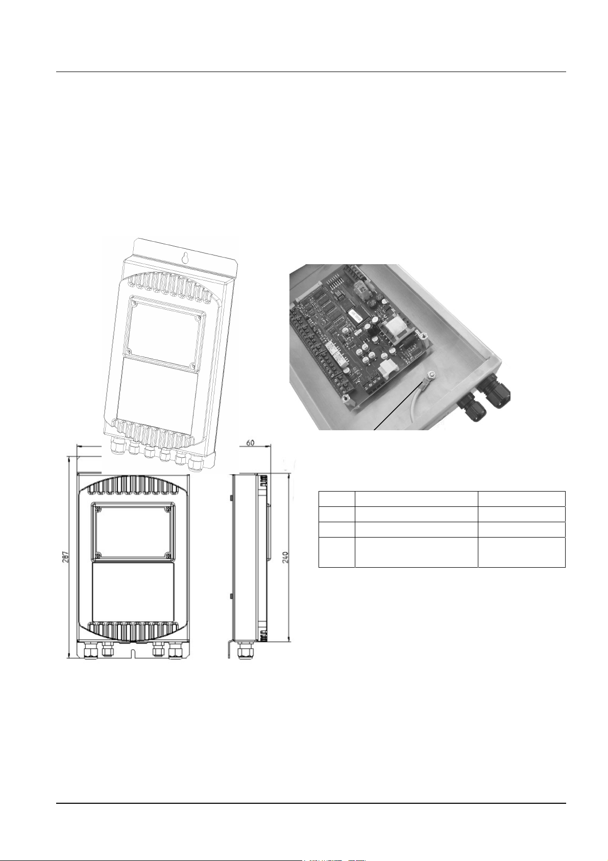
3.1 Wall mounting unit
3.1.1 Layout and Ground connection
The back cover can be opened by removing the 4 screws on the back side of the HydrovarSmart. For the arrangement of the control terminals, please refer to chapter 4.
The grounding has to be done according to the following pictures.
Ground connection
pcs. Cable gland type Max.Cable Ø
2 M16x1,5 10mm
2 M12x1,5 7,5mm
2 Rubber plug for
7,5mm
M12
All dimensions in mm
9
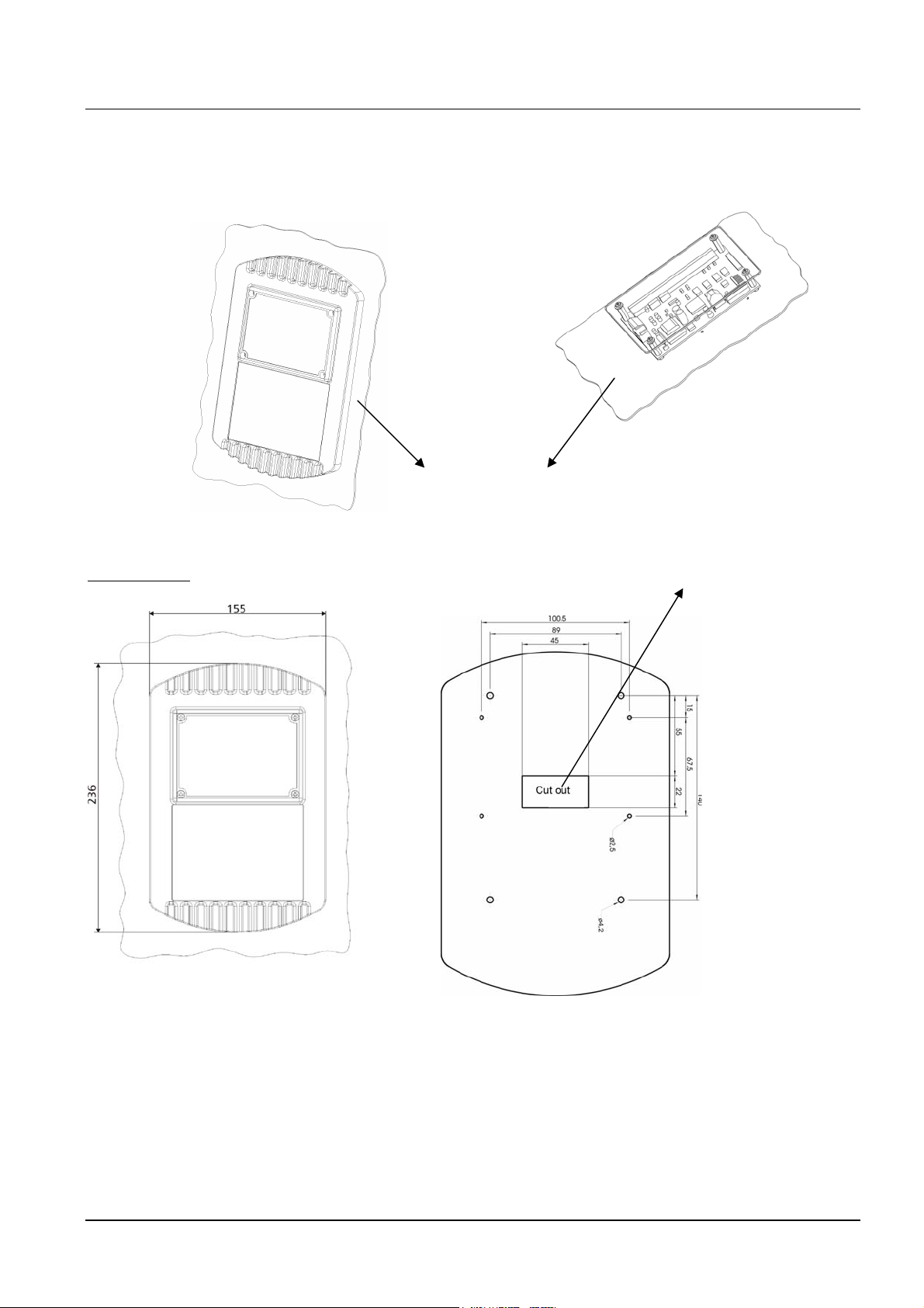
3.2 Panel mounting unit
3.2.1 Layout and Ground connection
Panel door
The proper ground connection has to be realised over the panel door. No additional
grounding required!
Dimensions:
Cutting or punching
All dimensions in mm
You can find the drilling plan in
the real dimensions 1:1 on an
enclosed sheet.
10
3.2.2 Included Component
Æ 1 x HYDROVAR-Smart print
Æ 1 x Display unit
Æ 1 x Display-sealing
Æ 1 x Front cover
Æ 1 x Protection cover
Æ 1 x Label (SCH 60.25)
Æ 1 x Label (SCH 60.35)
Æ 4 x Distance bolt M4xM4x22 I/I
Æ 4 x Distance bolt M4xM4x8 A/I
Æ 4 x Screw M3x10
Æ 4 x Screw M4x10
Æ 4 x Screw M4x6
Æ 8 x Washer M4
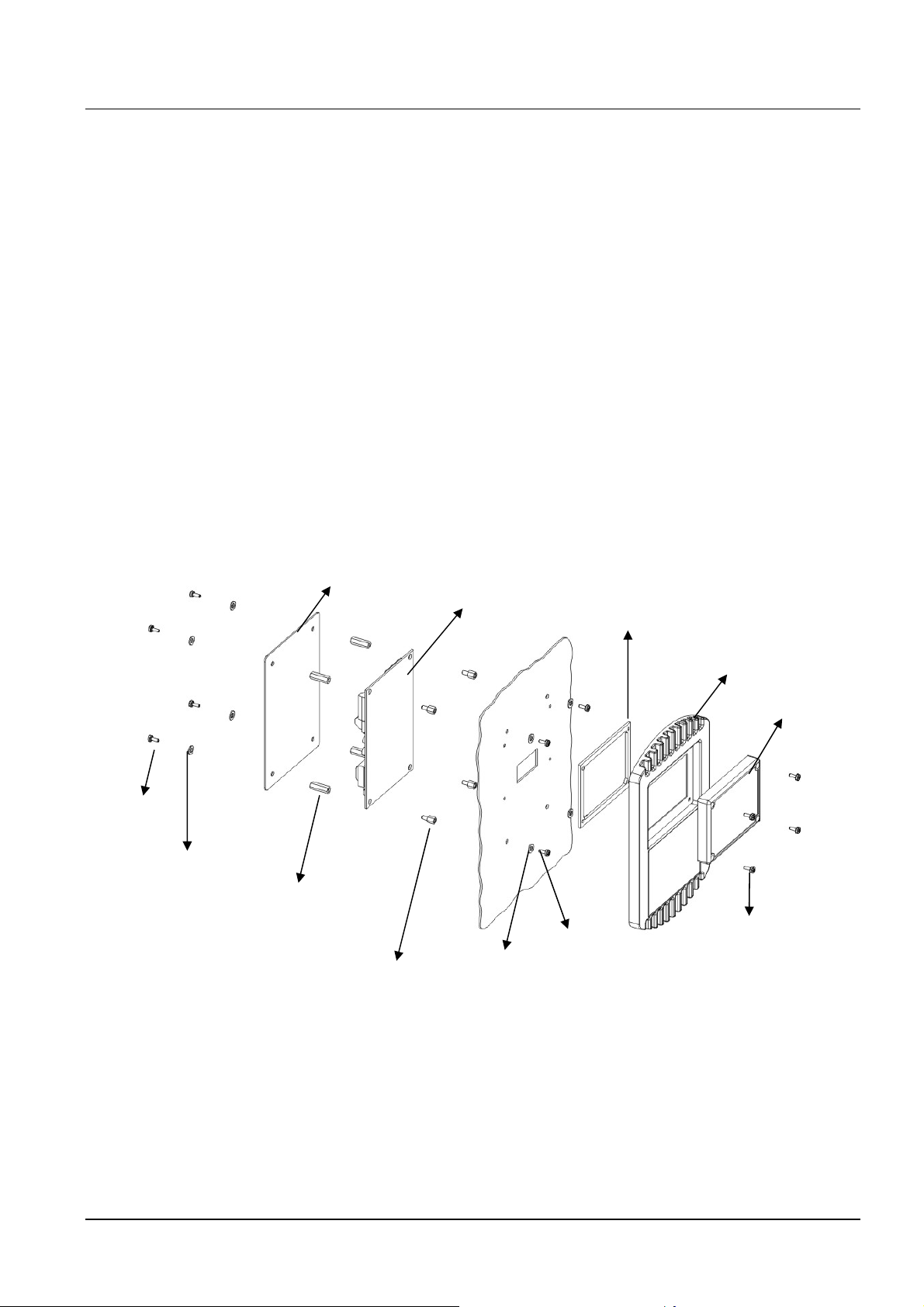
3.3 Explosion drawing
Protection cover
HYDROVARSmart print
Display-sealing
Front cover
Display unit
M4x10
Washer M4
Distance boltM4xM4x22 I/I
Distance bolt M4xM4x8 A/I
Washer M4
M4x6
M3x10
The self-adhesive label SCH 60.25 (with the cut-out for the display) has to be fixed in this
way, that the yellow areas are placed on top of the push buttons.
The self-adhesive label SCH 60.35 has to be fixed below the display unit.
A photo of the right place for these labels is shown on the first page of this instruction
manual!
11
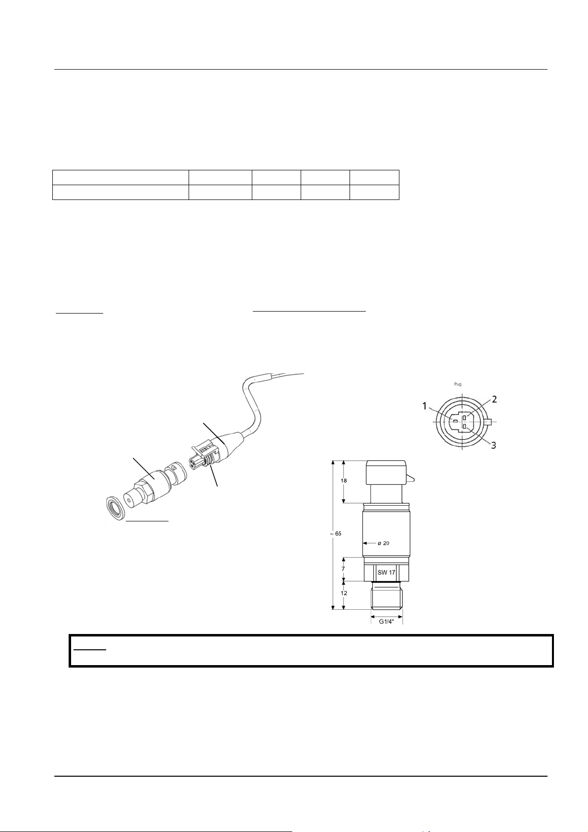
3.4 Pressure transducer PA-22S (4-20mA)
The sensor of this transmitter is a piezoresistive silicon pressure sensor, mounted on a tape
(TAP) freely floating in an oil chamber. The pressure is transferred to the sensor by a
separate steel diaphragm in the oil chamber.
Specification
Range (FS): 10 bar 16 bar 25 bar 40 bar
Max. pressure – P
: 20 bar 30 bar 50 bar 80 bar
max
Class of protection IP 67
Output signal: 4...20 mA; 2-wire
Supply: 8 – 28 VDC
Operating temperature: -10...80°C compensated (max. –40...135 °C)
Storage temperature: -40...135°C
Cable length: 2 m (screen)
Material:
Body: 1.4435
Diaphragm: 1.4435
Thread: G ¼“
Electrical connection:
White = Analogue output signal (+ Out) (1)
(2) not used
Brown = Supply voltage (+ VCC) (3)
Plug / cable
Pressure transmitter
Gasket
Gasket Viton®
Measures in mm
Note: To guarantee the protection class IP67, the rubber gasket has to be
mounted between the pressure transducer and the plug!
4 Control Terminals and Display unit
All externally used cables must to be shielded. Do not connect the ground of the electronic
components to other potentials (all electronic ground and GND of the RS 485-interface are
connected together internally).
12

For external on/off switches, (terminals X1/4 – X1/5) contacts, which are suitable for
switching low voltages <10 VDC, are necessary.
If unshielded control cables are used, signal interference may occur and interfere
with the function of the controller.
Terminals:
X1/ 1 GND
2 Actual value input 4...20mA, 50 Ohm internal load resistance
3 Power supply for external transducer; 15VDC, max. 100mA
4 GND
5 5 VDC for external on/off (release); Ri=10kOhm,
(gold plated contact necessary!)
6 GND
7 5 VDC for external low water protection; Ri=10kOhm,
(e.g. incoming pressure switch or water level switch)
8 Thermal switch or PTC (in motor terminal box)
9 Thermal switch or PTC
10 GND
11 Analogue output 2; 0...10 VDC (see chapter 7.25)
12 Current signal input 4...20mA
13 Voltage signal input 0...10V or 2...10V
14 Digital input for activating of 2nd required value
Terminal:
X2/ 1 Fault signal relay NC max. 250VAC 1A free of inductivity
(for dry 2 Fault signal relay CC max. 250VAC 1A free of inductivity
Contacts) 3 Fault signal relay NO max. 250VAC 1A free of inductivity
4 Pump operation
NC max. 250VAC 1A free of inductivity
signal relay
5 Pump operation
CC max. 250VAC 1A free of inductivity
signal relay
6 Pump operation
NO max. 250VAC 1A
free of inductivity
signal relay
!! Fault relay (X2/2 - X2/3) is closed, when there is no error!!
Terminal:
Terminal:
2
3
4
X3 Display
X5-6/ 1 RS 485 SIO - LOW
RS 485 SIO + HIGH
RS 485 GND
RS 485 + 5 VDC
max. 20mA out
For supply of external interface converter
Terminal:
X8 RS 485
Terminal: X9/ 1 24 VAC or DC Supply Voltage
2 24 VAC or GND Supply Voltage
3 Error relay of the connected VFD
4 Error relay of the connected VFD
5 Analogue output for the speed signal of the VFD (0-10V DC)
6 GND
13
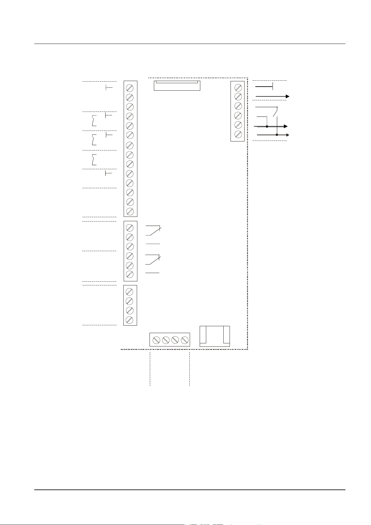
4.1 Terminals of the HYDROVAR-Smart
f
N
t
NC N
N
N
Screen
Actual value signal input 4-20mA
+15 VDC max. 100mA
External on/of
External low Water
Display
X
1
2
3
4
5
6
7
X 1
X3
9
6
5
4
3
2
1
Error Relay of the VFD
GND
Analogue output 1 (0-10V)
to the VFD
GND
DC +supply
Supply Voltage
Motor thermal switch or PTC
Ground
Analogue output 2; 0-10V
Current signal input 4..20mA
Voltage signal input 0..10V or 2..10V
Digital inpu
Fault signal
Pump running signal
RS 485
CC
CC
SIO -
SIO +
GND
+ 5V
C
O
O
12
14
8
9
10
11
13
1
2
3
4
5
6
1
2
3
4
X2
HV – Smart Controlcard HV – Smart Controlcard
X
5
X
8
X
6
1
3
4
2
+
O
I
S
RS 485
V
D
5
O
+
G
I
S
RS 485
When connecting more variable speed drives (max. 4 pumps) via the interface RS 485, the
terminals X5/1/2/3 or X6/1/2/3 of each Hydrovar-Smart have to be connected together by
using a shielded cable and have to be programmed accordingly.
14

4.2 Display unit
ON
OFF
Select
Power supply OK
Run indication
Fault indication
5 Language Selection
The information on the display can be called up in German, English, Italian, French,
Spanish, Portuguese or Dutch.
To select the required language proceed as follows:
Briefly press ¾ and Ï simultaneously (in 1st display);
⇒ the actual language will now appear in the second line and the desired language can be
selected with the buttons Ï or Ð. After the language has been selected, press ¾ briefly
and the 1
If only the language is changed it is not necessary to SAVE.
st
display of the main menu will appear again.
15
6 Parameters of the main menu
After connection of the Hydrovar-Smart unit to the power supply the following displays
become visible.
SW-Ver: HV00-001
Date: xxxx
The following two displays are depending on the selected mode:
a) Active MODE = Controller:
1.
XYLEM
XX.X BAR
Continue by pressing the ¾-button
2.
REQUIRED VALUE 1
X.XX BAR
If several pumps are connected via the RS-485 interface, one pump must be ready for
operation when the set pressure is changed, otherwise the set value will not be accepted
by the follow-up pumps. Afterwards the new required pressure has to be saved in all
pumps.
If you want to change to Required Value 2 you have to close the external contact,
connected to X1/10-X1/14.
After closing this contact, the display changes from Required value 1 to
2.1 REQUIRED VALUE 2
ADC-X XX.X BAR
ADC-X: This parameter shows the source of the external or internal value.
XX.X Bar: shows the actual value of the Required Value 2.
Continue by pressing the ¾-button (to point 3)
The current software version with the date of
programming is displayed for about 3s.
This window is mentioned several times in the
Operating Instructions as 1st display at Mode Controller
Set the desired set pressure with either Ï or Ð and
then briefly press the ¾-button.
In this window, there is shown the condition of
the second Required value.
16
b) Active MODE = Actuator:
1.
XYLEM
Frequency XX.X Hz
This window is mentioned several times in the
Operating Instructions as 1st display at the Mode
Actuator.
Continue by pressing the ¾-button
2.
REQUIRED VALUE 1
X.XX BAR
Not active in the actuator mode, because the
internal controller is not active.
Continue by pressing the ¾-button (to point 3)
c) Active MODE = Synch. Controller or Multicontroller:
1.
ADR (X) P X
XX.X Bar
This window is mentioned several times in the
Operating Instructions as 1st display in the
Synch. Controller or Multicontroller mode.
Continue by pressing the ¾-button
2.
REQUIRED VALUE 1
X.XX BAR
Set the desired set pressure with either Ï or Ð and
then briefly press the ¾-button.
If several pumps are connected via the RS-485 interface, one pump must be ready for
operation when the set pressure is changed, otherwise the set value will not be accepted
by the follow-up pumps. Afterwards the new required pressure has to be saved in all
pumps.
If you want to change to Required Value 2 you have to close the external contact,
connected to X1/10-X1/14.
After closing this contact, the display changes from Required value 1 to
2.1
REQUIRED VALUE 2
ADC-X XX.X BAR
In this window, there is shown the condition of
the second Required value.
ADC-X: This parameter shows the source of the external or internal value.
XX.X Bar: shows the actual value of the Required Value 2.
Continue by pressing the ¾-button (to point 3)
d) Active MODE = Manual control:
1.
XYLEM
Frequency XX.X Hz
This window is mentioned several times in the
Operating Instructions as 1st display at the Mode
Manual control.
Continue by pressing the ¾-button
17
2.
MANUAL LOCAL
X.X Hz X.XX BAR
Set the desired output frequency with either Ï or Ð
and then briefly press the ¾-button.
If several pumps are connected via the RS-485 interface, you have to set this
parameter on each pump!
Press the ¾ button on the Hydrovar-Smart to change to
!! The following displays of the main menu are valid for all selected Modes !!
3.
AUTO - START
Select (ON) with the Ï button or (OFF) with Ð .
ON
AUTO-START ON starts the pump automatically after a failure of the power supply.
If AUTO-START is OFF, the Hydrovar-Smart has to be restarted by pressing the buttons Ð
(OFF) and then Ï (ON) after a power supply failure.
If the AUTO-START is OFF, the unit will not start again in cases of a power supply failure or
disconnection. After restarting the following message is shown:
3.1
NO AUTOSTART
disable inverter
To restart the unit, press at first the Ð and then the Ï button for the start.
Press ¾ and the display changes to
Note:
4. E R R O R 1
All errors are only readable in English language
Here, there is shown the last error
.........................
Press the ¾ button to change to
5. E R R O R 2
Shows the error before the last error
.........................
Press the ¾ button to change to
6. E R R O R 3
Shows the error before error 2
.........................
Press the ¾ button to change to
7. E R R O R 4
Shows the error before error 3
.........................
Press the ¾ button to change to
8. E R R O R 5
Shows the error before error 4
.........................
Press the ¾ button to change to
18
9. TOTAL RUN TIME
0000:00
Runtime of the motor.
This time can be reset together with the
Operating hours.
Press the ¾ button to change to
Note: All changes have to be saved, that they will not be lost in case of shut off
of the power supply !!
10.
SAVE ???
Simultaneously press buttons Ï and Ð until...:
Ï + Ð
11.
SAVE ???
SAVED
appears on the display. After five seconds the
display jumps back to the 1st display.
These parameters can also be set during operation; To do so, briefly press the button ¾
and repeat steps 1 – 10.
Note: Often shown displays:
12.
INVERTER LOCKED
enable inverter
This message appears when the connection of
terminal X1/4-X1/5 is open (external release contact).
To start the Hydrovar-Smart, connect these terminals by closing the external release contact
or by using a short-circuit connection!
19
7 Settings in the Secondary Menu
Important! Before entering the secondary menu, these instructions
have to be read carefully to prevent incorrect settings which could cause
malfunction.
Secondary Menu:
In the following paragraphs all possible settings are listed (in the display, there
is shown the European default setting).
INVERTER STOP
ON -> START
PASSWORD
0000
PASSWORD
0066
Stop motor by pressing Ð (OFF)
Press ¾ for 3 seconds to change to
Set ‘Password 0066’ by pressing Ï
Note: The password must be entered at each entry!
J O G – MODE
0.0Hz X.XX Bar
Confirm by pressing ¾ and the first window of the sub
menu is shown
7.1 JOG-MODE
Display and Manual Operation Mode
J O G – MODE
0.0Hz X.XX Bar
Actual outgoing frequency and actual analogue input
are shown. By pressing Ï or Ð in this menu, the
internal controller of the Hydrovar-Smart will be shut off and the inverter changes to
manual mode. With the buttons Ï and Ð you can set any constant speed.
Setting of 0,0 Hz stops the inverter. If the JOG-MODE is left at a frequency higher than 0,0
Hz the inverter will continue its normal automatic operation.
Press ¾ on the Hydrovar-Smart to change to
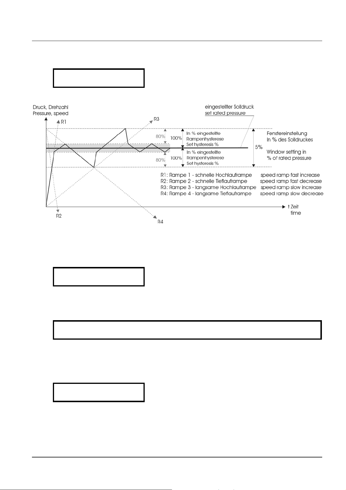
7.2 Window - %
WINDOW
5%
This value indicates the max. variation of the outgoing
pressure.
Possible setting: between 0% - 100% of required value.
Press ¾ on the Hydrovar-Smart to change to
20

7.3 Ramp Hysteresis
RAMP HYSTERESIS
80%
Level, where the fast ramps are changing to the slow
ramps
Possible setting: between 0%..100% of the window
Press ¾ on the Hydrovar-Smart to change to
7.4 Ramp 1: Fast running up time:
Time setting at Ramp 1, 2, 3, or 4 will influence the control of the pump and
MUST NOT BE CHANGED at normal operation. Possible setting of each ramp
0,05 - 1000 sec.
Please take care, that the ramp times of the connected VFD are every time faster than the
settings of the ramps 1-4 of the HYDROVAR-Smart!
The fast ramp times 1 and 2 are determined by the power of the connected drive.
(Standard settings = 4-15s, depending on the power)
RAMP 1
4.0 Sec
Excessively fast running up time may overload the
inverter in the starting moment.
Excessively slow running up time may cause a break
down of the outgoing pressure during operation.
Press ¾ on the Hydrovar-Smart to change to
7.5 Ramp 2: Fast running down time:
RAMP 2
4.0 Sec
Excessively fast running down time tends to cause
oscillation or hunting or can cause an error
(OVERVOLTAGE) during ramp down of the pump.
Excessively slow running down time tends to generate over pressure.
Press ¾ on the Hydrovar-Smart to change to
7.6 Ramp 3: Slow running up time:
The following ramps 3 and 4 determine the speed of the internal Hydrovar-Smart controller
and depend on the system, which should be controlled.
RAMP 3
70 Sec
A too slow running up time can cause a break of the
outgoing pressure during variation of the demand.
A too fast running up time may lead to oscillation
and/or overload of the inverter.
Press ¾ on the Hydrovar-Smart to change to
21
7.7 Ramp 4: Slow running down time:
RAMP 4
70 Sec
Diagram: Ramp – Window
A too fast setting leads to oscillation
A too slow setting delays the switching off too much
Press ¾ on the Hydrovar-Smart to change to
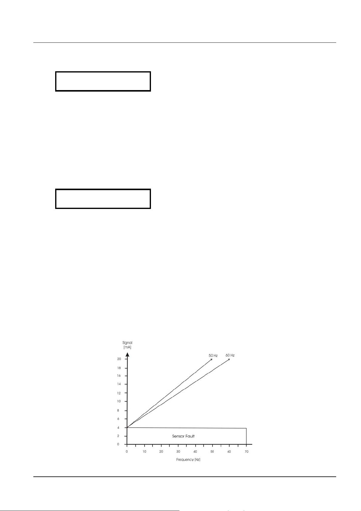
7.8 Maximum Frequency
MAX. FREQUENCY
50.0 Hz
Possible setting between 40 and 70 Hz.
The Hydrovar-Smart gives an analogue output signal of 0-10VDC as a speed signal, which is
connected to the frequency drive, where 0V corresponds to 0Hz and 10VDC corresponds to
the maximum frequency.
It is important that this values correspond with the values of the inverter.
Note: The setting of the Maximum frequency in the HYDROVAR-Smart has to
be the same than in the connected VFD!
Press ¾ on the Hydrovar-Smart to change to
7.9 Minimum Frequency
MIN. FREQUENCY
0.0 Hz
Here you can set the minimum frequency between 0,0
and the Maximum frequency.
Attention!: If there is set f>fmin in the parameter CONFIG. FMIN the pump will not stop in
the normal mode. It will keep running with the set minimum frequency.
!! Possibility of overheating of the pump !!
Press ¾ on the Hydrovar-Smart to change to
22
7.10 Operation at the minimum frequency
CONFIG FMIN
f => fmin
If you have selected „f->0“ the frequency will go
down to the selected minimum frequency.
Then the inverter will keep running for the selected stop-delay time and after this time the
Hydrovar-Smart will stop automatically.
If the selection is „f->f
“ you can not run the pump below the set minimum frequency. In
min
the controller, actuator and multi controller mode the pump will never run below the set
minimum frequency (the pump will only stop with an external on/off-(terminals X1/4 and
X1/5) or in case of a failure.
Press ¾ on the Hydrovar-Smart to change to
7.11 Delay time for shut off at minimum frequency
STOP-DELAY FMIN
5 s
After running the pump for this selected time at
minimum frequency, the pump will stop, if parameter
CONFIG. FMIN is set to f ⇒ 0
Adjustable between 0 and 100s.
NOTICE!
Problems with shut off of the pump at 0 demand (too small or no pressure tank) can be
solved by using these settings!
Additional function: selectable delay time to start a full speed pump in case of “Simple
Multicontroller” mode.
Press ¾ on the Hydrovar-Smart to change to
7.12 Sensor – Adjust
SENSOR_ADJUST?
Out of range
Zero point adjustment of the transmitter
Depressurise the system and press buttons Ï + Ð
simultaneously. After a successive adjustment, "adjusted" appears on the display.
If “out of range” is shown on the display, no adjustment is possible
Press ¾ on the Hydrovar-Smart to change to
7.13 Sensor - Curve
SENSOR-CURVE
Linear
Function of the input signal (4...20mA) of the
Hydrovar to the actual measured value.
Application:
linear: Pressure control, differential pressure control, level, temperature and flow control
(inductive or mechanical).
quadratic: Flow control by using an orifice plate together with a differential pressure
transmitter.
Press ¾ on the Hydrovar-Smart to change to
23
7.14 Setting of the sensor range
SENSOR RANGE
20mA = 10.0Bar
Setting of the maximum value of the measuring
transmitter, which corresponds to
20mAe.g. 10.0 bar = 20mA of the pressure transmitter
Adjustable ranges: Bar: 0.2...100 bar; psi 2.9...1450psi;
m3/h: 4...2400m3/h; g/min: 9...10560g/min
mH2O: max 1019,5mH2O; ft: max 3345ft
0...100 %; or without unit: max 1000;
Press ¾ on the Hydrovar-Smart to change to
7.15 Operation Mode
MODE:
Controller
Select your required Mode by using the Ï and Ð
buttons
If only one HYDROVAR-Smart pump is in operation set the Controller. If more than one
pump work together via the RS485 interface (follow-up pump control), the Multicontroller
must be set with the buttons Ï or Ð.
Synch. Controller:
The Synchronous Controller mode is working in the same way like the Multicontroller. The
only difference is, that all pumps in a multipump system are running at the same
frequency.
Actuator:
The Actuator application is only used if you have another external controller. Then the
internal controller is shut off, and the output frequency is proportional to the input signal
(X1/2) ⇒ 4-20 mA = 0 - f
. The outgoing signal changes with the programmed ramps 1
max
and 2. The functions of low water, thermal protection and external ON/OFF are still
working.
24
If MANUAL CONTROL is selected, the parameter REQUIRED VALUE will change to MANUAL
CONTROL in the main menu, where the actual frequency and the actual value is displayed
(according to the JOG-MODE in the submenu).
Now the frequency can be changed with the Ï and Ð buttons, and the speed of the pump
will change with the fasten ramps. After selecting the right frequency, it can be saved with
the standard SAVE.
After a supply failure, the pump will then run with this selected frequency (depending on
the parameter AUTO-START).
The frequency can be changed between the set minimum and maximum frequency.
In the 1st display, there is shown the actual frequency.
NOTE:
CONFIG. FMIN will not work in this mode.
Attention
Driving the pump in a not allowed speed range can damage the motor or the
inverter!
Press ¾ on the Hydrovar-Smart to change to
7.16 Control Response
REGULATION MODE
Normal
Normal: Speed is increased with falling actual value
signals. (e.g.: Control at constant output pressure).
Inverse: Speed is reduced with falling actual value
signal, (e.g.: Control at constant suction pressure or at
constant level).
Press ¾ on the Hydrovar-Smart to change to
7.17 Start Value
START VALUE
disabled
This parameter gives you the start value after pump
stop in percentage of the required value (adjustable
between disabled and sensor range).
Example:
required value: 5,0 bar
start value: 2,5 bar
If the pump system have reached the required pressure from 5.0 Bar and there is no more
consumption, the Hydrovar-Smart shuts off the pump. When the consumption increases
and the pressure goes down the pump will normally start. If you have selected the START
VALUE at 2,5 bar the pump will start again at this selected pressure.
Press ¾ on the Hydrovar-Smart to change to
25

7.18 2
nd
Required Value
CONFIG. REQ. VAL.2
OFF
With this parameter CONFIG. REQ. VAL.2 you can
select a independent 2nd required value.
The change between 1st and the 2nd required value can be done over the digital
input, terminal X1/14 on the control card. If this input is connected to Ground,
2nd required value active.
Possible settings:
OFF: actual value 2 is not active (no change after closing the input X1/14)
INT: internal required value 2, function and setting according to existing required
value.
EXT ADC-I: the required value 2 is made from the value of the current signal (4-
20mA) at the terminals X1/12, X1/10. 20mA is equal to the programmed
SENSOR RANGE. If the incoming current signal is below 4mA, there will be
shown an error message on the display, but no failure is indicated (failure relay
is not closed). In this case the required value 2 will be 0.
EXT ADC-U 0-10V: the required value 2 is made from the value of the voltage signal
of 0-10VDC at the terminals X1/13, X1/10 (Ground)
EXT ADC-U 2-10V: the required value 2 is made from the value of the voltage signal
of 2-10VDC at the terminals X1/13, X1/10 (Ground)
Example for connection of an external 4-20mA signal for the 2nd required value:
Setting the required value2:
The active required value is shown in the actual display of the parameter required value.
When the 2nd required value is active (digital input, terminal X1/14, closed), in the first line,
nd
there is shown Required value 2. The second line will show the source of the 2
value,
which is selected in the parameter CONFIG. REQ VAL:2 (INT, EXT-ADC-I or EXT-ADC-U) and
also the actual value of this input.
INT: you can select your value with the Ï and Ð buttons
EXT: only display of the value of the 2
nd
analogue input signal.
In case of saving, every time both required values are saved.
Press ¾ on the Hydrovar-Smart to change to
26
7.19 Configuration of 1
RELAY CONFIG.
Simple Multicontr.
st
relay
Selection possible with buttons Ï and Ð.
Run Motor ⇒ motor run indication (over the relay)
Simple Multicontr. ⇒ allows to start/stop a constant speed pump
Enable Seq.Ctl. – this will be the start frequency of the slave pump
Synchron. Limit – this will be the stop value of the slave pump
Stop Delay fmin. – this will be the delay time before starting the slave pump.
e.g. if the speed controlled pump reaches the start level, the relay will be switched on,
and will be switched off, when the output frequency falls below the stop level.
Press ¾ on the Hydrovar-Smart to change to
7.20 Submenu Offset
S U B M E N U
Offset
Press ¾ for about 3 seconds to enter the submenu
and the display changes to
7.20.1 Source of the Offset input
OFFSET INPUT
Off
The second additional input can be used as required
value 2 and also for an Offset of
the 1st required value.
(Example:)
OFF : Offset deactivated
EXT ADC-I : Offset will be calculated according to the current input (4-20mA) at
the
terminals X1/12 (X1/10=Ground).
Note:
If the incoming current signal is below 4mA, there will be an error message on
the display, but no failure is shown (failure relay is not closed). In this case the
OFFSET INPUT works like external signal=0.
EXT ADC-U 0-10V: Offset will be calculated according to the voltage input of 0-
10VDC
at terminals X1/13 (X1/10=Ground)
EXT ADC-U 2-10V: Offset will be calculated according to the voltage input of 2-
10VDC
at terminals X1/13 (X1/10=Ground)
Press ¾ on the Hydrovar-Smart to change to
27

7.20.2 1
st
Offset level
LEVEL 1
XX.X %
analogue input).
The level 1 is the start level of the 1st Offset.
(adjustable between 0 and 100% of the additional
Press ¾ on the Hydrovar-Smart to change to
7.20.3 2
nd
Offset level
LEVEL 2
XX.X %
analogue input).
The level 2 is the start level of the 2nd Offset.
(adjustable between 0 and 100% of the additional
Press ¾ on the Hydrovar-Smart to change to
7.20.4 INTENSITY 1
INTENSITY 1
+XX.X %
Settings: -200% up to +200% of the sensor range.
This is the intensity of the 1st Offset of the required
value at the zero point of the second analogue input
Press ¾ on the Hydrovar-Smart to change to
7.20.5 INTENSITY 2
INTENSITY 2
+XX.X %
This is the intensity of the 2
value at the maximum point of the second analogue
nd
Offset of the required
input.
Settings: -200% up to +200% of the sensor range.
To leave the submenu press the ¾ longer than 3 sec. to change to
S U B M E N U
Offset
28
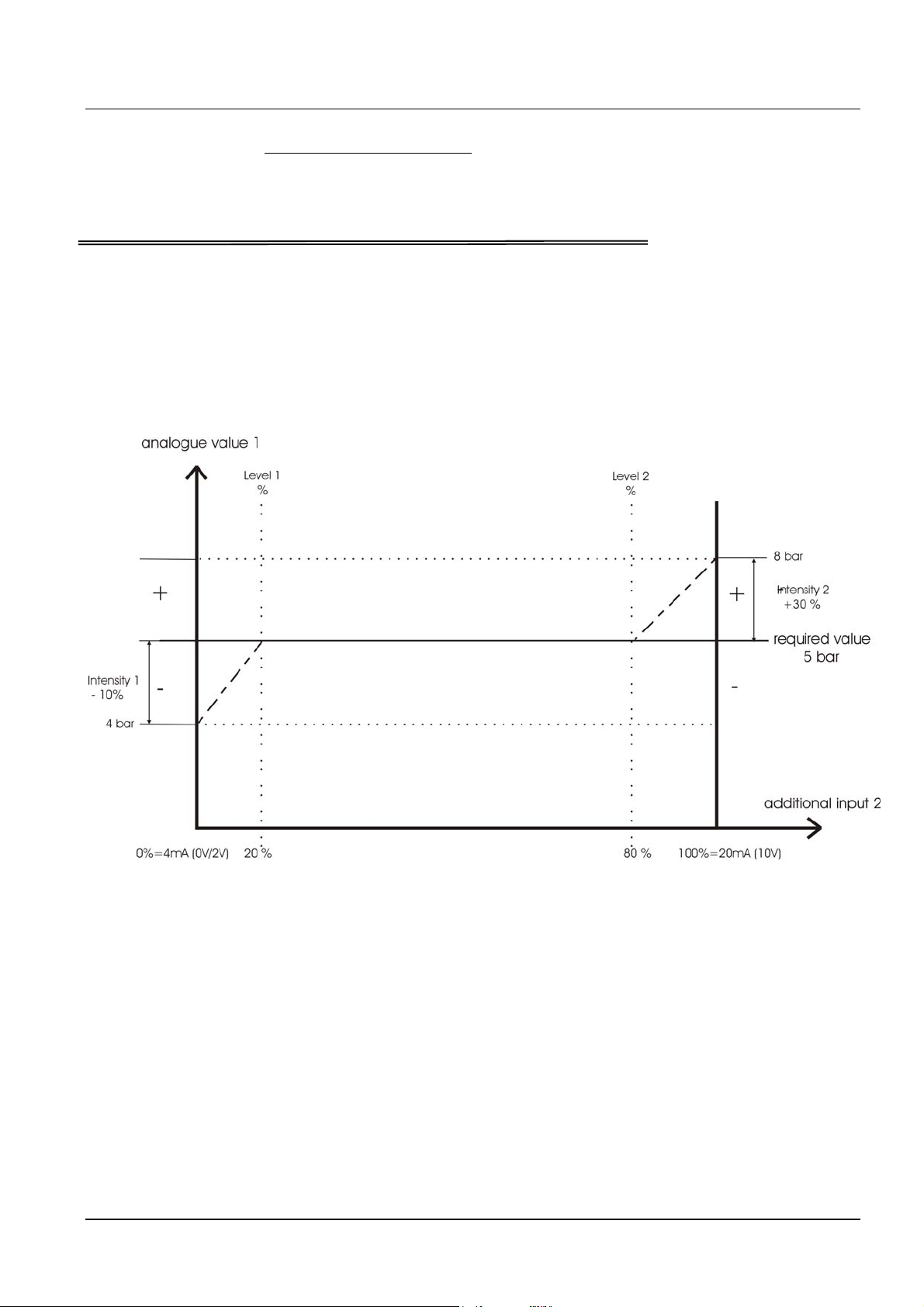
7.20.6 Example for the Offset:
Sensor range: 20mA ≙ 10 bar
Required value: 5 bar
Level 1: 20% of the 2nd additional input
Level 2: 80% of the 2nd additional input
Intensity 1: -10% ≙ -1 bar (refer to the required value)
Intensity 2: +30% ≙ +3 bar (refer to the required value)
The Level 1 have to be entered on the axis of the “additional input” in percent of this
Second Additional input (=20%). Also proceed with the second level (80%).
Intensity 1 and 2 are depending on the Sensor range of the actual value signal.
The offset of Intensity 1 is valid till Level 1. After reaching Level 1 the Required Value has
no offset. Therefore you have to enter the Intensity 1 at the 0%-axis to fine the right offset
value.
The Required Value is valid till you reach the Level 2. After reaching Level 2, the new value,
is influenced by the offset of Intensity 2. To get the right offset after Level 2, you have to
enter the Intensity 2 at the 100%-axis of the additional input.
Press ¾ on the Hydrovar-Smart to change to
29

7.21 Submenu Sequence control
S U B M E N U
Seq. Control
Programming of the Multipump Operation:
Up to four pumps can be connected using the integrated RS-485 interface, by connecting
the terminals /1, /2 and /3 of the terminal blocks X5 or X6 of each pump together).
However, the following additional programming must be carried out in the submenu:
Press ¾ for about 3 seconds to enter the submenu and the display changes to
7.21.1 Lift Value
ACTU. VALUE INC.
0.35 Bar
Adjustable between 0.0 to the pre-selected
Sensor range
Operation of the start of the slave pump:
1) Pump 1 reaches ENABLE SEQ. CONTROL (maximum speed)
2) Pressure falls and reaches the start-value of the 2
nd
pump
(= REQUIRED VALUE – ACTU. VALUE DEC.)
3) Pump 2 is switched on automatically
4) The required value is calculated new, after the start of the 2
nd
pump in the
following way!
New required value = REQUIRED VALUE – ACTU. VALUE DEC. + ACU. VALUE INC.
Generally:
k ... Number of active pumps (k >1)
p = p
• Lift value = Fall value ⇒ Pressure constant when pumps switch on
• Lift value > Fall value ⇒ Pressure rises when lag-pump switches on
• Lift value < Fall value ⇒ Pressure falls when lag-pump switches on
+ (k-1)*[lift value – fall value]
set
30

Press ¾ on the Hydrovar-Smart to change to
7.21.2 Fall Value
For calculation of the set pressure after start of pumps 2 to 4
ACTU. VALUE DEC.
0.15 BAR
Adjustable from 0,0 to pre-selected Sensor range
determines the start-value of the 2nd pump and the
other following pumps.
(Start-Value = REQUIRED VALUE –ACT. VALUE DEC.)
Press ¾ on the Hydrovar-Smart to change to
7.21.3 Release frequency of the following controller
ENABLE SEQ. CTL.
48.0 Hz
Release of the follow-up pump only when the startvalue is reached and
the lead
Pump has reached the programmed frequency (Adjustable from 0.0 Hz to 70 Hz)
If you do not want to start a following pump this value has to be set higher than the
maximum frequency.
This parameter is also used to start a constant speed pump (when Simple Multicontr. is
set). When this frequency level is reached, the potential free contact of the relay X2/5 –
X2/6 will be closed.
Press ¾ on the Hydrovar-Smart to change to
31

7.21.4 Switch Interval
SWITCH INTERVAL
12 hours
For changing the master pump and follow-up pump in
order to achieve even operating hours of the pumps
Adjustable between 1 hour and 100 hours. If it is set higher than 100 hours, the
automatic changeover is deactivated).
Manual change of master pump in the 1st display with the Ï-button.
Press ¾ on the Hydrovar-Smart to change to
7.21.5 Source of required value
SOURCE REQ. VALUE
OFF
for selecting the pump address of the source of the
required value.
Five settings are possible:
OFF, ADR1,ADR2, ADR3 and ADR4. If an additional input (INT or EXT-ADC-I or EXT-ADCU) is active, you must select the address where this input is connected.
When Multicontroller or Synch. Controller is active, the actual active value is shown in
brackets in the middle of the display. If the sign “#” is shown in the second line of the
display, the pump will work with a required value from another pump in the multipump
system. On the pump, which is the source of the required value, there is no “#” shown.
Press ¾ on the Hydrovar-Smart to change to
7.21.6 Synchronous Control
If the synchronous control is active the activated pumps try to control the set pressure
together (all pumps run at the same frequency). The 2nd pump starts, when the 1st pump
reaches the release frequency (ENABLE SEQ. CONTR.) The pumps will now maintain
constant pressure by running synchronously. The follow-up pump will stop, when both
pumps together run below the set SYNCHRON. LIMIT. This creates the hysteresis effect.
S U B M E N U
Synch. Control
Press ¾ for about 3 seconds to enter the
submenu and the display changes to
7.21.6.1 Synchronous Limit
SYNCHRON. LIMIT
0,0 Hz
Frequency threshold adjustable between 0,0 Hz and
the set maximum frequency.
Switch off threshold of the first follow-up pump. The switch off thresholds of the other
pumps are each higher by the SYNCHRON-WINDOW.
This parameter is also used for the stop value for the external constant speed pump at
activated Simple Multicontroller in the parameter configuration relay.
Press ¾ on the Hydrovar-Smart to change to
32

7.21.6.2 Synchronous Window
SYNCHRON-WINDOW
2.0 Hz
Frequency offset
Adjustable between 0...10 Hz
Threshold lift for switching off the 3rd and 4th follow-up pump.
Setting the Synchronous Limit:
1. Set the desired set value and close the outgoing valves for no flow.
2. Start the first pump in JOG Mode (1st Window in the submenu), increase the frequency,
till you reach the required value. Read the frequency ( = f0 )
3. Set the synchronous threshold (f
+ 2-3 Hz)
0
4. Set the synchronous offset to 1-2 Hz
(depending on the pump curve and operating point).
To leave the submenu press the ¾ longer than 3 sec. to change to
S U B M E N U
Synch. Control
Press ¾ on the Hydrovar-Smart to change to
7.21.7 Pump status indication
PUMP – SEQUENCY
Adr1 disabled
Shows the status of the individual drives
- for follow-up pump switching
- settings from address 1 to 4, (address 5 is reserved for external control
devices)
- Information concerning the actual sequential status of each pump.
The following diagnosis parameters can be also be read in this display window:
hold Px Pump is stopped (control released)
run Px Pump is running (control released)
stop Px Pump is stopped, because f< start frequency of the previous
pump
Disabled Hydrovar-Smart not ready to start (no release)
Error Hydrovar-Smart error
Fault Polling failure (RS-485)
(interface connection wrong or not connected)
Detected Polling successful (RS-485)
AdrX * “*” -> Address of the pump that is being read
Press ¾ on the Hydrovar-Smart to change to
33

7.21.8 Error Signals for Data Bus Interruptions
BUSARBIT-DIAG.
0
Counts the number of fault synchronising attempts
over the RS-485 interface.
Is there an indication >100, the RS485 interface connection has to be checked!
To leave the submenu press the ¾ longer than 3 sec. to change to
S U B M E N U
Seq. Control
Press ¾ on the Hydrovar-Smart to change to
7.22 Submenu - RS 485 Interface
S U B M E N U
RS 485-Interface
Press ¾ for about 3 seconds to enter the submenu
and the display changes to
7.22.1 Pump Address
PUMP-ADDRESS
OFF
If only one pump is used, the setting remains OFF. If
several pumps are connected via the RS-485
interface (max. 4) each pump must be allocated its own address number.
Each address may only be used once!
Press ¾ on the Hydrovar-Smart to change to
7.22.2 ADC Reference
ADC REFERENCE
Local
Reference for the local ADC (Analogue/DigitalConverter) or SIO (RS485 interface).
LOCAL: Actual value from transmitter (Terminal X1/ 1-2)
REMOTE: Actual value via RS-485 (Terminal X5 or X6 / 1-2-3)
To leave the submenu press the ¾ longer than 3 sec. to change to
S U B M E N U
RS 485-Interface
Press ¾ on the Hydrovar-Smart to change to
34

7.23 Compensation Frequency
Control according to a system curve (increase of the set pressure, depending upon the
flow rate or speed).
FREQU. – LIFTING
30.0 Hz
Adjustable between 6 Hz and the set MAXIMUM
FREQUENCY, this setting states at which frequency the
set pressure should be increased. That is the speed, where the pump works at the set
pressure and at a flow rate=0 (can be read in the JOG MODE).
Press ¾ on the Hydrovar-Smart to change to
7.24 Lift-Intensity
LIFT – AMOUNT
0.0 %
1. Setting of the required pressure (see: Inverter main menu)
2. Enter frequency for demand = 0 and set pressure = Actual Value
(see: Jog Mode ) ⇒ FREQU. LIFTING
3. Set desired lift at maximum speed, in % of required pressure.
Figure: Lift-Intensity
Adjustable from 0% to 99,9%; this value states how
much the set value should be increased, when the
pump is running at maximum speed (=maximum
flow).
35

Press ¾ on the Hydrovar-Smart to change to
7.25 Analogue output 1
ANALOG OUT 1
Frequency
Determines the source of the output signal (010VDC on terminals X9/5 and X1/11
Selection possible over the Ï and Ð buttons:
Æ Setting Frequency: At terminal X9/5 there is the 0-10VDC output of the speed signal for
the connected VFD; At terminal X1/11 the 0-10VDC output corresponds to the actual value
input signal on X1/2.
Æ Setting Actual value: The source for the 0-10VDC signals are vice versa.
Standard setting = Frequency!
Press ¾ on the Hydrovar-Smart to change to
7.26 Unit
DIMENSION UNIT
Bar
Adjustable units: bar, psi, m3/h, g/min, ft, mH2O,
% or without unit can be changed with Ï or Ð.
Press ¾ on the Hydrovar-Smart to change to
7.27 Automatic test run
TEST RUN
Adjustable between 10...100 operating hours.
after 100 h.
The timer for the automatic test run starts at every motor stop. After the motor is not
running for the set time, the automatic test run starts:
The HYDROVAR-Smart starts the pump and ramps up with ramp time 1 up to the set
TEST Frequency, runs at this frequency for 1 second and stops the pump, by ramping
down with ramp time 2.
Because the timer is updated only hourly, the can be a tolerance of this automatic test
run timer of about 1 hour!
The automatic test run can be deactivated by holding the Ï button and press the Ð button
shortly together.
-> deactivated is shown in the 2nd line.
To reactivate the automatic test run, you have to press the Ð button.
The automatic test run is only active, when the HYDROVAR-Smart is not switched off
over the external release signal (X1/4 and X1/5) or the OFF button on the display
unit!
But the internal timer is running also, when the HYDROVAR-SMART is stopped and the test
run timer will start again internally, either the HYDROVAR-Smart has done the test run or
not.
Press ¾ on the Hydrovar-Smart to change to
36

7.28 Submenu for manual test run
S U B M E N U
TEST RUN man.
Press ¾ for about 3 seconds to enter the submenu
and the display changes to
7.28.1 Activate manual test run
TEST RUN man.
Ï + Ð
By simultaneously pressing Ï + Ð a test run will
be released.
The function and operation of the started manual test run is similar to the automatic
test run
Press ¾ on the Hydrovar-Smart to change to
7.28.2 Test Frequency
TEST-FREQUENCY
30.0 Hz
Frequency for manual and automatic test run.
Can be set from 6.0 Hz up to 70,0 Hz
Press ¾ on the Hydrovar-Smart to change to
To leave the submenu press the ¾ longer than 3 sec. to change to
S U B M E N U
TEST RUN man.
Press ¾ on the Hydrovar-Smart to change to
7.29 Submenu - Error
S U B ME N U
ERRORS
Press ¾ for about 3 seconds to enter the submenu
and the display changes to
7.29.1 Conveyor Limit
CONVEYOR-LIMIT
disabled
Disabled or adjustable between 0.00...SENSOR
RANGE. To disable the conveyor limit, press Ð till
“disabled” or “0 bar” is shown on the display.
An adjusted value >0 has to be reached till the programmed “DELAY TIME”.
Doesn’t this value be reached; the failure “VAL. RANGE CONTR.” will be indicated and
the pump stops.
Press ¾ on the Hydrovar-Smart to change to
37

7.29.2 Delay Time
DELAY TIME
2 Sec
Adjustable between 0...100 Sec.
Delayed switch-off of the Hydrovar-Smart
in case of low water, (terminals X1/6-X1/7 opened) and also for the conveyor limit.
Press ¾ on the Hydrovar-Smart to change to
7.29.3 Automatic Error reset
ERROR – RESET
OFF
The parameter can be set OFF (no automatic reset)
or, if you want to have an automatic error reset for
5 times, a delay time of the automatic restart (0-250 sec.) has to be set.
e.g. ERROR-RESET = 5 seconds
The Inverter tries to reset the failure for 5 times, between each try to reset the failure and
restart the HYDROVAR-Smart there is a delay of 5 seconds. After 5 not successful restarts,
the Hydrovar-Smart will shut off and an error message is shown.
The last five error signals are always stored in the Error memory 1 to 5 (main menu)
Press ¾ on the Hydrovar-Smart to change to
7.29.4 Erase Error memory
CLEAR ERRORS
0000
The error memory can be deleted by entering a
password. If you want to know that, please contact
your responsible distributor!
To leave the submenu press the ¾ longer than 3 sec. to change to
S U B ME N U
ERRORS
Press ¾ on the Hydrovar-Smart to change to
7.30 Operating Hours
OPPERATING HOURS
OOOO h.
operating time of the control unit (Hydrovar-Smart
-supply is OK)
Reset by simultaneously pressing of Ï + Ð until TIMER – RESET appears.
Press ¾ on the Hydrovar-Smart to change to
38

7.31 Display - Contrast
DISP. CONTRAST
50 %
Can be adjusted between 10...100%. For improved
clarity of the display, depending on the installation
position.
Press ¾ on the Hydrovar-Smart to change to
7.32 Set Password
SET PASSWORT
The pre-set password can be changed if necessary.
0066
Press ¾ on the Hydrovar-Smart to change to
7.33 Operating Lock
LOCK FUNCTION
OFF
When [ON] is activated, it is not possible to make
any changes in the main menu.
Only the ON/OFF (start and stop) buttons Ï and Ð are active.
In order to change the desired set value, the lock function must be switched off [OFF],
than you can return into the main menu and the set pressure can be changed.
Press ¾ on the Hydrovar-Smart to change to
7.34 Setting Default Values
S U B M E N U
DEFAULT VALUES
Press ¾ for about 3 seconds to enter the submenu
and the display changes to
7.34.1 Default Values Europe
DEFAULT EUROPE
Ï + Ð
Load the DEFAULT – PARAMETERS for Europe
Press buttons Ï + Ð for approx. 5 seconds.
(e.g.: maximum frequency 50 Hz, display unit = bar, Analog out 1 =
Frequency)
Press ¾ on the Hydrovar-Smart to change to
7.34.2 Default Values USA
DEFAULT USA
Ï + Ð
Load the DEFAULT – PARAMETER for the USA
Press buttons Ï + Ð for approx. 5 seconds
(e.g.: max. frequency 60 Hz, display unit = psi, Analog out 1 = Frequency)
Attention
After reloading the default settings the display is flashing, to deactivate the
flashing press the ¾ until you reach the parameter “SAVE”
To leave the submenu press the ¾ longer than 3 sec. and change to
39

S U B M E N U
DEFAULT VALUES
Press ¾ on the Hydrovar-Smart to change to
7.35 Saving
SAVE ???
Ï + Ð
All values must be saved (stored in an EEPROM) after
changing. If they are not saved, all changes will be
lost in case of a power failure!
Saving: Press Ï + Ð together, till the message “SAVED” is shown on the display.
After saving, the display automatically changes to the 1st display after a few seconds.
40

8 Error Signals
The active Error messages are every time shown in the selected language, but in the Error
memory (main menu) the last 5 Error are stored only in English language!
8.1 Low Water – Lack of water
LACK OF WATER :
E R R O R
If suction pressure or tank level is normal the unit restarts itself. If there is no suction
pressure switch (e.g. circulating systems), bridge terminals X1/6 and X1/7.
8.2 Conveyor Control – Val. Range contr.
VAL.RANGE CONTR.
E R R O R
threshold) was not achieved within the set delay time.
At error reset ON the system is only shut down after 5 attempts of starting. If the delivery
threshold is set at <0, this function is deactivated.
After the cause has been remedied, the malfunction can be reset by cutting off the power
supply or pressing all three buttons (Ï,Ð and. ¾) together for about 5 seconds.
Remedy:
Check suction pressure or tank level!
The set minimum pressure threshold for
monitoring pump delivery (delivery
8.3 Overheating – Motor
MOTOR OVERHEAT
E R R O R
Possible causes: insufficient cooling
Ambient temperature is too high, motor
overloaded. After the cause has been remedied, the malfunction can be reset by cutting
off the power supply or pressing all three buttons (Ï,Ð and ¾) together for about 5
seconds.
8.4 Inverter Error
INVERTER - ERROR
INVERTER- ERROR
Possible cause: The inverter error relay
indicates and failure (contact open), or there
is an installation error (terminals X9/3 and X9/4)
After the cause has been remedied, the malfunction can be reset by cutting off the power
supply or pressing all three buttons (Ï,Ð and ¾) together for about 5 seconds.
8.5 Pressure Sensor Error I < 4 mA – act. value sensor
ACT. VALUE SENSOR
E R R O R
Possible cause: Defective pressure
transmitter or broken cable (damaged cable)
Check the pressure transmitter!
After the cause has been remedied, the malfunction can be reset by cutting off the power
supply or pressing all three buttons (Ï,Ð
and ¾) together for about 5 seconds.
41

An error indication is given over terminal X2/1, X2/2 and X2/3 (changeover contact).
If no Error is active, the relay is switched on and terminals X2/2 and X2/3 are closed.
Attention If "AUTO - START ON" and "ERROR-RESET – ON" are programmed, the unit
can start again automatically after a power failure.
8.6 Additional Error signals:
ERROR 1 : EEPROM-ERROR (corresponding data block malfunction)
ERROR 2 : Security error / Software protection error
ERROR 4 : Display unit / Push buttons error (e.g.: jammed key)
ERROR 5 : EPROM-error
ERROR 6 : Program error: Watchdog error
ERROR 7 : Program error: Processor pulse error
ERROR 8 : Program error: invalid processor command
These ERROR signals can be reset by cutting off the power supply or pressing all three
buttons (Ï,Ð and ¾) together for about 5 seconds.
If the error signal should appear again, contact customer service and provide a detailed
description of the error.
9 RS 485 - Interface
Standardised Bus-Interface for communication between the inverters (Hydrovar-Smart and/or
Hydrovar Drive heads) and/or an overruling external control system.
The data protocol complies with ISO 1745 for RS 485 interfaces and contains the following
configurations:
Transfer rate : 9600 Baud (1 Start bit, 8 Data, 1 Stop bit)
An interface inverter RS 232/RS 485 is necessary in case communication with a V24 interface
of a PC or another external control system is wanted.
All parameters can be approached via the standard interface. The inline structure of the
Hydrovar-Smart Drive head can be obtained upon request.
For further information see:
serial data transmission – RS485
HYDROVAR-Smart – Protocol 120
42

10 Auxiliary Texts
All auxiliary texts that are available in texts in the display window are listed here. To call
them up press the buttons ¾ + Ï; each auxiliary text then appears as "running text" in the
second line of the window.
11 Maintenance
The Hydrovar-Smart unit does not require special maintenance.
When replacing the control card in a plant with more than one pump ensure, that the
same or compatible software version is used in all Hydrovar-Smart units.
For further information, please ask your responsible distributor!
43

12 Diagram of all Software parameters
XYLEM
44

DEUTSCH
Inhaltsverzeichnis
1 Wichtige Sicherheitsbestimmungen......................................................................... 5
2 Technische Daten.....................................................................................................6
3 Zubehör und Montagepläne ....................................................................................7
3.1 Wandmontageeinheit ........................................................................................ 7
3.1.1 Layout und Erdungsanschluss ............................................................................................... 7
3.2 Schaltschrankeinheit.......................................................................................... 8
3.2.1 Layout und Erdungsanschluss ............................................................................................... 8
3.2.2 Einzelteile ............................................................................................................................9
3.3 Explosionszeichnung.......................................................................................... 9
3.4 Drucktransmitter.............................................................................................. 10
4 Steuerklemmen und Displayeinheit........................................................................ 12
4.1 Klemmenplan der Steuerkarte .......................................................................... 13
4.2 Displayeinheit .................................................................................................. 14
5 Sprachauswahl..................................................................................................... 14
6 Parameter des Hauptmenüs................................................................................... 15
7 Einstellungen im Untermenü.................................................................................. 19
7.1 JOG-MODUS..................................................................................................... 19
7.2 Fenster............................................................................................................. 20
7.3 Rampenhysterese............................................................................................. 20
7.4 Rampe 1: Schnelle Hochlaufzeit:....................................................................... 20
7.5 Rampe 2: Schnelle Tieflaufzeit: ......................................................................... 20
7.6 Rampe 3: Langsame Hochlaufzeit:.................................................................... 21
7.7 Rampe 4: Langsame Tieflaufzeit: ...................................................................... 21
7.8 Maximalfrequenz............................................................................................. 21
7.9 Minimalfrequenz.............................................................................................. 22
7.10 Funktion bei Betrieb mit Minimalfrequenz .................................................... 22
7.11 Verzögerungszeit für die Abschaltung bei Minimalfrequenz ......................... 22
7.12 Nullpunktabgleich des Sensors..................................................................... 23
7.13 Sensor - Kennlinie......................................................................................... 23
7.14 Einstellung des Messbereiches ...................................................................... 23
7.15 Betriebsart................................................................................................... 24
7.16 Reglerverhalten............................................................................................ 25
7.17 Startschwelle ............................................................................................... 25
7.18 2. Sollwert .................................................................................................... 26
7.19 Konfiguration des 1. Relais........................................................................... 27
2

7.20 Untermenü Offset ........................................................................................ 27
7.20.1 Quelle des Offset-Einganges ...............................................................................................27
7.20.2 Offsetschwelle 1................................................................................................................. 28
7.20.3 Offsetschwelle 2................................................................................................................. 28
7.20.4 INTENSITÄT 1 .....................................................................................................................28
7.20.5 INTENSITÄT 2 .....................................................................................................................29
7.20.6 Beispiel für Offset-Berechnung des Sollwertes: ....................................................................29
7.21 Untermenü Folgeregelung............................................................................ 30
7.21.1 Anhubwert ........................................................................................................................30
7.21.2 Absenkwert........................................................................................................................31
7.21.3 Freigabefrequenz für Folgepumpen ....................................................................................32
7.21.4 Folgezeit ............................................................................................................................32
7.21.5 Quelle Sollwert................................................................................................................... 32
7.21.6 Synchronregelung..............................................................................................................33
7.21.7 Anzeige des Betriebszustandes der Pumpen ........................................................................34
7.21.8 Zähler bei Schnittstellenproblemen .....................................................................................34
7.22 Untermenü - RS485-Schnittstelle .................................................................. 35
7.22.1 Pumpenadresse ..................................................................................................................35
7.22.2 ADC Referenz.....................................................................................................................35
7.23 Anhubfrequenz............................................................................................ 35
7.24 Anhubintensität ........................................................................................... 36
7.25 Analog Ausgang 1 ........................................................................................ 37
7.26 Einheit ......................................................................................................... 37
7.27 Automatischer Probelauf.............................................................................. 37
7.28 Untermenü für manuellen Probelauf ............................................................ 38
7.28.1 Starten des manuellen Probelaufes .....................................................................................38
7.28.2 Testfrequenz......................................................................................................................38
7.29 Untermenü - Fehler ...................................................................................... 38
7.29.1 Förderschwelle ...................................................................................................................38
7.29.2 Verzögerungszeit ...............................................................................................................39
7.29.3 Automatische Fehlerquittierung..........................................................................................39
7.29.4 Löschen des Fehlerspeichers ...............................................................................................39
7.30 Betriebsstunden........................................................................................... 40
7.31 Display - Kontrast ......................................................................................... 40
7.32 Einstellen des Passwortes............................................................................. 40
7.33 Bedienersperre ............................................................................................. 40
7.34 Einstellen der Werkseinstellung.................................................................... 40
7.34.1 Werkseinstellung für Europa............................................................................................... 41
7.34.2 Werkseinstellung für USA ...................................................................................................41
7.35 Speichern..................................................................................................... 41
8 Fehlermeldungen................................................................................................... 42
8.1 Wassermangel.................................................................................................. 42
8.2 Förderüberwachung......................................................................................... 42
8.3 Übertemperatur des Motors ............................................................................. 42
8.4 Fehler des Umrichter‘s...................................................................................... 42
3

8.5 Fehler des Sensors (Klemme X1/2: I < 4 mA) ..................................................... 43
9 RS 485 – Schnittstelle............................................................................................. 44
10 Hilfstexte ............................................................................................................... 44
11 Wartung und Anmerkung ...................................................................................... 44
12 Gesamtübersicht der Softwareparameter.............................................................. 45
Beachten Sie die Pumpen- sowie Umrichter - Bedienungs- und Wartungsanleitungen
Wir behalten uns das Recht vor, die technischen Anforderungen zu ändern
4

Macht darauf aufmerksam, dass bei Nichtbeachtung der Vorschriften
Macht darauf aufmerksam, dass bei Nichtbeachtung der Vorschriften das
1 Wichtige Sicherheitsbestimmungen
Vor der ersten Inbetriebnahme muss die
Bedienungsanleitung sorgfältigst gelesen werden.
Alle Installationen bzw. Änderungen müssen von
Beachten Sie neben den Hinweisen in dieser Bedienungsanleitung die allgemeingültigen
Sicherheits- und Unfallverhütungsvorschriften!
Grundsätzlich ist vor jedem Eingriff in den elektrischen oder mechanischen Teil der Anlage der
Hydrovar-Smart von der Netzspannung zu trennen.
Installations-, Wartungs-, und Reparaturarbeiten dürfen nur von eingewiesenem,
fachlich geeignetem und qualifiziertem Personal durchgeführt werden.
Eigenmächtige Umbauten oder Veränderungen an der Anlage schließen jede Gewährleistung
aus.
Im Betriebszustand kann der Motor durch Abschaltung der Freigabe oder des Sollwertes
angehalten werden, wobei der Umrichter und der Motor unter Spannung bleiben. Wenn aus
Gründen der Sicherheit für das Bedienerpersonal ein versehentliches Anlaufen des Motors
ausgeschlossen werden muss, so ist eine elektronische Verriegelung durch Abschaltung der
Freigabe oder des Sollwertes alleine nicht zulässig. Es ist daher der Umrichter von der
Netzspannung zu trennen.
Der Hydrovar-Smart arbeitet mit einer Niederspannungsversorgung von 24V
AC/DC. Dennoch ist das Berühren der Bauelemente unter Spannung verboten.
Weiters kann durch Beschaltung der Relais an manchen Bauteilen
Netzspannung anliegen.
Bei Berühren dieser Bauelemente besteht Lebensgefahr!
Vor Umklemmen des Hydrovar-Smart ist deshalb die gesamte Anlage vom
Stromnetz zu trennen. Nach Abschalten der Netzspannung sind mindestens 5
Minuten zu warten, bevor mit dem Arbeiten begonnen werden kann (die
Kondensatoren im Zwischenkreis des Umformers müssen erst über die
eingebauten Entladewiderstände entladen werden).Hierzu ist auch die
Bedienungsanleitung des jeweiligen Umrichters zu lesen.
Weiters ist zu beachten, dass beim Anklemmen der externen Steuerleitungen
kein Kurzschluss an den benachbarten Bauelementen verursacht wird, und
dass nicht verwendete offene Kabelenden unbedingt isoliert werden.
qualifizierten Fachkräften durchgeführt werden.
eine Gefährdung durch elektrische Energie gegeben ist.
Risiko einer Gefährdung von Personen und/oder Sachen gegeben ist.
5

Der Hydrovar-Smart-Regelteil enthält elektronische Sicherheitseinric htungen,
die im Störungsfall den Regelteil abschalten, wodurch der Motor stromlos,
jedoch nicht spannungsfrei wird, und zum Stillstand kommt. Ein
Motorstillstand kann auch durch mechanisches Blockieren hervorgerufen
werden. Bei einer elektronischen Abschaltung ist der Motor über die Elektronik
des Frequenzumformers von der Netzspannung abgeschaltet, aber nicht
potentialfrei geschaltet.
Außerdem können Spannungsschwankungen, insbesondere Netzausfälle, zu
einer Abschaltung führen.
Die Behebung einer Störungsursache kann dazu führen, dass der Antrieb
wieder selbständig anläuft!
Die Anlage darf nur geerdet in Betrieb genommen werden, weiters ist auch für
einen Potentialausgleich aller Rohrleitungen zu sorgen.
Die Bedienungsanleitung muss von dem zuständigen Bedienungspersonal gelesen, verstanden
und beachtet werden. Weiters weisen wir darauf hin, dass wir für Schäden und
Betriebsstörungen, die sich aus der Nichtbeachtung der Betriebsanleitung ergeben, keine
Haftung übernehmen.
2 Technische Daten
HYDROVAR Smart Versorgung Ausgangssignal Gewicht
Type Spannung Max. Strom zum Umrichter kg
Wandmontage Einheit 24 V AC/DC 130 mA 0 – 10 V DC 1,70
Schaltschrank Einheit 24 V AC/DC 130 mA 0 – 10 V DC 0,5
Der HydrovarSmart wurde nach folgenden Bestimmungen und Nor men geprüft:
EN 61000-6-3
EN 61000-6-4
EN 61010-1
Umgebungstemperatur +5° C ... +40°C
Lagertemperatur: -25° C ... +55° C (+70°C während max. 24 Stunden)
Feuchtigkeit: RH max. 50% bei 40°C, unbeschränkt
RH max. 90% bei 20°C, max. 30 Tage im Jahr
75% Jahresmittel (Klasse F, DIN 40 040)
Eine Betauung ist nicht zulässig!
Luftverunreinigung:
Die Luft darf trockenen Staub, wie er in Arbeitsräumen,
ohne besondere Staubentwicklung durch Maschinen
vorkommt, enthalten.
Ungewöhnliche Staubmengen, Säuren, korrosive Gase, Salze
etc. sind nicht erlaubt
Schutzart: Wandmontageeinheit ... IP 55
Schaltschrankeinheit ..... IP 00
6

3 Zubehör und Montagepläne
3.1 Wandmontageeinheit
3.1.1 Layout und Erdungsanschluss
Durch Entfernen der vier Kr euzschrauben auf der Rückseite des Hydrovar-Smart kann der
Deckel abgenommen werden. Der Klemmenplan ist in Kapitel 4 angeführt. Die Erdung erfolgt
laut Zeichnung.
Erdungsanschluss
Stk. Verschraubung Kabel Ø
2 M16x1,5 10
2 M12x1,5 7,5
2 Blindverschraubung 12
Alle Masse in mm.
7

Schaltschranktür
Der Bohrplan ist in der
3.2 Schaltschrankeinheit
3.2.1 Layout und Erdungsanschluss
Die Erdung erfolgt über die Schaltschranktür. Es ist daher keine eigene Erdung notwendig!
Alle Masse in mm.
3.2.2
Ausschneiden bzw. Ausstanzen
Schachtel auf einem
beigelegten Blatt im Maßstab
1:1 zu finden.
8

Print
M4x10
M4xM4x8 A/I
M4x6
M3x10
Cover
Displaydichtung
Löcher in der Schaltschranktür laut
Einzelteile
à 1 x Print
à 1 x Display
à 1 x Displaydichtung
à 1 x Cover
à 1 x Plastikschutzabdeckung
à 1 x Klebeschild (SCH 60.25)
à 1 x Klebeschild (SCH 60.35)
à 4 x Distanzbolzen M4xM4x22 I/I
à 4 x Distanzbolzen M4xM4x8 A/I
à 4 x gewindeschneidende Schraube M3x10
à 4 x Linsenkreuzschraube M4x10
à 4 x Linsenkreuzschraube M4x6
à 8 x Dichtungsbeilagscheiben
3.3 Explosionszeichnung
Plastikschutzabdeckung
Das Klebeschild SCH 60.25 (mit dem Displayausschnitt) ist auf das Display zu kleben so das s
sich die gelben Druckflächen über den Tastern befinden.
Das Klebeschild SCH 60.35 ist unter dem Display anzubringen.
Beide sind auch am Deckblatt dieser Bedienungsanleitung ersichtlich.
Dichtung M4
Display
M4xM4x22 I/I
Bohrplan angefertigt.
9

Elektrischer Anschluss:
Dichtung Viton
®
Drucktransmitter
Dichtung
Stecker / Kabel
3.4 Drucktransmitter PA-22 S (4-20mA)
Der Sensor dieses Drucktransmitters ist eine piezoresistive Siliziumzelle, die an flexiblen
Leitungen spannungsfrei im Ölraum schwimmt. Der Druck wird über eine vollverschweißte
Stahlmembrane in den Ölraum übertragen.
Spezifikation
Druckbereich (FS): 10 bar 16 bar 25 bar 40 bar
Überdruck – P
: 20 bar 30 bar 50 bar 80 bar
max
Schutzart: IP 67
Signal Ausgang: 4...20 mA; 2-Leiter
Versorgungsspannung: 8 - 28 VDC
Betriebstemperatur: -10...80°C kompensiert (max. –40...135 °C)
Lagertemperatur: -40...135°C
Kabellänge: 2 m (geschirmt)
Material:
Gehäuse, Körper: 1.4435
Membrane: 1.4435
Gewinde: G ¼“
Weiß = Analog Ausgangssignal(+ Out)(1)
(2) nicht verwendet
Braun = Versorgungsspannung (+ VCC)(3)
Bei Lieferung des Drucktransmitters sind folgende Teile enthalten:
Achtung: Um die Schutzart IP67 zu gewährleisten, muss die Dichtung zwischen
Elektrischer Anschluss an den HYDROVAR-SMART.
Masse in mm
Drucktransmitter und Stecker unbedingt montiert werden!
10

1: WH: OUT/GND
4...20mA
4: Screen
2
3
1
3.5 Differenzdrucktransmitter PD 39-S
Die Sensoren von diesem Differenzdrucktransmitters sind zwei piezoresistive Siliziumzellen,
die an flexiblen Leitungen spannungsfrei im Ölraum schwimmen. Der Druck wird über eine
vollverschweißte Stahlmembrane in den Ölraum übertragen.
Spezifikation
Druckbereich (FS): 0,4 bar, 4 bar, 10 bar
Zul.Überdruck / Pmax: 16 bar 16 bar 16 bar
Schutzart: IP 65
(andere Bereiche auf Anfrage)
einseitig
Speisespannung: 8...28VDC
Signal Ausgang: 4...20mA; 2 - Leiter
Bürdewiderstand: max. 50O bei Speisespannung = 10VDC
Totale Genauigkeit(TA)
Auflösung:
(2)
=0.01 % FS
(1)(2)
: =0.05 % FS typ; =0.1% FS max.
(1) Linearität + Hysterese + Reproduzierbarkeit + Temperaturfehler
(2) Genauigkeit und Auflösung bezogen auf den Basisdruck
Betriebs/Lagertemperatur: -40...+80°C
Kabellänge: 2 m
Material:
Gehäuse und Membrane:1.4435 (316L)
3: BN: +VCC 8...28VDC
P -
P +
Winkelstecker (mPm193)
mit 2 m Kabel
Kabel:
Out (weiss)
+ Vcc (braun)
Schirm
Fixierschraube
11

10
11
12
13
14
4 Steuerklemmen und Displayeinheit
Alle Kabel, welche an den Steuerklemmen oder die RS485 -Schnittstelle angeschlossen werden,
müssen geschirmt ausgeführt werden.
Die Elektronikmasse darf nicht mit anderen Spannungspotentialen verbunden werden!
Alle Elektronikmassen und die Masse der RS485-Schnittstelle sind intern verbunden.
Für die externe Freigabe (Klemmen X1/4 – X1/5) ist unbedingt ein Kontakt zu verwenden, der
für eine Schaltspannung < 10 Volt verwendbar ist (Goldkontaktrelais).
Werden Steuerleitungen ohne Abschirmung verwendet, können Signalstörungen
auftreten und die Funktion des Frequenzumformers beeinflussen.
Klemmleiste: X1/ 1 Masse
2 Istwerteingang 4-20mA, 50 Ohm Bürdewiderstand
3 Versorgungsspannung für externen Geber: 15VDC, max. 100mA
4 Masse
5 Externe Freigabe: Ri=10kOhm, 5 VDC (extern Goldkontakte
verwenden)
6 Masse
7 Wassermangel; Ri=10kOhm, 5 VDC (z.B. Zulaufdruckschalter,
Niveauschalter)
8 Motortemperaturwächter oder Kaltleiterfühler (im
Motorklemmkasten mo ntiert) Ri=10kOhm, 5 VDC
9 Motortemperaturwächter oder Kaltleiterfühler
Masse
Analogausgang 2 (0-10V DC)
Zusätzlicher Stromeingang 4-20mA
Zusätzlicher Spannungseingang 0/2-10VDC
Digitaleingang für Umschaltung auf 2.Sollwert
Klemmleiste: X2/ 1 Fehlermelderelais NC Max. 250VAC 1A induktionsfrei
(potentialfreie
Kontakte)
2 Fehlermelderelais CC Max. 250VAC 1A induktionsfrei
3 Fehlermelderelais NO Max. 250VAC 1A induktionsfrei
4 Pumpenlaufrelais NC Max. 250VAC 1A induktionsfrei
5 Pumpenlaufrelais CC Max. 250VAC 1A induktionsfrei
6 Pumpenlaufrelais NO Max. 250VAC 1A induktionsfrei
!! Das Fehlermelderelais ist eingeschaltet, d.h. die Klemmen (X2/2 + X2/3)
sind geschlossen, wenn kein Fehler vorliegt !!
Klemmleisten:
X3
Display
Klemmleisten: X5-6/ 1 RS 485 SIO -
2 RS 485 SIO +
3 RS 485 GND
4 RS 485 + 5 VDC max. Ausgangsstrom 20 mA
(für ext. Schnittstellenkonverter)
12

Klemmleisten: X8 RS 485
N
NC N
N
N
Klemmleisten: X9/1 24 V AC/DC Spannungsversorgung
2 24 V AC/GND Spannungsversorgung
3 Umrichter - Fehlerrelais
4 Umrichter - Fehlerrelais
5 Analogausgang 1 (0-10V DC)
6 Elektronikmasse für den Sollwert
4.1 Klemmenplan der Steuerkarte
Display
X
9
6
5
4
3
2
1
Umrichter - Fehlerrelais
Istwerteingang 4-20mA
+15 VDC max. 100mA
Externe Freigabe
Wassermangel
Masse
1
2
3
4
5
6
7
X 1
X3
Elktomasse
Analogausgang 1 (0-10V)
24V AC/GND
24V AC/DC
Spannungsversorgung
Motor thermokontakt oder PTC
Masse
Analogausgang 2; 0-10V
Stromeingang 4..20mA
Spannungseingang 0..10V - 2..10V
Digitaleingang
Stormeldung
Laufmeldung
RS 485
8
9
10
11
12
14
13
X2
C
1
CC
2
O
3
4
CC
5
O
SIO -
SIO +
GND
+ 5V
6
X
1
2
3
4
5
X
6
HV – Smart Controlcard HV – Smart Steuerkarte
X
8
1
3
4
O
I
S
2
+
O
I
S
RS 485
V
D
5
+
G
RS 485
Bei Zusammenschaltung mehrerer Regeleinheiten (max. 4) über die Schnittstelle RS 485 sind
die Klemmen ../1, ../2 und ../3 der Klemmenleisten X5 od. X6 mittels geschirmtem Kabel mit
jedem Hydrovar-Smart zu verbinden und entsprechend zu programmieren.
13

4.2 Displayeinheit
Betriebsmeldung
Select
Ein
Aus
(Auswahltaste)
5 Sprachauswahl
Die Informationen am Display können in Deutsch, Englisch, Italienisch, Französisch,
Spanisch, Portugiesisch oder Holländisch abgerufen werden.
Um die gewünschte Sprache auszuwählen, verfahren Sie wie folgt:
Drücken Sie (im 1. Fenster) gleichzeitig Ü + é
⇒ die aktuelle Sprache wird in der zweiten Zeile angezeigt. Sie können nun mit é oder
ê die gewünschte Sprache auswählen. Nach Auswahl der Sprache drücken Sie kurz Ü
und die Anzeige wechselt automatisch zurück zum 1. Fenster
Wenn nur die Sprache geändert wird, ist es nicht notwendig zu SPEICHERN.
Laufmeldung
Fehlermeldung
14

6 Parameter des Hauptmenüs
Nach Anschluss der Spannungsversorgung an die HYDROVAR-SMART-Regeleinheit wird
folgende Anzeige sichtbar.
SW-Ver: HV00-001
Date: xxxx
Die aktuelle Softwareversion mit dem Datum der
Programmierung wird für ungefähr drei Sekunden
angezeigt
Die folgenden zwei Anzeigefenster (1. Fenster und Sollwert) hängen von der gewählten
Betriebsart ab:
a) Aktive Betriebsart = REGLER-BETRIEB:
1.
XYLEM
XX.X Bar
Dieses Fenster wird mehrmals in dieser Bedienungs anleitung als 1. Fenster f.den Regler-Betrieb erwähnt
Durch Drücken von Ü zum nächsten Parameter wechseln
2. SOLLWERT 1
X.XX Bar
Den gewünschten Regeldruck mit é oder ê
einstellen und durch Drücken von Ü bestätigen.
Wenn Sie den 2. Sollwert programmieren wollen, müssen Sie den Digitaleingang
(Klemmen X1/14 und X1/10) schließen.
Nach dem Schließen dieses Kontaktes wechselt die Anzeige auf
2.1 SOLLWERT 2
ADC-X XX.X Bar
Bei diesem Fenster wird die Quelle und der Wert des
2. Sollwertes angezeigt
ADC-X oder INT: Dies zeigt Ihnen die Quelle des externen oder internen
2. Sollwertes (siehe Kapitel 7.18).
XX.X Bar: Zeigt den aktuellen Wert des Sollwertes 2.
Durch Drücken von Ü zum nächsten Parameter wechseln (zu Punkt 3)
b) Aktive Betriebsart = STELLER - BETRIEB:
1.
XYLEM
Frequenz XX.X Hz
Dieses Fenster wird mehrmals in dieser
Bedienungsanleitung als 1. Fenster für den
Steller-Betrieb erwähnt.
Durch Drücken von Ü zum nächsten Parameter wechseln
15

2. SOLLWERT 1
X.XX Bar
Ist für diese Anwendung nicht wirksam, da der
interne Regler abgeschaltet ist.
Durch Drücken von Ü zum nächsten Parameter wechseln (zu Punkt 3)
c) Aktive Betriebsart = FOLGE-REGLER oder SYNCHRON-REGLER:
1. ADR (X) P X
XX.X Bar
Dieses Fenster wird mehrmals in dieser Bedienungs anleitung als 1. Fenster für die
Betriebsarten Folgeregler oder Synchronregler erwähnt.
Durch Drücken von Ü zum nächsten Parameter wechseln
2. SOLLWERT 1
X.XX Bar
Den gewünschten Regeldruck mit é oder ê
einstellen und durch Drücken von Ü bestätigen.
Wenn mehrere Pumpen über die RS485- Schnittstelle verbunden sind und mindestens 1
Pumpe betriebsbereit ist, wird dieser Wert automatisch auf alle anderen Pumpen übertragen.
Danach muss der neue Sollwert in allen anderen Pumpen nur mehr gespeichert werden.
Wenn Sie den 2. Sollwert programmieren wollen, müssen Sie den Digitaleingang
(Klemmen X1/14 und X1/10) schließen.
Nach dem Schließen dieses Kontaktes wechselt die Anzeige auf
2.1 SOLLWERT 2
ADC-X XX.X Bar
Bei diesem Fenster wird die Quelle und der Wert des
2. Sollwertes angezeigt
ADC-X oder INT: Dies zeigt Ihnen die Quelle des externen oder internen 2.
Sollwertes (siehe Kapitel 7.18).
XX.X Bar: Zeigt den aktuellen Wert des Sollwertes 2.
Durch Drücken von Ü zum nächsten Parameter wechseln (zu Punkt 3)
d) Aktive Betriebsart = Steller - Lokal:
1.
XYLEM
Frequenz XX.X Hz
Dieses Fenster wird mehrmals in dieser
Bedienungsanleitung als 1. Fenster für die
Betriebsart Steller-Lokal erwähnt.
Durch Drücken von Ü zum nächsten Parameter wechseln
2. STELLER LOKAL
X.X Hz X.XX Bar
Die gewünschte Ausgangsfrequenz mit é oder ê
einstellen und mit Ü bestätigen.
Wenn mehrere Pumpen über eine RS-485 Schnittstelle verbunden sind, müssen
Sie diesen Parameter bei jeder Pumpe einstellen!
Durch Drücken von Ü zum nächsten Parameter wechseln
16

! Die folgenden Anzeigen des Hauptmenüs sind für alle möglichen Betriebsarten gültig!
3. AUTO - START
ON
Bei AUTO-START = ON startet die Pumpe nach einem Stromausfall automatisch.
Bei AUTO-START = OFF, muss die Pumpe nach einem Stromausfall durch
Drücken von ê (OFF) quittiert und mit é (ON) manuell wieder gestartet werden.
Nach dem Neustart wird am Display folgende Meldung angezeigt:
3.1 KEIN AUTOSTART
Inverter stoppen
Um das Gerät wieder zu starten drücken Sie zuerst die ê zum Quittieren und
dann é um die Pumpe wieder zu starten.
Durch Drücken von Ü zum nächsten Parameter wechseln
Alle nachfolgenden Fehler sind nur ablesbar
4. FEHLER 1
.........................
Durch Drücken von Ü zum nächsten Parameter wechseln
5. FEHLER 2
.........................
Durch Drücken von Ü zum nächsten Parameter wechseln
6. FEHLER 3
.........................
Durch Drücken von Ü zum nächsten Parameter wechseln
Wählen Sie (ON) mit é oder (OFF) mit ê
Hier wird die Art des letzen Fehlers angezeigt
Hier wird die Art des vorletzen Fehlers
angezeigt
Hier wird die Art des drittletzen Fehlers
angezeigt
7. FEHLER 4
.........................
Durch Drücken von Ü zum nächsten Parameter wechseln
8. FEHLER 5
.........................
Hier wird die Art des viertletzen Fehlers
angezeigt
Hier wird die Art des fünftletzen Fehlers
angezeigt
17

Durch Drücken von Ü zum nächsten Parameter wechseln
9. MOTORSTUNDEN
0000:00
Die Motorstunden können zusammen mit den Betriebsstunden zurückgestellt
werden. (siehe Kapitel 7.30).
Durch Drücken von Ü zum nächsten Parameter wechseln
Beachte: Alle Änderungen müssen immer abgespeichert werden,
damit im Falle einer Spannungsunterbrechung die
geänderten Einstellungen nicht verloren gehen!!!!!
10. SPEICHERN ??
é + ê
11. SPEICHERN ??
SAVED
automatisch auf das 1. Fenster (abhängig von der gewählten Betriebsart) zurück.
Alle Parameter können auch während des Betriebes der HYDROVAR-SMART-
Regeleinheit verändert werden.
!! Oft angezeigte Meldung !!
12. INVERTERSPERRE
FREI. schließen
Dieser Parameter zeigt die Gesamtlaufzeit des
Motors.
Tasten é und ê gleichzeitig drücken, bis...:
auf der Anzeige erscheint.
Nach 5 Sekunden springt die Anzeige
Diese Meldung wir angezeigt, wenn die externe
Freigabe (Klemmen X1/4 -X1/5) nicht
geschlossen ist.
Um den HYDROVAR-SMART zu starten, diese beiden Klemmen mit Hilfe eines
Kurzschlussbügels verbinden oder den externen Freigabekontakt schließen!
18

7 Einstellungen im Untermenü
Bevor Sie in das Untermenü einsteigen, müssen Sie diese Anleitungen
sorgfältig durchlesen, um falsche Einstellungen zu verhindern, welche zu
Fehlfunktionen der Regeleinheit führen können.
Untermenü:
UMRICHTER STOP
ON -> START
PASSWORT
0000
PASSWORT
0066
Motor durch Drücken von ê OFF abschalten
Halten Sie Ü für ca. 3 Sekunden gedrückt und das
Display wechselt zu
Einstellen des Passwortes (0066 = Werks-einstellung)
durch Drücken von é oder ê
Beachte: Das Passwort muss vor jedem Einstieg eingegeben werden
J O G – MODUS
0.0Hz X.XX Bar
In den folgenden Absätzen sind alle möglichen Einstellungen aufgelistet
(im Displayfeld ist die europäische Werkseinstellung angezeigt).
7.1 JOG-MODUS
J O G – MODUS
0.0Hz X.XX Bar
betätigt, wird der interne Regler abgeschaltet und auf manuellen Betrieb umgeschaltet. Mit é
und ê kann nun eine beliebige Fixdrehzahl eingestellt werden. Bei Einstellung von 0 Hz wird
der Umrichter gestoppt. Wird der JOG-Modus bei einer eingestellten Frequenz > 0 Hz
verlassen, wird der interne Regler wieder aktiviert und der HYDROVAR-SMART arbeitet sofort
im Automatikbetrieb weiter.
Durch Drücken von Ü zum nächsten Parameter wechseln
Das Passwort durch Drücken von Ü bestätigen und es
erscheint das erste Fenster des Untermenüs
Anzeige- und Handbetriebsmodus
Gleichzeitige Anzeige der aktuellen Ausgangsfrequenz
und des Istwertes. Wird in diesem Menü é oder ê
19

7.2 Fenster
FENSTER
5%
während des Regelbetriebes. (siehe Diagramm “Rampen Fenster”) Mögliche
Einstellung: zwischen 0% - 100% des Sollwertes.
Durch Drücken von Ü zum nächsten Parameter wechseln
7.3 Rampenhysterese
RAMPENHYSTERESE
80%
Einstellbar zwischen 0% .... 100% der Einstellung des Fensters.
Durch Drücken von Ü zum nächsten Parameter wechseln
Dieser Wert bestimmt die max. Abweichung des
Ausgangsdruckes (in % des Solldruckes)
Umschaltschwelle zwischen schneller und langsamer
Rampe. (siehe Diagramm “Rampen Fenster” )
7.4 Rampe 1: Schnelle Hochlaufzeit:
Die Einstellung bei Rampen 1, 2, 3, oder 4 beeinflussen die Kontrolle der Pumpe
und sollten im Normalbetrieb nach der Inbetriebnahme möglichst nicht
verändert werden. Mögliche Einstellung jeder Rampenzeit 0,05 - 1000 Sek.
Es ist sicher zustellen, dass die Rampenzeiten des angeschlossenen
Frequenzumrichters immer schneller sind als die Rampen 1 bis 4!
Die schnellen Rampen 1 und 2 werden generell von der Leistung des Umrichters
bestimmt. (Standard = 4-15s, je nach Leistung)
RAMPE 1
4.0 Sek
Durch Drücken von Ü zum nächsten Parameter wechseln
7.5 Rampe 2: Schnelle Tieflaufzeit:
RAMPE 2
4.0 Sek
(OVERVOLTAGE) verursachen.
Durch Drücken von Ü zum nächsten Parameter wechseln
Eine zu schnelle Hochlaufzeit kann den Umrichter
beim Starten überlasten.
Eine zu langsame Hochlaufzeit kann zu Druckein brüchen während des Normalbetriebes führen.
Eine zu schnelle Tieflaufzeit kann während des
Tieflaufes des Umrichters einen Fehler
Eine zu langsame Tieflaufzeit kann zu Überdrücken
während des Normalbetriebes führen.
20

7.6 Rampe 3: Langsame Hochlaufzeit:
Die folgenden Rampen 3 und 4 bestimmen die Geschwindigkeit des internen Hydrovar-
Smart-Reglers und hängt vom angeschlossenem System ab.
RAMPE 3
70 Sek
Eine zu schnelle Hochlaufzeit kann zu Schwingungen des Anlagendruckes und auch zu einer
Überstromabschaltung der Regeleinheit führen.
Durch Drücken von Ü zum nächsten Parameter wechseln
7.7 Rampe 4: Langsame Tieflaufzeit:
RAMPE 4
70 Sek
Eine zu schnelle Tieflaufzeit kann zu Regelschwingungen des Hydrovar-Smart-Reglers und
dadurch der Pumpe führen
Abbildung: Rampenfenster
Eine zu langsame Hochlaufzeit kann bei Verbrauchs Änderungen zu Druckeinbrüchen führen, (siehe Abb.
Rampenfenster)
Eine zu langsame Tieflaufzeit kann bei Verbrauchs -
änderungen zu Druckschwankungen führen
Durch Drücken von Ü zum nächsten Parameter wechseln
7.8 Maximalfrequenz
MAXIMALFREQUENZ
50.0 Hz
Der Hydrovar-Smart gibt ein 0-10V Signal als Sollfrequenzwert aus, wobei
0V .......... 0Hz und
10V .......... der Maximalfrequenz entsprechen.
Es ist daher wichtig dass diese Werte auch mit den Einstellungen des Umrichters
übereinstimmen.
Durch Drücken von Ü zum nächsten Parameter wechseln
Mögliche Einstellung zwischen 40 und 70 Hz.
21

7.9 Minimalfrequenz
MINIMALFREQUENZ
0.0 Hz
Mögliche Einstellung zwischen 0Hz und eingestellter
Maximalfrequenz
Achtung!: Wenn im Parameter KONFIG. FMIN (siehe nächstes Kapitel) die
Einstellung f>fmin gewählt wurde, stoppt die Pumpe nicht automatisch, sondern
läuft kontinuierlich mit Minimalfrequenz weiter!
!! Möglichkeit der Überhitzung der Pumpe !!
Durch Drücken von Ü zum nächsten Parameter wechseln
7.10 Funktion bei Betrieb mit Minimalfrequenz
KONFIG. FMIN
f -> 0
Mögliche Einstellungen:
f->0 : Bei dieser Einstellung wird die Ausgangs -
Frequenz im Regelbetrieb bei Erreichen des Solldruckes bis auf die
Minimalfrequenz reduziert. Nach Betrieb der Pumpe mit Minimalfrequenz für
die Dauer der Verzögerungszeit (siehe nächstes Kapitel) wird die Pumpe
automatisch abgeschaltet.
f->f
: Bei dieser Einstellung gibt es keine
min
automatische Abschaltung bei Erreichen der Minimalfrequenz. Die Pumpe wird
nur über die externe Freigabe (Klemmen X1/4 und X1/5) oder im Falle eines
Fehlers gestoppt.
Durch Drücken von Ü zum nächsten Parameter wechseln
7.11 Verzögerungszeit für die Abschaltung bei Minimalfrequenz
ZEIT FMIN
5 s
Einstellbar zwischen 0 und 100s.
Nach Betrieb der Pumpe mit Minimalfrequenz für
die Dauer dieser Verzögerungszeit wird diese automatisch gestoppt, wenn im
Parameter KONFIG. FMIN die Einstellung „f -> 0“ gewählt wurde.
(auch für Simple Multicontroller)
Durch Drücken von Ü zum nächsten Parameter wechseln
22

7.12 Nullpunktabgleich des Sensors
SENSOR_ADJUST?
Nicht im Bereich
anlagen unbedingt erforderlich.
Anlage drucklos machen und é + ê gleichzeitig drücken. Ein erfolgreicher Abgleich wird
mit „adjustiert“ in der 2. Zeile der Anzeige bestätigt.
Falls kein Abgleich möglich ist, wird dies in der 2.Zeile der Anzeige mit „N icht im
Bereich“ angezeigt.
Durch Drücken von Ü zum nächsten Parameter wechseln
7.13 Sensor - Kennlinie
SENSOR-KENNLINIE
Linear
Abgleich des Nullpunktes (4mA) der einzelnen
Sensoren. Dieser Abgleich ist bei Mehrpump en-
Funktion des Eingangssignals (4-20mA) zum aktuellen
Istwert.
Mögliche Einstellungen und deren Anwendungen:
linear: Druck-, Differenzdruck-, Niveau-, Temperatur-, Mengenregelung (induktiv oder
mechanisch)
quadratisch: Mengenregelung mit Messblende und Differenzdrucktransmitter
Durch Drücken von Ü zum nächsten Parameter wechseln
7.14 Einstellung des Messbereiches
NORMIERUNG
20mA = 10.0Bar
Einstellbarer Bereich: 20 mA = 100%; entspricht den einstellbaren
möglichen Bereichen:
Bar: 0.2...100 bar; psi 2.9...1450psi;
m3/Std.: 4...2400m3/h; g/min 9...10560g/min
mH2O(mWS): max. 1019,5mH2O; ft: max. 3345ft
0...100 %;
ohne Einheit: max. 1000;
Durch Drücken von Ü zum nächsten Parameter wechseln
Bestimmung des Endwertes (=20mA) des Messwertgebers (z.B. 10,0 bar Drucktransmitter)
23

7.15 Betriebsart
BETRIEBSART:
Regler-Betrieb
Auswählen mit é oder ê
Mögliche Einstellungen:
Regler-Betrieb:
Diese Betriebsart wird verwendet, wenn nur ein HYDROVAR-SMART oder
HYDROVAR (ohne Schnittstellen-Verbindung zu einem weiteren Hydrovar-Smart
oder HYDROVAR) in Betrieb ist.
Folge-Regler:
Diese Betriebsart muss eingestellt werden, wenn mehr als ein HYDROVAR-SMART
oder HYDROVAR über die RS485-Schnittstelle verbunden sind
(Mehrpumpenanlage) und über diese kommunizieren sollen.
Synchron Regler:
Diese Betriebsart arbeitet etwa gleich dem Folge-Regler. Der einzige Unterschied
ist, dass alle benötigten Pumpen der Mehrpumpenanlage, mit der gleichen
Frequenz laufen.
Steller-Betrieb:
Diese Betriebsart wird in Verbindung mit einem externen Regler verwendet, wobei
der interne Hydrovar-Smart-Regler abgeschaltet ist und das 0-10V Ausgangssignal
des Hydrovar-Smart proportional dem Eingangssignal (Klemme X1/2) ⇒ 4-20 mA
= 0 – Maximalfrequenz) ist. Die Änderung des Ausgangssignales erfolgt immer
über die Rampen 1 und 2.
Die Funktionen Wassermangel, Thermistorschutz, Extern EIN/AUS, und alle internen
Schutzfunktionen sind weiterhin aktiv.
...... = f
max
24

Steller-Lokal:
Wenn diese Betriebsart ausgewählt wird, ändert sich der Parameter SOLLWERT im
Hauptmenü auf STELLER-LOKAL, in dem die aktuelle Frequenz und der aktuelle Istwert
angezeigt werden (ähnlich dem JOG-MODE im Untermenü).
Mit é und ê kann nun eine gewünschte konstante Frequenz einprogrammiert werden.
Die Frequenz kann zwischen Minimum- und Maximumfrequenz gewählt werden. Das
Ausgangssignal des HYDROVAR-SMARTs ändert sich mit den schnellen Rampen 1 und 2.
Nach Auswahl der richtigen Frequenz, kann mit dem Standard Parameter SPEICHERN
diese Einstellung gesichert werden.
Auch nach einem Ausfall der Spannungsversorgung laufen die Pumpe dann mit der
gespeicherten Frequenz (abhängi g vom Parameter AUTO-START, siehe Kapitel 6 - d.3).
Während des Betriebes wird im 1.Fenster die aktuelle Frequenz angezeigt.
Der Parameter KONFIG.Fmin (siehe Kapitel 7.10) ist in dieser Betriebsart nicht aktiv!
Das Betreiben der Pumpe in einem nicht erlaubten Drehzahlbereich kann den
Motor oder den Umrichter beschädigen!
Durch Drücken von Ü zum nächsten Parameter wechseln
7.16 Reglerverhalten
REGLERVERHALTEN
Normal
Durch Drücken von Ü zum nächsten Parameter wechseln
7.17 Startschwelle
EINSCHALT SCHW.
Deaktiviert
Einstellbereich zwischen deaktiviert und NORMIERUNG.
z.B. Sollwert: 5.0 Bar
Einschaltschwelle: 2,5 bar
Wenn die Pumpenanlage den Regeldruck von 5.0 Bar erreicht und alle Verbraucher
schließen, schaltet die HYDROVAR-SMART-Pumpe automatisch ab. Wenn der
Verbrauch wieder ansteigt und dadurch der Druck fällt, wird die Pumpe erst wieder
gestartet, wenn der Anlagendruck die Einschaltschwelle (=2,5 bar ) unterschreitet.
Durch Drücken von Ü zum nächsten Parameter wechseln
Normal: Drehzahl wird bei sinkendem Istwertsignal
erhöht (z.B. Regelung auf konstanten Anlagendruck)
Invers: Drehzahl wird bei sinkendem Istwertsignal
reduziert (z.B.: Regelung auf konstanten Zulaufdruck
oder auf konstantes Niveau vor der Pumpe).
Dieser Parameter bestimmt die Schwelle, wann die
Pumpe nach einem Pumpenstop wieder einschaltet.
25

X
1
12
11
10
13
14
Externes Strom Signal
externer Freigabekontakt
Motor-Thermokontakt oder PTC
7.18 2. Sollwert
KONFIG. SOLLW 2
OFF
Mit diesem Parameter kann man einen 2. unabhängigen
Sollwert aktivieren und gleichzeitig auch die Quelle
dieses zusätzlichen Sollwertes bestimmen. Das Umschalten zwischen 1. und 2. Sollwert
geschieht über einen digitalen Eingang (Klemme X1/14). Wenn dieser Digitaleingang mit
Masse (X1/10) verbunden wird, ist der 2. Sollwert aktiv.
Mögliche Einstellungen mit é oder ê:
OFF kein 2. Sollwert aktiv
INT die Quelle des 2. Sollwertes ist ein programmierter interner Wert. Die
Programmierung erfolgt gemäß dem 1. Sollwert mit dem ersten Parameter
im Hauptmenü, bei geschlossenem Digitaleingang (X1/14).
EXT ADC-I die Quelle des 2. Sollwertes ist ein externes Stromsignal (4-20mA), welches
an den Klemmen X1/12 und X1/10 (=Masse) angeschlossen wird.
Fällt das externe Sollwertsignal unter 4mA, wird in der Anzeige ein Fehler
angezeigt, jedoch nicht über das Fehlermelderelais gemeldet. Der HYDROVAR-
SMART arbeitet weiter mit einem 2. Sollwert von 0 (=4mA).
EXT ADC-U 0-10V oder die Quelle des 2. Sollwertes ist ein externes Spannungssignal
EXT ADC-U 2-10V von 0-10VDC oder 2-10VDC, welches an den Klemmen X1/13 und
X1/10 (=Masse) angeschlossen ist.
Anschlussbeispiel eines externen 4-20mA Sollwert 2 Signals:
Externer Schalter zum
Umschalten zwischen
Sollwert 1 und
Sollwert 2
Elektromasse
Istwerteingang 4-20mA
+15 VDC max. 100mA
Wassermangel
Elektromasse
Analogausgang 2 (0-10V)
Stromeingang 4-20mA
Spannungseingang 0/2-10VDC
Digitaleingang
1
2
3
4
5
6
7
8
9
26

Einstellen des 2. Sollwertes:
Welcher Sollwert aktiv ist, wird im normalen Parameter Sollwert des Hauptmenüs angezeigt.
Wird der Digitaleingang (X1/14) geschlossen, wird in der ersten Zeile SOLL – WERT 2
angezeigt. Die zweite Zeile zeigt die Quelle dieses Sollwertes, welches über den Parameter
KONFIG. SOLLW. 2 ausgewählt wurde und zusätzlich dessen programmierten Wert oder den
Wert des externen Analogsignales.
INT : der Sollwert kann gemäß dem 1. Sollwert progr ammiert werden
EXT: nur Anzeige der Quelle und des Wertes des externen analogen Sollwertsignales
Beim Abspeichern der Einstellungen (Parameter : SPEICHERN) werden immer beide Sollwerte
abgespeichert!
Durch Drücken von Ü zum nächsten Parameter wechseln
7.19 Konfiguration des 1. Relais
KONFIG. RELAIS
Motorlauf
Motorlauf ⇒ Laufmeldung des Motors
Einfach-Folgeregler:
FREIGABE FOLGEREGLER - bestimmt nun die Drehzahl für den Start der starren Folgepumpe.
SYNCHRONSCHWELLE – stoppt die Folgepumpe
Stop Delay fmin. – die Zeit bevor die nächste Folgepumpe startet.
Durch Drücken von Ü zum nächsten Parameter wechseln
7.20 Untermenü Offset
S U B M E N U E
Offset
Mögliche Einstellungen mit é und ê.
Einfach-Folgeregler ⇒ zum Ansteuern (Start/Stop)
einer Folgepumpe mit konstanter Drehzahl
Drücken Sie für ca. 3 Sekunden um in das
Untermenü einzusteigen
7.20.1 Quelle des Offset-Einganges
OFFSET EINGANG
OFF
Neuberechnung (Offset) des 1. Sollwertes verwendet werden.
Der 2. Analogeingang kann als 2. Sollwert (siehe
Kapitel 11.18) als auch als Quelle für eine
27

Es gibt 3 Möglichkeiten für die Quelle des OFFSETEINGANGES:
OFF : Offset deaktiviert
EXT ADC-I : der Sollwert (Offset) wird gemäß einem externen Stromsignal (4-20mA) an den
Klemmen X1/12 (X1/10=Masse) berechnet.
achte: Fällt das externe Offsetsignal unter 4mA, wird in der Anzeige ein Fehler
angezeigt, jedoch nicht über das Fehlermelderelais gemeldet. Der HYDROVAR-
SMART arbeitet weiter, wie wenn dieser Stromeingang 4mA wäre.
EXT ADC-U 0-10V: der Sollwert (Offset) wird gemäß einem externen
EXT ADC-U 2-10V Spannungssignal (0-10V oder 2- 10V)an den Klemmen X1/13
(X1/10=Masse) berechnet.
Durch Drücken von Ü zum nächsten Parameter wechseln
7.20.2 Offsetschwelle 1
SCHWELLE 1
XX.X %
Funktion aktiv ist. (einstellbar zwischen 0 und 100% des analogen Einganges).
Durch Drücken von Ü zum nächsten Parameter wechseln
7.20.3 Offsetschwelle 2
SCHWELLE 2
XX.X %
Funktion aktiv ist. (einstellbar zwischen 0 und 100% des analogen Einganges).
Durch Drücken von Ü zum nächsten Parameter wechseln
7.20.4 INTENSITÄT 1
INTENSITAET 1
+XX.X %
zusätzliche Analogeingang 4mA oder 0/2V beträgt.
Einstellbereich: -200% bis zu +200% der Normierung (= Sensorbereich)
Durch Drücken von Ü zum nächsten Parameter wechseln
Dieser Parameter bestimmt, bis zu welchem Wert
des zusätzlichen Analogeinganges die 1. Offset-
Dieser Parameter bestimmt, ab welchem Wert des
zusätzlichen Analogeinganges die 2. Offset-
Die Intensität entspricht dem Maximalwert der
Verschiebung des 1. Sollwertes, wenn der
28

Analogeingang
Istwerteingang
-
8 bar
7.20.5 INTENSITÄT 2
INTENSITAET 2
+XX.X %
Die Intensität entspricht dem Maximalwert der
Verschiebung des 1. Sollwertes, wenn der
zusätzliche Analogeingang 20mA oder 10V beträgt.
Einstellbereich: -200% bis zu +200% der Normierung (= Sensorbereich)
Um das Untermenü zu verlassen, Ü länger als 3 Sek drücken und Sie wechseln zurück zu
S U B M E N U E
Offset
7.20.6 Beispiel für Offset-Berechnung des Sollwertes:
NORMIERUNG: 20mA ? 10 Bar
1. SOLLWERT: 5 Bar
SCHWELLE 1: 20% des zusätzlichen Analogeinganges
SCHWELLE 2: 80% des zusätzlichen Analogeinganges
INTENSITÄT 1: -10% ? -1 bar (entsprechend der Normierung)
INTENSITÄT 2: +30% ? +3 bar (entsprechend der Normierung)
- 10%
4 bar
Level 1
%
+
-
20 % 80 %
Level 2
%
Intensität 2
+
+30 %
Sollwert 1
5 bar
-
Zusätzlicher
100%=20mA (10V)0%=4mA (0V/2V)
An der Achse „Zusätzlicher Analogeingang“ müssen Sie den Wert des Parameters SCHWELLE 1
in % des Analogeinganges (=20%) eintragen.
Dieses für den Wert des Parameters SCHWELLE 2 (=80%) wiederholen.
29

Die Werte der Parameter INTENSITÄT 1 und 2 sind abhängig von der programmierten
NORMIERUNG (Sensorbereich)
Nun die Intensität 1 an der Achse „Istwertsignal“ eintragen. Diese ist bis zur Schwelle 1 aktiv.
Wenn der zusätzliche Analogeingang diese Schwelle erreicht, ist kein Offset aktiv und deshalb
der aktuelle Sollwert gleich dem eingestellten SOLLWERT 1.
Nun die Intensität 2 an der Achse „Istwertsignal“ eintragen. Die Offset-Funktion 2 ist ab der
Schwelle 2 aktiv. Bis der zusätzliche Analogeingang diese Schwelle erreicht, ist kein Offset
aktiv und deshalb der aktuelle Sollwert gleich dem programmierten SOLLWERT 1. Ab der
Schwelle 2 wird die Offset-Funktion 2 aktiv und erreicht bei maximalem zusätzlichen
Eingangssignal den Wert des Parameters INTENSITÄT 2.
Durch Drücken von Ü zum nächsten Parameter wechseln
7.21 Untermenü Folgeregelung
S U B M E N U E
Folge-Regelung
Programmieren der Folgepumpenregelung
Bis zu vier Pumpen können über die integrierte RS 485-Schnittstelle (Verbindung der Klemmen
/1, /2 und /3 der Klemmenblöcke X5 oder X6 jeder Pumpe) verbunden sein. Jedoch müssen die
folgenden zusätzlichen Programmierungen im Untermenü durchgeführt werden:
Drücken Sie Ü für ca. 3 Sekunden um in das Untermenü einzusteigen
7.21.1 Anhubwert
ANHUB – WERT
0.35 Bar
Einstellbar zwischen 0.0 bis zur programmierten
NORMIERUNG
Funktionsbeispiel
1) Pumpe 1 erreicht die Freigabedrehzahl FREIGABE FOLGEREGLER
2) Anlagendruck fällt unter die Startschwelle (=SOLLWERT – ABSENKWERT)
è nächste Folgepumpe startet
3) Der erforderliche Regeldruck wird nach dem Start der Folgepumpe folgendermaßen
neu kalkuliert:
Neuer Sollwert = SOLLWERT 1 - ABSENKWERT + ANHUBWERT
Allgemein:
k ... Anzahl der aktiven Pumpen (k >1)
P = P
+ (k-1)*[Anhubwert – Absenkwert]
set
• Anhubwert = Absenkwert ⇒ Druck bei Pumpenzuschaltung konstant
• Anhubwert > Absenkwert ⇒ Druck bei Pumpenzuschaltung steigt
• Anhubwert < Absenkwert ⇒ Druck bei Pumpenzuschaltung sinkt
30

Durch Drücken von Ü zum nächsten Parameter wechseln
7.21.2 Absenkwert
Bestimmt den zulässigen Druckabfall vor der Zuschaltung der Folgepumpe und auch für die
Berechnung des neuen Sollwertes nach der Zuschaltung
ABSENK – WERT
0.15 BAR
Dieser Parameter bestimmt den erlaubten Druckabfall und somit die Startschwelle der 2. und
auch aller anderen Folgepumpen.
(Startschwelle der 2. Pumpe = SOLLWERT 1 - ABSENKWERT)
Durch Drücken von Ü zum nächsten Parameter wechseln
Einstellbar von 0,0 bis zur programmierten
NORMIERUNG
31

7.21.3 Freigabefrequenz für Folgepumpen
FREIGABE FOLGER
48.0 Hz
Kapitel 7.21.2) und die Hauptpumpe die programmierte Freigabefrequenz erreicht hat
(einstellbar von 0.0 Hz bis 70 Hz).
Normalerweise wird diese Startfrequenz 1 bis 2Hz niedriger als die Maximalfrequenz
eingestellt.
Wenn Sie einen Start der Folgepumpe verhindern wollen (1 Haupt- und 1 Reservepumpe),
muss dieser Wert höher als die Maximalfrequenz eingestellt werden, um ein Erreichen der
Startfrequenz zu verhindern.
Dieser Parameter wird auch zum Starten einer Folgep umpe mit konstanter Drehzahl
verwendet, wenn im Parameter KONFIG. RELAIS (siehe Kapitel 7.15) Einfach-Folgeregler
eingestellt ist. Wenn diese eingestellte Ausgangsfrequenz überschritten wird, wird das
Relais (X2/5 – X2/6) geschlossen.
Durch Drücken von Ü zum nächsten Parameter wechseln
Die Folgepumpe startet nur, wenn die Startschwelle
(SOLLWERT – ABSENKWERT) erreicht ist (siehe
7.21.4 Folgezeit
FOLGE – ZEIT
12 Stunden
erreichen. Einstellbar zwischen 1 und 100 Betriebsstunden des Hydrovar-Smart. Falls ein
Intervall von mehr als 100 Stunden ausgewählt wird, wird die automatische Umreihung
deaktiviert. Manuelle Umreihung der Hauptpumpe ist durch Drücken von é im 1. Fenster
während des Betriebes möglich.
Durch Drücken von Ü zum nächsten Parameter wechseln
7.21.5 Quelle Sollwert
QUELLE SOLLWERT
OFF
bestimmen. Dies erfolgt durch Auswahl der gewünschten Pumpenadresse die immer als
Sollwertquelle dienen soll.
Mögliche Einstellungen: OFF, ADR1, ADR2, ADR3 und ADR4.
Das heißt auch, dass bei Verwendung eines analogen Signales für den 2. Sollwert dieser nur
an eine HYDROVAR-SMART-Einheit oder HYDROVAR-Einheit angeschlossen werden muss und
als Quelle des Sollwertes für die gesamte Anlage nur dessen entsprechende Adresse
eingegeben werden muss.
Ist eine gemeinsame Sollwertquelle aktiv, wird im 1. Fenster in der Mitte der 1. Zeile in
Klammer der aktive Sollwert (1. oder 2. Sollwert) angezeigt. Wenn in der 2. Zeile ein „#“
gezeigt wird, stammt dieser Sollwert von einer anderen Pumpe der Mehrpumpenanlage. Bei
der Pumpenadresse, welche als Sollwertquelle ausgewählt wurde, wird „#“ nicht angezeigt.
Durch Drücken von Ü zum nächsten Parameter wechseln
Intervall für die Umreihung der Hauptpumpe um
gleichmäßige Betriebsstunden für alle Pumpen zu
In der Betriebsart FOLGE-REGLER oder SYNCHRONREGLER ist generell eine Quelle des Sollwertes zu
32

7.21.6 Synchronregelung
Wenn die Betriebsar t Synchron-Regelung aktiviert ist, laufen alle aktivierten Pumpen mit
der gleichen Drehzahl um auf den eingestellten Sollwert zu regeln.
Die 2. Pumpe startet, wenn die 1. Pumpe die Freigabefrequenz (FREIGABE FOLGER, siehe
Kapitel 11.22.3) erreicht. Die Pumpen halten nun den Druck durch synchronen Betrieb
konstant. Die Folgepumpe wird gestoppt, wenn beide Pumpen zusammen unter der
eingestellten SYNCHRONSCHWELLE (siehe Kapitel 7.21.6.1) laufen. Dies ergibt den
gewünschten Hysterese-Effekt um ein oftmaliges Ein- und Ausschalten der Folgepumpen zu
verhindern.
S U B M E N U E
SynchronRegelung
7.21.6.1 Synchronschwelle
SYNCHRONSCHWELLE
0,0 Hz
Halten Sie Ü für 3 Sekunden gedrückt, um in das
Untermenü zu wechseln
Einstellbar zwischen 0,0 Hz und der eingestellten
Maximalfrequenz.
Abschaltschwelle der ersten Folgepumpe, d.h. wenn die gemeinsame Ausgangs -frequenz
von 2 Pumpen unter dieser Schwelle liegt, wird die 2. Pumpe weggeschaltet.
Die Abschaltschwellen der weiteren Folgepumpen liegen jeweils um das Synchron-Fenster
höher.
Dieser Parameter wird auch noch als Abschaltfrequenz für eine Folgepumpe mit konstanter
Drehzahl verwendet, wenn im Parameter KONFIG. RELAIS (siehe Kapitel 7.19) der EinfachFolger eingestellt wurde.
Durch Drücken von Ü zum nächsten Parameter wechseln
7.21.6.2 Synchron-Fenster
SYNCHRON-FENSTER
2.0 Hz
Abschaltung der weiteren Folgepumpe.
d.h. Abschaltung der 3. Pumpe, wenn alle 3 Pumpen mit der
Ausgangsfrequenz < Synchronschwelle + Synchronfenster laufen.
Abschaltung der 4. Pumpe, wenn alle 4 Pumpen mit der
Ausgangsfrequenz < Synchronschwelle + 2 x Synchronfenster laufen
Einstellung der Synchronschwelle:
1. Gewünschten Sollwert einstellen.
2. Bei Betrieb der ersten Pumpe im JOG-Modus (1. Fenster im Untermenü) die
Frequenz bei Verbrauchsmenge=0 ablesen ( = f0)
3. Synchronschwelle (f0 + 2..3 Hz) einstellen
4. Synchronfenster auf 1 bis 2 Hz einstellen (je nach Pumpenkurve und Betriebspunkt)
Einstellbar zwischen 0 ... 10 Hz
Anhebung der Synchronschwelle für die
33

Halten Sie Ü für länger als 3 Sekunden gedrückt, um das Untermenü zu verlassen und die
Anzeige wechselt zu
S U B M E N U E
SynchronRegelung
Durch Drücken von Ü zum nächsten Parameter wechseln
7.21.7 Anzeige des Betriebszustandes der Pumpen
PUMPEN – FOLGE
Adr1 fault
Adr. 5 reserviert für externe Steuerung
Folgende Diagnose-Parameter können in diesem Anzeigefenster abgelesen werden:
AdrX * Bezeichnung der Pumpenadresse, welche gelesen wird (der „*“
nach der AdrX wird dann angezeigt, wenn der Zustand der
eigenen Adresse angezeigt wird.
hold Px Pumpe ist gestoppt (Freigabekontakt geschlossen)
run Px Pumpe ist in Betrieb
stop Px Pumpe ist gestoppt, weil f< Startfrequenz der vorherigen Pumpe
disabled Hydrovar-Smart nicht bereit (externe Freigabekontakt offen)
Error Hydrovar-Smart Fehler
Fault Polling Fehler
(RS 485-Schnittstellen falsch oder nicht verbunden)
detected Polling über RS 485-Schnittstelle erfolgreich
Durch Drücken von zum nächsten Parameter wechseln
Zeigt den Status der einzelnen Antriebe der
Mehrpumpenanlage. (Adr 1 bis 4 einstellbar)
7.21.8 Zähler bei Schnittstellenproblemen
BUSARBIT-DIAG.
0
Wird in diesem Parameter ein Wert > 100 angezeigt, muss die Schnittstellenverbindung überprüft werden!
Halten Sie Ü für länger als 3 Sekunden gedrückt, um das Untermenü zu verlassen und die
Anzeige wechselt zu
S U B M E N U E
Folge-Regelung
Durch Drücken von Ü zum nächsten Parameter wechseln
Zähler, wenn bei Datentransfer über die der
RS485- Schnittstelle ein Fehler aufgetreten ist.
34

7.22 Untermenü - RS485-Schnittstelle
S U B M E N U E
RS 485-Verbindung
7.22.1 Pumpenadresse
PUMPENADRESSE
OFF
(max. 4) über die RS485-Schnittstelle verbunden sind, muss jeder Pumpe ihre
eigene Pumpenadresse (1-4) zugeteilt werden
Jede Nummer darf innerhalb einer Pumpengruppe nur einmal verwendet werden!
Durch Drücken von Ü zum nächsten Parameter wechseln
7.22.2 ADC Referenz
ADC REFERENZ
Local
Mögliche Einstellungen:
LOCAL: Istwert stammt vom angeschlossenen 4-20mA-Signal (Klemmen X1/2;
X1/1=Masse)
REMOTE: digitaler Istwert über RS485-Schnittstelle (Klemmen X5 oder X6/ 1-2-3)
von einem externen PC.
Halten Sie Ü für länger als 3 Sekunden gedrückt, um das Untermenü zu verlassen und die
Anzeige wechselt zu
S U B M E N U E
RS 485-Verbindung
Durch Drücken von Ü zum nächsten Parameter wechseln
Halten Sie Ü für 3 Sekunden gedrückt, um in das
Untermenü zu wechseln
Wenn nur eine Pumpe verwendet wird, bleibt diese
Einstellung ohne Bedeutung. Wenn mehrere Pumpen
Referenz vom lokalen ADC (Analog/Digital -Converter)
oder SIO (RS485-Schnittstelle)
7.23 Anhubfrequenz
Für die Regelung nach einer Anlagenkurve (Erhöhung des Solldruckes, abhängig von
der Ausgangsfrequenz = Durchflussmenge).
ANHUB FREQ. – GR.
30.0 Hz
Diese Einstellung bestimmt, ab welcher Aus gangsfrequenz der erforderliche Regeldruck
erhöht werden soll.
Diese Frequenz sollte der Ausgangsfrequenz entsprechen, bei welcher die Pumpe am
eingestellten Solldruck und bei einem Durchfluss = 0 arbeitet.
(kann im JOG MODE abgelesen werden).
Durch Drücken von Ü zum nächsten Parameter wechseln
Einstellbar zwischen 6 Hz und der programmierten
Maximalfrequenz.
35

7.24 Anhubintensität
ANHUB-INTENS.
0.0 %
der Regeldruck kontinuierlich, bis zum Erreichen der eingestellten
Maximaldrehzahl (=Maximalmenge), angehoben werden soll.
Geben Sie die Einstellungen wie folgt ein:
1. SOLLWERT (erforderlicher Druck bei Minimaldurchfluss) Bedienung im
Hauptmenü (siehe Kapitel 6)
2. Frequenz bei der die Pumpe den eingestellten Solldruck bei Menge=0 erreicht
(mit Hilfe des JOG-Modus ablesbar) in den Parameter ANHUBFREQUENZ
eingeben
3. Gewünschte Anhebung des Regeldruckes bei maximaler Drehzahl in % des
Sollwertes in den Parameter ANHUBINTENSITÄT eingeben.
Abbildung: Anhubintensität
Einstellbar zwischen 0% und 99,9%.
Dieser Wert gibt an, um wieviel Prozent des Sollwertes
Durch Drücken von Ü zum nächsten Parameter wechseln
36

7.25 Analog Ausgang 1
Analog Ausgang 1
Frequenz
Sie können mit é oder ê die gewünschte
à Frequenz: An Klemme X9/5 wird das Umrichtersollwertsignal ausgegeben (0-10V DC)
An Klemme X1/11 wird der Istwert des Transmitters ausgegeben (0-10V DC)
à Istwert: Die Klemmen verhalten sich genau umgekehrt.
(Standardmäßig steht dieser Parameter auf Frequenz)
Durch Drücken von Ü zum nächsten Parameter wechseln
7.26 Einheit
MASSEINHEIT
Bar
Sie können mit é oder ê die gewünschte Einheit
Durch Drücken von Ü zum nächsten Parameter wechseln
Hier wird das analoge Ausgangssignal an der
Klemme X9/5 bzw. X1/11 definiert. (siehe Kapitel 4)
Ausgangsart wählen:
Einstellbare Einheiten: bar, psi, m3/h, g/min; %,
keine Einheit oder mH2O (mWS) ft
wählen.
7.27 Automatischer Probelauf
PROBELAUF
nach 100 Std.
erneut von vorne zu laufen. Nach Ablaufen dieser Zeit beginnt der Probelauf. Hierbei
läuft die Pumpe laut der schnellen Hochlaufzeit (Rampe 1) an, hält die eingestellte
Probelauf - Frequenz (folgend angeführt) für eine Sekunde und schaltet dann unter
Berücksichtigung der schnellen Tieflaufzeit (Rampe 2) wieder ab.
Da die Zeitabspeicherung aus technischen Gründen nur einmal pro Stunde erfolgt,
kann es sein, dass erst nach Ablauf der Ersten Stunde zum Zählen begonnen wird.
Deaktivierung des automatischen Probelaufes: Einstellen von 100 Stunden, é
gedrückt halten und zusätzlich kurz ê drücken
-> deaktiviert wird in der 2. Zeile angezeigt.
Der automatische Probelaufe kann mit ê und Einstellen der gewünschten Stunden
wieder aktiviert werden.
Der automatische Probelauf ist nur aktiv, wenn die Pumpe extern freigegeben und die
Regelung nicht gestoppt ist!
Wird die Regelung durch öffnen des externen Freigabekontaktes unterbrochen, bzw. der
HYDROVAR-SMART per Knopf gestoppt, so findet kein Probelauf statt. Die Intervallzeit
läuft jedoch unbeeinflußt weiter und wird auch immer wieder erneut getriggert, als ob ein
Probelauf stattgefunden hätte.
Durch Drücken von Ü zum nächsten Parameter wechseln
Einstellbar zwischen 10 und 100 Betriebsstunden.
Die Probelaufzeit beginnt nach jedem Motor -Stop
37

7.28 Untermenü für manuellen Probelauf
S U B M E N U E
PROBELAUF man.
7.28.1 Starten des manuellen Probelaufes
PROBELAUF man.
é + ê
Dieser verhält sich genau so wie der automatisch hervorgerufene Probelauf. Die
Pumpe läuft laut der schnellen Hochlaufzeit (Ramp e 1) an, hält die eingestellte
Probelauf - Frequenz (folgend angeführt) für eine Sekunde und schaltet dann
unter Berücksichtigung der schnellen Tieflaufzeit (Rampe 2) wieder ab.
Durch Drücken von Ü zum nächsten Parameter wechseln
7.28.2 Testfrequenz
FREQUENZ PROBEL.
30.0 Hz
Halten Sie Ü für 3 Sekunden gedrückt, um in das
Untermenü zu wechseln
Bei gleichzeitigem Drücken von é + ê wird ein
manueller Probelauf gestartet.
Frequenz für manuellen und automatischen
Probelauf.
Kann von 6.0 Hz bis zu 70,0 Hz eingestellt werden
Halten Sie Ü für länger als 3 Sekunden gedrückt, um das Untermenü zu verlassen und die
Anzeige wechselt zu
S U B M E N U E
PROBELAUF man.
Durch Drücken von Ü zum nächsten Parameter wechseln
7.29 Untermenü - Fehler
S U B ME N U E
FEHLER
7.29.1 Förderschwelle
FOERDERSCHWELLE
Deaktiviert
Halten Sie Ü für 3 Sekunden gedrückt, um in das
Untermenü zu wechseln
Einstellbar zwischen 0.00 und dem Parameter
NORMIERUNG.
Um die FÖRDERSCHWELLE zu deaktivieren, ê drücken bis “deaktiviert” auf dem Display
erscheint. (0bar)
Ein eingestellter Wert >0 muss innerhalb der in Parameter “VERZOEGERUNG” eingestellten
Zeit erreicht werden.
Ist dies nicht der Fall, schaltet der HYDROVAR-SMART ab und am Display wird die Meldung
“VAL. RANGE CONTR” (Förderschwelle-Fehler) angezeigt.
Durch Drücken von Ü zum nächsten Parameter wechseln
38

7.29.2 Verzögerungszeit
VERZOEGERUNG
2 sek
Hydrovar-Smart bei Unterschreiten der Förderschwelle oder im Falle von
Wassermangel (Klemmen X1/6-X1/7).
Durch Drücken von Ü zum nächsten Parameter wechseln
7.29.3 Automatische Fehlerquittierung
FEHLER – RESET
Deaktiviert
Verzögerungszeit (0-250sek.) ein Neustart durchgeführt.
Um diese Funktion zu deaktivieren drücken Sie ê bis “deaktiviert” erscheint.
Nach 5 erfolgten Neustarts und einem weiterhin existierenden Fehler schaltet der Umrichter
ab.
(Der interne Zähler der automatischen Quittierung wird nach jeder Betriebsstunde um 1
reduziert d.h. wenn ein Fehler nach 3 Neustarts quittiert werden konnte, sind nach 1 Stunde
3, nach 2 Stunden 4 und erst nach 3 Betriebsstunden 5 automatische Neustarts möglich).
Die letzten fünf Fehler werden immer im Fehlerspeicher 1 bis 5 (siehe Kapitel 6)
gespeichert.
Durch Drücken von Ü zum nächsten Parameter wechseln
Einstellbar zwischen 0...100 Sek.
Verzögerungszeit für die Abschaltung des
Bei Auftreten eines Fehlers (gilt nicht für interne
Fehler „ERROR 1-8“) wird nach einer eingegebenen
7.29.4 Löschen des Fehlerspeichers
FEHLER LOESCHEN
0000
Für nähere Informationen wenden Sie sich bitte an Ihren zuständigen
Kundendienst!
Halten Sie Ü für länger als 3 Sekunden gedrückt, um das Untermenü zu verlassen und die
Anzeige wechselt zu
S U B ME N U E
FEHLER
Durch Drücken von Ü zum nächsten Parameter wechseln
Das Fehlerspeicher des Hauptmenüs kann durch
Eingabe eines Passwortes gelöscht werden.
39

7.30 Betriebsstunden
BETRIEBSSTUNDEN
0000 h.
é + ê bis in der 2. Zeile „TIMER–RESET“ erscheint.
Durch Drücken von Ü zum nächsten Parameter wechseln
7.31 Display - Kontrast
DISP. KONTRAST
50 %
Durch Drücken von Ü zum nächsten Parameter wechseln
Laufzeit der Hydrovar-Smart-Regeleinheit (am
Netz) Rückstellen durch gleichzeitiges Drücken von
Kann zwischen 10 und 100%, abhängig vom
Blickwinkel der Installation, eingestellt werden.
7.32 Einstellen des Passwortes
SET PASSWORT
0066
Durch Drücken von Ü zum nächsten Parameter wechseln
7.33 Bedienersperre
BEDIENERSPERRE
OFF
ohne Eingabe eines Passwortes verändert werden.
ON: Bei Aktivierung der Bedienersperre können im Hauptmenü keine Änderungen
vorgenommen werden. Mit é und ê kann der Hydrovar-Smart nur gestartet und gestoppt
werden.
Um z.B. den Solldruck im Hauptmenü zu verändern, muss zuerst im Untermenü dieser
Parameter auf OFF gestellt werden. Erst dann ist eine Änderung im Hauptmenü möglich.
Durch Drücken von Ü zum nächsten Parameter wechseln
Das voreingestellte Passwort kann, wenn
gewünscht, geändert werden.
Mögliche Einstellungen mit é oder ê :
OFF: Die Parameter des Hauptmenüs können
7.34 Einstellen der Werkseinstellung
S U B M E N U E
DEFAULT WERTE
Halten Sie Ü für 3 Sekunden gedrückt, um in das
Untermenü zu wechseln
40

7.34.1 Werkseinstellung für Europa
DEFAULT EUROPA
é + ê
Durch Drücken von Ü zum nächsten Parameter wechseln
7.34.2 Werkseinstellung für USA
DEFAULT USA
é + ê
Nach dem Laden der Werkseinstellungen blinkt das Display Um dieses Blinken
zu deaktivieren, drücken Sie Ü bis sie den Parameter “SPEICHERN” (siehe
nächstes Kapitel) erreichen und speichern sie diese neue Einstellung ab.
Halten Sie Ü für länger als 3 Sekunden gedrückt, um das Untermenü zu verlassen und die
Anzeige wechselt zu
Laden der Werkseinstellung für Europa durch
gleichzeitiges Drücken von é + ê für ca. 5 Sek.
(z.B.: Maximalfrequenz 50 Hz, Einheit = bar,
Analog Ausgang 1 = Frequenz)
Laden der Werkseinstellung für die USA durch
gleichzeitiges Drücken von é + ê für ca. 5 Sek.
(z.B.: Maximalfrequenz 70 Hz, Einheit = psi,
Analog Ausgang 1 = Istwert)
S U B M E N U E
DEFAULT WERTE
Durch Drücken von Ü zum nächsten Parameter wechseln
7.35 Speichern
SPEICHERN ??
é + ê
Werden geänderte Parametereinstellungen nicht gesichert, gehen sie im Falle eines
Stromausfalles verloren!
Sicherung: Drücken Sie gemeinsam é + ê bis die Anzeige “SAVED” in der 2. Zeile erscheint.
Nach kurzer Zeit wechselt die Anzeige automatisch zurück zum 1. Fenster
Alle Werte müssen nach einer Änderung gesichert,
d.h. in einem EEPROM gespeichert, werden.
41

8 Fehlermeldungen
Die Fehlermeldungen werden in der jeweiligen Landessprache angez eigt. Die letzten 5 Fehler
im Fehlerspeicher sind nur in englischer Sprache verfügbar!
8.1 Wassermangel
LACK OF WATER:
E R R O R
Wenn der Zulaufdruckschalter wieder schließt oder das Niveau im Zulaufbehälter wieder
ansteigt, startet der Hydrovar-Smart wieder von selbst.
Ist keine externe Wassermangelsicherung vorhanden (z.B. Umwälzanlagen”), müssen die
Klemmen X1/6 und X1/7 kurzgeschlossen werden.
8.2 Förderüberwachung
VAL. RANGE CONTR.
E R R O R
SCHWELLE, siehe Kapitel 7.29.1) wurde nicht innerhalb der eingestellten Zeit
(VERZÖGERUNG; siehe Kapitel 7.29.2) erreicht.
Bei Fehler-Reset = „ON“ (siehe Kapitel 7.29.3) erfolgt die endgültige Abschaltung erst nach 5
Startversuchen. Wird die Förderschwelle <0 eingestellt, ist diese Funktion deaktiviert.
Nachdem die Ursache beseitigt wurde, kann der Fehler durch kurze Abschaltung der
Spannungsversorgung, oder durch Drücken aller drei Tasten (é,ê und Ü) für ca. 5
Sekunden, quittiert werden.
Abhilfe: Überprüfen Sie den Zulaufdruck
oder den Wasserstand im Zulaufbehälter!
Die für die Förderüberwachung der Pumpe
eingestellte Mindestdruckschwelle (FÖRDER
8.3 Übertemperatur des Motors
MOTOR OVERHEAT
E R R O R
hoch, Motor überlastet. Nachdem die Ursache beseitigt wurde, kann der Fehler durch kurze
Abschaltung der Spannungsversorgung, oder durch Drücken aller drei Tasten (é,ê und Ü)
für ca. 5 Sekunden, quittiert werden.
8.4 Fehler des Umrichter‘s
INVERTER - ERROR
INVERTER - ERROR
Installationsfehler vor. (siehe Kapitel 4.1, Klemmen X9/3 und X9/4 )
Nachdem die Ursache beseitigt wurde, kann der Fehler durch kurze Abschaltung der
Spannungsversorgung, oder durch Drücken aller drei Tasten (é,ê und Ü) für ca. 5
Sekunden, quittiert werden.
Mögliche Ursachen: ungenügende Kühlung
(verschmutzte Kühlrippen), Außentemperatur zu
Mögliche Ursachen: Das Fehlerrelais am
Umrichter hat geöffnet, oder es liegt ein
42

8.5 Fehler des Sensors (Klemme X1/2: I < 4 mA)
ACT. VALUE SENSOR
E R R O R
Nachdem die Ursache beseitigt wurde, kann der Fehler durch kurze Abschaltung der
Spannungsversorgung, oder durch Drücken aller drei Tasten (é,ê und Ü) für ca. 5
Sekunden, quittiert werden.
Alle Fehlersignale werden über das Fehlermelderelais an den Klemmen X2/1, X2/2 und
X2/3 ausgegeben (Wechselkontakt).
Wenn kein Fehler anliegt, ist das Fehlermelderelais eingeschaltet und die Klemmen X2/2
und X2/3 geschlossen.
Wenn "AUTO - START = ON" und "FEHLER - RESET = ON" programmiert
wurde, kann das Gerät nach der Fehlerbehebung oder einem
Stromausfall wieder automatisch starten.
Mögliche Ursache: Defekter Druckgeber oder
Kabelbruch (beschädigtes Transmitterkabel)
Prüfen Sie den Druckgeber!
Weitere Fehlermeldungen:
ERROR 1 :
ERROR 2 : Sicherheitsverletzung / Softwareschutzfehler
ERROR 4 :
ERROR 5 : EPROM-Fehler
ERROR 6 : Programmfehler: Watchdog – Fehler
ERROR 7 : Programmfehler: fehlerhafte Quarzfrequenz
ERROR 8 : Programmfehler: ungültiger Prozessorbefehl
Diese Fehlersignale können durch kurze Abschaltung der Spannungsversorgung, oder durch
Drücken aller drei Tasten (é,ê und Ü) für ca. 5 Sekunden, quittiert werden.
Sollte das Fehlersignal nochmals auftreten, setzen Sie Sich mit dem Kundenservice in
Verbindung und geben Sie eine genaue Beschreibung des Fehlers.
EEPROM-Fehler (Fehlfunktion eines
entsprechenden Datenblocks)
Tastenfehler (z.B.: festgeklemmte oder
fehlerhafte Taste)
43

9 RS 485 – Schnittstelle
Standardisierte Bus -Schnittstelle für die Kommunikation zwischen den Hydrovar-Smartund/oder Hydrovar -Regeleinheiten oder einem übergeordneten Kontrollsystem (PC).
Das Datenprotokoll erfüllt die ISO 1745 für RS 485- Schnittstellen und enthält folgende
Konfigurationen:
Datenrate : 9600 Baud (1 Startbit, 8 Datenbits, 1 Stoppbit)
Für den Fall, dass die Kommunikation mit einer V24-Schnittstelle von einem PC oder einem
anderen externen Kontrollsystem gewünscht wird, ist ein Schnittstellen -Konverter notwendig.
Alle Parameter können über eine Standardschnittstelle angesprochen werden.
Das komplette Schnittstellenprotokoll kann auf Wunsch beim Hersteller angefordert werden.
Für weitere Informationen siehe:
Seriendaten-Übermittlung – RS485
HydrovarSmart – Protokoll 120
10 Hilfstexte
Es gibt auch Hilfetexte, welche als Text am LCD-Display angezeigt werden können.
Um diese aufzurufen, drücken Sie die Ü + é während der Anzeige des gewünschten
Parameters und der Hilfstext wird in der 2. Zeile der Anzeige als „laufender Text" angezeigt.
11 Wartung und Anmerkung
Die HYDROVAR-SMART-Regeleinheit benötigt keine spezielle Wartung!
Wenn Sie die Steuerkarte in einer Mehrpumpenanlage mit mehr als einer Pumpe ersetzen,
achten Sie darauf, dass die Software von allen Steuerkarten kompatibel ist.
Für weitere Information wenden Sie sich an Ihren Kundendienst!
44

?
Minimalfrequenz0.0 Hz
nfig. Sollw. 2OFFKonfig. RelaisMotorlau
f
MasseinheitBarProbelaufnach 100 Std
.
Disp. - Kontrast50 %Set Passwort0066Default Europa+ÙÚDefault USA+ÙÚSUBMENUEDefault WerteSpeichern ??+ÙÚBedienersperreOF
F
12 Gesamtübersicht der Softwareparameter
+
Ù Ú
Speichern ?
0000 : 0 0
50.0 Hz
Maximalfrequenz
70 Sek
Rampe 4
70 Sek
Rampe 3
4.0 Sek
Rampe 2
4.0 Sek
Rampe 1
Ko
deaktiviert
Einschalt - Schw.
Normal
Regelverhalten
Frequenz
Analog Au sgang 1
Betriebsart :
Regler - Betrieb
0.0 %
Anhub - Intens.
Normierung
20 mA = 1 0.0 Bar
30.0 H z
Anhub - Freq. - GR.
0000 Std.
Betriebsstunden
Fehler
SUBMENUE
SUBMENUE
Prob elauf man.
Foerder - Schwelle
Prob elauf man.
2 Sek
deaktiviert
+
Ù Ú
Fehler - Reset
Verzoegerung
30.0 Hz
Frequenz Probel.
0000
deakti viert
Fehler Loeschen
Fehler 1 Fehler 2 Fehler 3 Fehler 4 Fehler 5 Motorstunden
ON
Auto - Start
3.50 Bar
Soll - Wert 1
XYLEM
x.xx Bar
80 %
Rampenh ysterese
5 %
Fenster
JOG - Modus
50.0 H z x.xx Bar
0000
Passwort
Linear
Sensor - Kennlinie
SUBMENUE
RS485 - Verbindun g
Sensor Adjust ?
Nicht im Bereich
0 Sek
Zeit Fmin
F -> 0
Konfig. Fmin
SUBMENUE
Folge - Regelun g
Offset
SUBMENUE
OFF
Local
ADC Referenz
Pumpenadresse
12 Std.
0.35 B ar
Anhub Wert
Absenk - Wert
OFF
Schwelle 1
Offset - Eingang
48.0 Hz
0.15 B ar
0.0 %
Folge - Zeit
Freigabe Fol ger
0.0 %
Schwelle 2
Quelle So llwert
+ 0.0 %
Intensitaet 1
Intensitaet 2
0.0 Hz
2.0 Hz
Synchrons chwe lle
Synchro n - Fen ster
OFF
SUBMENUE
Pumpen - Folge
SynchronRegelun g
+ 0.0 %
0
Busarbit - Diag.
Adr 1 fault
Start
45

FRANÇAIS
Sommaire
1 Consignes de sécurité importantes .................................................................5
2 Caractéristiques techniques ...........................................................................7
3 Accessoires et Montage ...................................................................................8
3.1 Montage mural ....................................................................................8
3.1.1 Schéma de montage et masse connexion .......................................................... 8
3.2 Panel mounting unit ............................................................................9
3.2.1 Schéma de montage et masse connexion .......................................................... 9
3.2.2 Accessoires fournis........................................................................................... 10
3.3 Vue éclatée.........................................................................................10
3.4 Transducteur Série PA-22 S (4-20mA)................................................11
4 Blocs de connexion de commande ................................................................12
4.1 Blocs de connexion de commande ....................................................13
4.2 Panneau avant ...................................................................................14
5 Sélection de la langue ...................................................................................14
6 Paramètres du menu principal ......................................................................15
7 Valeurs de réglage du sous-menu .................................................................18
7.1 MODE MANUEL ..................................................................................18
7.2 Fenêtre - % .........................................................................................19
7.3 VAL. HYSTERESIS ................................................................................19
7.4 Rampe 1 : Accélération rapide : .........................................................19
7.5 Rampe 2 : Décélération rapide :.........................................................19
7.6 Rampe 3 : Accélération lente : ...........................................................19
7.7 Rampe 4 : Décélération lente.............................................................20
7.8 Fréquence maximale ..........................................................................20
7.9 Fréquence minimale...........................................................................20
7.10 Fonctionnement à la fréquence minimale.........................................21
7.11 Temporisation de coupure à la fréquence minimale.........................21
7.12 CAL. DU CAPTEUR (Réglage – Capteur)..............................................21
7.13 Capteur - Courbe................................................................................21
7.14 Réglage de la plage de mesure..........................................................22
7.15 Mode de fonctionnement..................................................................22
7.16 Rétroaction.........................................................................................23
7.17 Pression au démarrage ......................................................................23
7.18 VALEUR CONSIGNE 2..........................................................................24
7.19 Configuration du 1er relais .................................................................25
7.20 Sous-menu OFFSET.............................................................................25
7.20.1 1er niveau de OFFSET........................................................................................ 26
7.20.2 2
7.20.3 INTENSITE 1 ..................................................................................................... 26
7.20.4 INTENSITE 2 ..................................................................................................... 26
7.20.5 Exemple de OFFSET :
7.21 Sous-menu Reglage Sequence ...........................................................28
7.21.1 Augmentation de la pression........................................................................... 28
7.21.2 VALEUR DESCENTE (Perte de charge) ............................................................... 29
7.21.3 Fréquence de déclenchement du contrôleur suivant........................................ 29
7.21.4 PERMUTATION ................................................................................................. 29
7.21.5 SOURCE VAL. CONS. ........................................................................................ 30
7.21.6 Synchronisation ............................................................................................... 30
3
ème
niveau de Compensation .......................................................................... 26
........................................................................................ 27

7.21.7 Indication de l'état de la pompe....................................................................... 31
7.21.8 Signaux d'erreur pour les coupures de bus de données.................................... 32
7.22 Sous-menu - LIAISON - RS 485 ...........................................................32
7.22.1 ADRESSE POMPE.............................................................................................. 32
7.22.2 Référence ADC ................................................................................................. 32
7.23 Fréquence de compensation..............................................................33
7.24 AUGMENT. CONSIGNE(Hauteur manométrique) ...............................33
7.25 Sortie Analogique ..............................................................................34
7.26 Unités .................................................................................................34
7.27 MARCHE D’ESSAI automatique ..........................................................34
7.28 Sous-menu de MARCHE D’ESSAI manuel...........................................35
7.28.1 Activer le MARCHE D’ESSAI manuel ................................................................. 35
7.28.2 FREQUENCE ESSAI............................................................................................ 35
7.29 Sous-menu - Erreur ............................................................................35
7.29.1 FTC. HORS COURBE .......................................................................................... 35
7.29.2 Temporisation.................................................................................................. 36
7.29.3 Réinitialisation automatique des Erreurs.......................................................... 36
7.29.4 Effacer la mémoire Erreurs............................................................................... 36
7.30 H. SOUS TENSION ...............................................................................36
7.31 Affichage - Contraste .........................................................................37
7.32 Sélection du mot de passe.................................................................37
7.33 Blocage utilisat. (Verrouillage)...........................................................37
7.34 Réglages des valeurs par défaut........................................................37
7.34.1 Valeurs par défaut pour l'Europe ..................................................................... 37
7.34.2 Valeurs par défaut pour les USA ...................................................................... 37
7.35 MEMORISER........................................................................................38
8 Signaux d'erreurs ...........................................................................................38
8.1 Volume d'eau insuffisant ...................................................................38
8.2 Contrôle de l'alimentation .................................................................38
8.3 Surchauffe – Moteur ..........................................................................39
8.4 Pressure Sensor Error .........................................................................39
8.5 Erreur Capteur de pression I < 4 mA...............................................39
8.6 Autres signaux d'erreurs : ..................................................................39
9 Interface - RS 485...........................................................................................40
10 Textes complémentaires ..............................................................................40
11 Entretien ......................................................................................................40
Suivez bien les instructions de service et d'entretien.
Nous nous réservons le droit de modifier les spécifications.
4

1 Consignes de sécurité importantes
Lisez attentivement et suivez
scrupuleusement le mode opératoire et les
consignes de sécurité avant la mise en route !
Toutes les modifications doivent être
effectuées par des techniciens qualifiés !
Avertit que la non observation de la prescription comporte un risque de
choc électrique.
Avertit que la non observation de la prescription comporte un risque de
lésion ou dommage aux personnes et/ou aux choses.
Outre les instructions indiquées dans le présent chapitre, il est important de bien
respecter la réglementation générale en matière de sécurité et de prévention des
accidents.
La tête d'alimentation de l’HYDROVAR-Smart doit être débranchée de l'alimentation secteur
avant d'effectuer toute intervention sur la partie mécanique ou électrique de la machine.
L'installation, l'entretien et les réparations ne peuvent être assurés que par du personnel
compétent et qualifié, ayant reçu la formation nécessaire.
Les modifications ou les changements non autorisés apportés à la machine annulent la
garantie.
Le moteur en marche peut être coupé à l'aide de la commande à distance, ce qui permet de
laisser la tête d'alimentation et le moteur sous tension. Pour des raisons de sécurité, le
groupe doit être débranché de l'alimentation secteur lors d'une intervention sur la machine
car le fait de couper le système de déclenchement ne peut empêcher le démarrage
accidentel du moteur.
L'HYDROVAR-Smart fonctionne avec une alimentation basse tension de
24 VCA/CC. Il est néanmoins interdit de toucher les pièces de l'appareil
lorsqu'il est sous tension. Du fait de la possibilité de connecter des tensions
externes aux relais, il peut y avoir des tensions dangereuses à certains
emplacements de l'HYDROVAR-Smart!
Attention ! Le contact avec ces éléments provoque de graves
blessures !
Avant de démonter l'HYDROVAR-SMART, le système doit être mis hors
tension. Une fois l'alimentation coupée, attendez au moins 5 minutes avant
de commencer à travailler sur ou dans la tête motrice de l'HYDROVARSMART (les condensateurs du circuit intermédiaire de l'inverseur doivent
d'abord être déchargés par les résistances de décharge installées).
5

Veuillez également vous reporter au mode d'emploi du convertisseur de
fréquence raccordé et le lire attentivement !
Toutes les interventions effectuées lorsque le circuit du convertisseur de
fréquence est ouvert peuvent être assurées seulement par du personnel
autorisé qualifié.
Il faut par ailleurs veiller à ne pas mettre en court-circuit les composants
situés à proximité lors du branchement des fils de la commande externe et
vérifier que les extrémités de câble nu non utilisées sont isolées.
La tête d'alimentation de l’HYDROVAR-Smart contient des sécurités
électroniques qui coupent la commande en cas de défauts, le moteur
n'étant plus de ce fait alimenté, mais reste sous tension et s'arrête. Le
moteur peut être également arrêté par verrouillage mécanique. S'il est
coupé électroniquement, le moteur est déconnecté de l'alimentation
principale par le circuit électronique du convertisseur de fréquence, mais
n'est pas hors tension dans le circuit.
Hormis les fluctuations de tension, les pannes d'alimentation peuvent
notamment provoquer la coupure de la machine
La réparation de pannes peut provoquer le redémarrage
du moteur !
La machine peut être seulement mise en route lorsqu'elle a été reliée à la terre. Il faut
d'autre part s'assurer de l'équipotentialité de toutes les conduites.
Les opérateurs doivent lire, assimiler et suivre les instructions de fonctionnement. Nous
rappelons que nous déclinons toute responsabilité concernant les dommages et les
dysfonctionnements résultant du non-respect de ces instructions.
6

2 Caractéristiques techniques
HYDROVAR Smart Sortie de l’HYDROVAR-
Smart vers le moteur
Type Tension Intensité max. [kg]
Montage mural 24 V AC/DC 130 mA 0 – 10 V DC 1,70
Montage sur panneau 24 V AC/DC 130 mA 0 – 10 V DC 0,5
Le convertisseur de fréquence série HVT est conforme aux dispositions générales en
matière d'ondes électromagnétiques et a subi des essais selon les normes suivantes :
• Suppression des interférences radio EN 61000-6-3
EN 61000-6-4
EN 61010-1
Température ambiante: +5° C ... +40°C
Température max.: -25° C ... +55° C (+70°C pendant 24 heures au maximum.)
Hygrométrie: RH max. 50% à 40°C, illimité
RH max. 90% à 20°C, max. 30 jours par an
75% en moyenne par an (Classe F, DIN 40 040)
Pollution de l'air:
La condensation est interdite !
L'air peut contenir des poussières sèches que l'on peut
trouver dans des ateliers où la quantité de poussière
provenant des machines n'est pas trop importante.
La présence de poussières, acides, gaz corrosifs, sels, etc.,
n'est pas admise.
Altitude: max. 1000 m au-dessus du niveau de la mer
A plus haute altitude, il faut réduire la puissance maximale
disponible. Veuillez contacter le constructeur pour plus
amples informations.
Degré de protection: Montage mural ...IP 55
Montage sur panneau ...IP 00
Tension d'alimentation
Poids
7

3 Accessoires et Montage
3.1 Montage mural
3.1.1 Schéma de montage et masse connexion
Le panneau arrière peut être ouvert en enlevant les 4 vis sur la face arrière de l'HydrovarSmart. En ce qui concerne la disposition des bornes de commande, veuillez vous reporter
au chapitre 4.
La mise à la terre doit être effectuée conformément aux illustrations suivantes.
Masse connexion
pc. Raccord à vis de câble Câble Max.Ø
2 M16x1,5 10mm
2 M12x1,5 7,5mm
2 Bouchon obturateur
7,5mm
M12
Toutes les valeurs sont en millimètres
8

3.2 Panel mounting unit
3.2.1 Schéma de montage et masse connexion
Porte d’armoire
La connexion à la terre doit être réalisée par la porte du panneau. Aucune mise à la terre
supplémentaire n'est requise!
Dimensions:
découper ou poinçonner
Toutes les valeurs sont en millimètres
Vous pouvez trouver le plan de
perçage aux dimensions réelles
1:1 sur une feuille jointe.
9

p
3.2.2 Accessoires fournis
Æ 1 x HYDROVAR-Smart print
Æ 1 x Ecran unité
Æ 1 x Ecran-joint
Æ 1 x Couvercle
Æ 1 x Plastique couvercle
Æ 1 x Panneau avant (SCH 60.25)
Æ 1 x Panneau avant (SCH 60.35)
Æ 4 x Bague entretoise M4xM4x22 I/I
Æ 4 x Bague entretoise M4xM4x8 A/I
Æ 4 x Vis M3x10
Æ 4 x Vis M4x10
Æ 4 x Vis M4x6
Æ 8 x Rondelle de blocage M4
3.3 Vue éclatée
Plastique couvercle
HYDROVAR-Smart
rint
Ecran- joint
Couvercle
Ecran unité
M4x10
Rondelle de
blocage M4
Bague entretoise M4xM4x22 I/I
Bague entretoise M4xM4x8
Rondelle de blocage M4
M4x6
M3x10
L'étiquette auto-adhésive SCH 60.25 (avec la partie découpée pour l'affichage) doit être
collée de manière à ce que les parties jaunes soient placées sur le haut des boutonspoussoirs.
L'étiquette auto-adhésive SCH 60.35 doit être collée sous l'unité d'affichage.
Une illustration de l'emplacement correct de ces étiquettes est présentée sur la première
page de ce mode d'emploi !
10

j
j
3.4 Transducteur Série PA-22 S (4-20mA)
Le transducteur de pression différentielle comporte deux capteurs de pression au silicone
piézorésistifs montés sur une bande (TAP) flottant librement dans une chambre à huile. La
pression est transmise aux capteurs par l'intermédiaire d'une membrane indépendante en
acier située dans la chambre à huile.
Spécifications
Plage de pression (FS): 10 bar, 16 bar, 25 bar, 40 bar (autre plage de pressions sur
demande)
Surpression / Pmax: 20 bar, 30 bar 50 bar 80 bar
Degré de protection: IP 67
Sortie de signal: 4...20mA (trois-conducteur)
Alimentation: 8...28VDC
Température de service: -10...+80 °C compenser (max. –40...135 °C)
Température de stockage: -40...+135 °C
Câble long: 2 mètres
Matière:
Corps et membrane en acier inox 1.4435
Filetage: G ¼ "
Connexion électrique:
Blanc = Sortie analogique (+Out)(1)
(2) = no actif
marron = Alimentation(+VCC)(3)
Transducteur
de pression
fiche / câble
oint
oint Viton®
Dimensions (mm)
11

4 Blocs de connexion de commande
Tous les câbles extérieurs doivent être blindés. Ne raccordez pas le fil de terre des
composants électroniques à d'autres potentiels (tous les fils de terre électroniques et la
MASSE (GND) de l'interface RS485 sont raccordés ensemble à l'intérieur).
Pour les commutateurs externes marche/arrêt, il faut prévoir des contacts permettant
d'assurer une commutation <10 V CC.
Des câbles de commande non blindés risquent d'avoir un effet perturbateur sur le
signal et de gêner le fonctionnement du convertisseur.
Borne :
Borne :
X1/ 1 MASSE
2 Intensité effective d'entrée [4...20mA, résistance 50 Ohm]
3 Alimentation pour commande externe [15VCC, max. 100mA]
4 MASSE
5 Commande externe marche/arrêt (déclenchement) [Ri=10kOhm, 5 Volt CC] (contact
doré impératif !)
6 MASSE
7 Faible niveau d'eau ; [Ri=10kOhm, 5 Volt CC]
(ex : manocontact d'entrée ou interrupteur de niveau d'eau)
8 Commutateur thermostatique ou PTC (situé dans le bornier du moteur)
[Ri=10k, 5 VCC]
9 Commutateur thermostatique ou PTC
10 MASSE
11 Sortie analogique [0...10 V, max. 2mA]
12 Intensité du signal d'entrée [4...20mA]
13 Tension du signal d'entrée [0....10V ou 2......10V]
14 Entrée numérique
X2/ 1 Relais de signal de défaut NF max. 250VAC 1A sans inductivité
pour
contacts secs
3 Relais de signal de défaut NO max. 250VAC 1A sans inductivité
4 Relais de signal de
5 Relais de signal de
6 Relais de signal de
Borne :
Borne :
Pour alimentation du convertisseur de
Borne :
2 Relais de signal de défaut CC max. 250VAC 1A sans inductivité
NF max. 250VAC 1A sans inductivité
fonctionnement de pompe
CC max. 250VAC 1A sans inductivité
fonctionnement de pompe
NO max. 250VAC 1A sans inductivité
fonctionnement de pompe
! Le relais de défaut (X2/2 - X2/3) est fermé lorsqu'il n'y a pas d'erreur !
X3 Ecran
X5-6/ 1 RS 485 SIO - FAIBLE
2 RS 485 SIO + FORT
3 RS 485 MASSE
4 RS 485 + 5 VCC max. sortie 20mA
X8 RS 485
l'interface externe.
12

Borne :
N
NC N
N
N
X9 1 24 VAC or DC+ Alimentation
2 24 VCC ou Masse Alimentation
3 Relais d'erreur de la commande à fréquence variable raccordée
4 Relais d'erreur de la commande à fréquence variable raccordée
5 Sortie analogique du signal de vitesse de la commande à fréquence variable
4.1 Blocs de connexion de commande
Masse
Intensité effective d’entrée 4-20mA
+15 VDC max. 100mA
Commande externe
marche/arrét
Faible niveau d’eaul
[0-10V DC]
6 Masse
1
2
3
4
5
6
7
X 1
Display
X3
secteur
secteur
X
9
6
5
4
3
2
1
GND
Sortie analogique1 (0-10V)
Inverter relais de signal de défaut
24V AC/GND
24V AC/DC
Alimentation
Commutateur thermostatique
ou PTC
Sortie analogiqueg 2; 0-10V
Intensité effective
d’entrée 4..20mA
Tesntion du signal l’entrée
0..10V - 2..10V
Relais de signal
de défault
Relais de signal
Fontionnement de pompe
Masse
Entrée digital
RS 485
C
CC
O
CC
O
SIO -
SIO +
GND
+ 5V
12
14
10
13
11
8
9
1
2
3
4
5
6
1
2
3
4
X2
X
HV – Smart Controlcard
5
X
HV – Smart Carte de commande
X
8
6
1
3
4
2
+
O
I
S
RS 485
V
D
5
O
+
G
I
S
RS 485
Lorsque vous raccordez les pompes à vitesse variable (max. 4 pompes) via l'interface RS
485, les bornes X5/1/2/3 ou X6/1/2/3 de chaque Hydrovar doivent être raccordées ensemble
au moyen d'un câble blindé et programmées en conséquence. (Programmation des
séquences des opérations).
13

4.2 Panneau avant
Marche
Arrêt
Sélection (touche de
sélection)
Message de
service
Message de
marche
Message de
défaut
Fonction des boutons-poussoirs !
Ï Démarrage de l'Hydrovar-Smart ou changement de valeur
Ð Arrêt de l'Hydrovar-Smart ou changement de valeur
¾ pression du bouton pour modifier chaque point du menu
¾ pression plus longue du bouton pour apporter des modifications dans les
sous-menus ou pour revenir sur le menu principal
¾ + Ð vous pouvez revenir en arrière pour chaque paramètre
¾ + Ï pression plus longue du bouton : indique les textes auxiliaires ou la sélection
de la langue dans la première fenêtre
Ï + short Ð défilement rapide vers le haut de la valeur
Ð + short Ï défilement rapide vers le bas de la valeur
Ï + Ð sauvegarde des paramètres avec les deux boutons
¾ + Ð + Ï pression des trois boutons pendant environ 5 secondes Æ Réinitialisation
5 Sélection de la langue
Les informations à l'écran peuvent être appelées en allemand, anglais, italien, français,
espagnol, portugais ou néerlandais.
Pour sélectionner la langue souhaitée, procédez de la façon suivante :
Appuyez un très court instant sur ¾ + Ï simultanément (dans la 1
ère
fenêtre); ⇒ la langue
courante va s'afficher sur la seconde ligne ; vous pouvez sélectionner la langue de votre
choix à l'aide de la touche Ï ou de la touche Ð. Une fois la langue sélectionnée, appuyez
sur la touche ¾ un très court instant et la première fenêtre du menu principal va être à
nouveau affichée. Si la langue seule est modifiée, il n'est pas nécessaire de MEMORISER.
14
 Loading...