

INSTRUCTION MANUAL
®
Aquavar
Intelligent
Pump Controller


Table of Contents
Introduction and Safety..................................................................................................................3
Introduction..................................................................................................................................3
Qualified personnel.................................................................................................................3
Safety.............................................................................................................................................3
Safety message levels............................................................................................................. 4
User safety.................................................................................................................................... 4
Environmental safety...................................................................................................................6
Transportation and Storage.......................................................................................................... 7
Inspect the delivery.....................................................................................................................7
Inspect the package................................................................................................................7
Inspect the unit........................................................................................................................ 7
System lifting................................................................................................................................7
Transportation guidelines.......................................................................................................... 7
Storage guidelines...................................................................................................................... 7
Table of Contents
Product Description........................................................................................................................8
Product overview.........................................................................................................................8
Motor thermal protection...........................................................................................................8
Frame size A description..........................................................................................................14
Frame sizes B and C description.............................................................................................15
Installation......................................................................................................................................16
Installation site checklist...........................................................................................................16
Frequency converter and motor pre-installation check list................................................. 16
Electrical Installation.................................................................................................................... 17
Precautions.................................................................................................................................17
Basic electrical connection.......................................................................................................19
Motor connection......................................................................................................................20
Motor connection for A2 and A3.........................................................................................22
Motor connection for A4 and A5.........................................................................................23
Motor connection for B1 and B2......................................................................................... 23
Motor connection for C1 and C2........................................................................................ 24
AC mains connection............................................................................................................24
Control wiring........................................................................................................................ 25
Control wiring access............................................................................................................25
Control terminal types.......................................................................................................... 26
Wiring to control terminals...................................................................................................... 29
Unplug terminal connectors................................................................................................ 29
Control terminal connections.............................................................................................. 29
Control terminal functions....................................................................................................31
Analog input 53.....................................................................................................................31
Jumper terminals 12 and 18................................................................................................31
Using screened control cables............................................................................................ 32
Serial communication........................................................................................................... 33
Common terminal wiring configurations............................................................................... 33
Local control panel....................................................................................................................42
Aquavar® Intelligent Pump Controller INSTRUCTION MANUAL 1

Table of Contents
Mechanical Installation................................................................................................................ 51
Installation requirements..........................................................................................................51
Operation.......................................................................................................................................55
Pre-start procedure...................................................................................................................55
Pre-startup inspections.............................................................................................................55
Apply power.............................................................................................................................. 56
Discharge time.......................................................................................................................... 56
Frequency converter programming....................................................................................... 57
Programming the controller................................................................................................ 57
Setup and commissioning....................................................................................................62
Pump protection setup.........................................................................................................78
Digital input setup.................................................................................................................85
Relay and analog output setup............................................................................................88
Communication setup.......................................................................................................... 92
Automatic motor adaptation............................................................................................... 93
Basic operational programming............................................................................................. 94
Induction motor setup..............................................................................................................95
PM motor setup.........................................................................................................................95
Check motor rotation................................................................................................................97
Local-control test.......................................................................................................................97
System start-up..........................................................................................................................98
Acoustic noise or vibration...................................................................................................... 98
Warnings and alarms....................................................................................................................99
System monitoring....................................................................................................................99
Warning and alarm types.........................................................................................................99
Warning and alarm displays.................................................................................................. 100
Warning and alarm definitions..............................................................................................108
Warnings and alarms..........................................................................................................110
Troubleshooting......................................................................................................................... 119
Start up and operation troubleshooting..............................................................................119
Technical Specification..............................................................................................................122
Power-dependent specifications.......................................................................................... 122
General technical data........................................................................................................... 128
Fuse specifications..................................................................................................................133
Parameter list...........................................................................................................................139
2 Aquavar® Intelligent Pump Controller INSTRUCTION MANUAL

Introduction and Safety
Introduction
Purpose of this manual
The purpose of this manual is to provide necessary information for:
• Installation
• Operation
• Maintenance
CAUTION:
Read this manual carefully before installing and using the product. Improper use of the
product can cause personal injury and damage to property, and may void the warranty.
NOTICE:
Save this manual for future reference, and keep it readily available at the location of the
unit.
Introduction and Safety
Qualified personnel
WARNING:
This product is intended to be operated by qualified personnel only.
Safety
WARNING:
• Correct and reliable transport, storage, installation, operation, and maintenance are
required for the trouble-free and safe operation of the frequency converter. Only
qualified personnel are allowed to install or operate this equipment.
• Qualified personnel are defined as trained staff, who are authorized to install,
commission, and maintain equipment, systems, and circuits in accordance with
pertinent laws and regulations. Also, the personnel must be familiar with the
instructions and safety measures that are described in this document.
• The operator must be aware of safety precautions to prevent physical injury.
• Operating, installing, or maintaining the unit in any way that is not covered in this
manual could cause death, serious personal injury, or damage to the equipment. This
includes any modification to the equipment or use of parts not provided by Xylem. If
there is a question regarding the intended use of the equipment, please contact a
Xylem representative before proceeding.
• Do not change the service application without the approval of an authorized Xylem
representative.
CAUTION:
You must observe the instructions contained in this manual. Failure to do so could result
in physical injury, damage, or delays.
Aquavar® Intelligent Pump Controller INSTRUCTION MANUAL 3
Introduction and Safety
Safety message levels
About safety messages
It is extremely important that you read, understand, and follow the safety messages and
regulations carefully before handling the product. They are published to help prevent
these hazards:
• Personal accidents and health problems
• Damage to the product
• Product malfunction
Definitions
Safety message level Indication
DANGER:
A hazardous situation which, if not avoided, will result in
death or serious injury
User safety
General safety rules
WARNING:
CAUTION:
Electrical Hazard:
NOTICE:
These safety rules apply:
• Always keep the work area clean.
• Pay attention to the risks presented by gas and vapors in the work area.
• Avoid all electrical dangers. Pay attention to the risks of electric shock or arc
hazards.
• Always bear in mind the risk of drowning, electrical accidents, and burn injuries.
A hazardous situation which, if not avoided, could result
in death or serious injury
A hazardous situation which, if not avoided, could result
in minor or moderate injury
The possibility of electrical risks if instructions are not
followed in a proper manner
• A potential situation which, if not avoided, could
result in undesirable conditions
• A practice not related to personal injury
flash
Safety equipment
Use safety equipment according to the company regulations. Use this safety equipment
within the work area:
• Hard hat
• Safety goggles, preferably with side shields
• Protective shoes
• Protective gloves
• Gas mask
• Hearing protection
4 Aquavar® Intelligent Pump Controller INSTRUCTION MANUAL

• First-aid kit
• Safety devices
Electrical connections
Electrical connections must be made by certified electricians in compliance with all
international, national, state, and local regulations. For more information about
requirements, see sections dealing specifically with electrical connections.
Precautions before work
Observe these safety precautions before you work with the product or are in connection
with the product:
• Provide a suitable barrier around the work area, for example, a guard rail.
• Make sure that all safety guards are in place and secure.
• Make sure that you have a clear path of retreat.
• Make sure that the product cannot roll or fall over and injure people or damage
• Make sure that the lifting equipment is in good condition.
• Use a lifting harness, a safety line, and a breathing device as required.
• Allow all system and pump components to cool before you handle them.
• Make sure that the product has been thoroughly cleaned.
• Disconnect and lock out power before you service the pump.
• Check the explosion risk before you weld or use electric hand tools.
Introduction and Safety
NOTICE:
Never operate a unit unless safety devices are installed. Also see specific information
about safety devices in other chapters of this manual.
property.
Precautions during work
Observe these safety precautions when you work with the product or are in connection
with the product:
• Never work alone.
• Always wear protective clothing and hand protection.
• Stay clear of suspended loads.
• Always lift the product by its lifting device.
• Beware of the risk of a sudden start if the product is used with an automatic level
• Beware of the starting jerk, which can be powerful.
• Rinse the components in water after you disassemble the pump.
• Do not exceed the maximum working pressure of the pump.
• Do not open any vent or drain valve or remove any plugs while the system is
• Never operate a pump without a properly installed coupling guard.
Wash the skin and eyes
control.
pressurized. Make sure that the pump is isolated from the system and that pressure is
relieved before you disassemble the pump, remove plugs, or disconnect piping.
Follow these procedures for chemicals or hazardous fluids that have come into
contact with your eyes or your skin:
Condition Action
Chemicals or hazardous fluids in
eyes
1. Hold your eyelids apart forcibly with your fingers.
2. Rinse the eyes with eyewash or running water for at least 15 minutes.
3. Seek medical attention.
Aquavar® Intelligent Pump Controller INSTRUCTION MANUAL 5

Introduction and Safety
Condition Action
Chemicals or hazardous fluids on
skin
Environmental safety
The work area
Always keep the station clean.
Waste and emissions regulations
Observe these safety regulations regarding waste and emissions:
• Appropriately dispose of all waste.
• Handle and dispose of the processed liquid in compliance with applicable
environmental regulations.
• Clean up all spills in accordance with safety and environmental procedures.
• Report all environmental emissions to the appropriate authorities.
CAUTION: Radiation Hazard
Do NOT send the product to Xylem if it has been exposed to nuclear radiation, unless
Xylem has been informed and appropriate actions have been agreed upon.
1. Remove contaminated clothing.
2. Wash the skin with soap and water for at least 1 minute.
3. Seek medical attention, if necessary.
Electrical installation
For electrical installation recycling requirements, consult your local electric utility.
Recycling guidelines
Always follow local laws and regulations regarding recycling.
Waste and emissions guidelines
Do not dispose of equipment containing electrical
components together with domestic waste.
Collect it separately in accordance with local and
currently valid legislation.
6 Aquavar® Intelligent Pump Controller INSTRUCTION MANUAL

Transportation and Storage
Inspect the delivery
Inspect the package
1. Inspect the package for damaged or missing items upon delivery.
2. Note any damaged or missing items on the receipt and freight bill.
3. File a claim with the shipping company if anything is out of order.
If the product has been picked up at a distributor, make a claim directly to the
distributor.
Inspect the unit
1. Remove packing materials from the product.
Dispose of all packing materials in accordance with local regulations.
2. Inspect the product to determine if any parts have been damaged or are missing.
3. If applicable, unfasten the product by removing any screws, bolts, or straps.
For your personal safety, be careful when you handle nails and straps.
4. Contact the local sales representative if there is any issue.
Transportation and Storage
System lifting
WARNING:
Assembled units and their components are heavy. Failure to properly lift and support this
equipment can result in serious physical injury and/or equipment damage. Lift equipment
only at the specifically identified lifting points. Lifting devices such as eyebolts, slings, and
spreaders must be rated, selected, and used for the entire load being lifted.
WARNING: Crush Hazard
1) Always lift the unit by its designated lifting points. 2) Use suitable lifting equipment and
ensure that the product is properly harnessed. 3) Wear personal protective equipment. 4)
Stay clear of cables and suspended loads.
Transportation guidelines
Precautions
DANGER: Crush Hazard
Moving parts can entangle or crush. Always disconnect and lock out power before
servicing to prevent unexpected startup. Failure to do so could result in death or serious
injury.
Storage guidelines
Storage location
The product must be stored in a covered and dry location free from heat, dirt, and
vibrations.
NOTICE:
• Protect the product against humidity, heat sources, and mechanical damage.
• Do not place heavy weights on the packed product.
Aquavar® Intelligent Pump Controller INSTRUCTION MANUAL 7

Product Description
Product Description
Product overview
A frequency converter is an electronic motor controller that converts AC mains input into
DC and then into a variable voltage, variable frequency output waveform. The following is
a list of functions of the frequency converter:
• Regulates the frequency and voltage to control the motor speed or torque.
• Varies the speed of the motor in response to system feedback, such as changing
temperature or pressure for controlling fan, compressor, or pump motors.
• Regulates the motor by responding to remote commands from external controls.
• Monitors the system and motor status.
• Issues warnings or alarms for fault conditions.
• Starts and stops the motor.
• Optimizes energy efficiency.
Operation and monitoring functions are available as status indications to an outside
control system or serial communication network.
Approvals and certifications
The frequency converter complies with UL508C thermal memory retention requirements.
Motor thermal protection
Motor thermal protection can be implemented using various techniques: PTC sensor in
motor windings, mechanical thermal switch, (Klixon type) or Electronic Thermal Relay
(ETR).
Protection against motor overheating comes from 1-90 Motor Thermal Protection. If the
ETR function is desired, set 1-90 Motor Thermal Protection to data value [4] ETR trip
(default value) or data value [3] ETR warning.
NOTICE: The ETR function is initialized at 1.16 x rated motor current and rated motor
frequency. The ETR function provides class 20 motor overload protection in accordance
with the NEC.
Motor thermal protection prevents the motor from overheating. The ETR function is an
electronic feature that simulates a bimetal relay that is based on internal measurements.
The characteristic is shown in the following figure.
8 Aquavar® Intelligent Pump Controller INSTRUCTION MANUAL
Product Description
The X-axis shows the ratio between I
actual and I
motor
nominal. The Y-axis shows the
motor
time in seconds before the ETR cuts off and trips the frequency converter. The curves
show the characteristic nominal speed, at twice the nominal speed and at 20% of the
nominal speed. The curve shows that at lower speed the ETR cuts off at lower heat due to
less cooling of the motor. In that way, the motor is protected from overheating even at low
speed. The ETR function calculates the motor temperature that is based on actual current
and speed. The calculated temperature is visible as a readout parameter in 16-18 Motor
Thermal in the frequency converter.
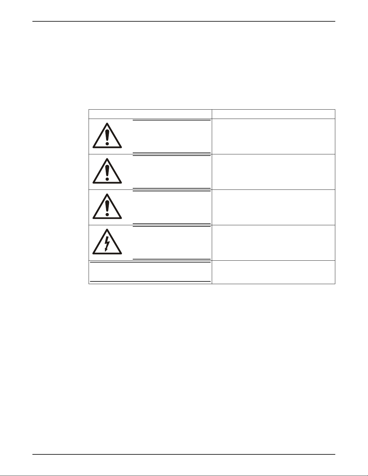
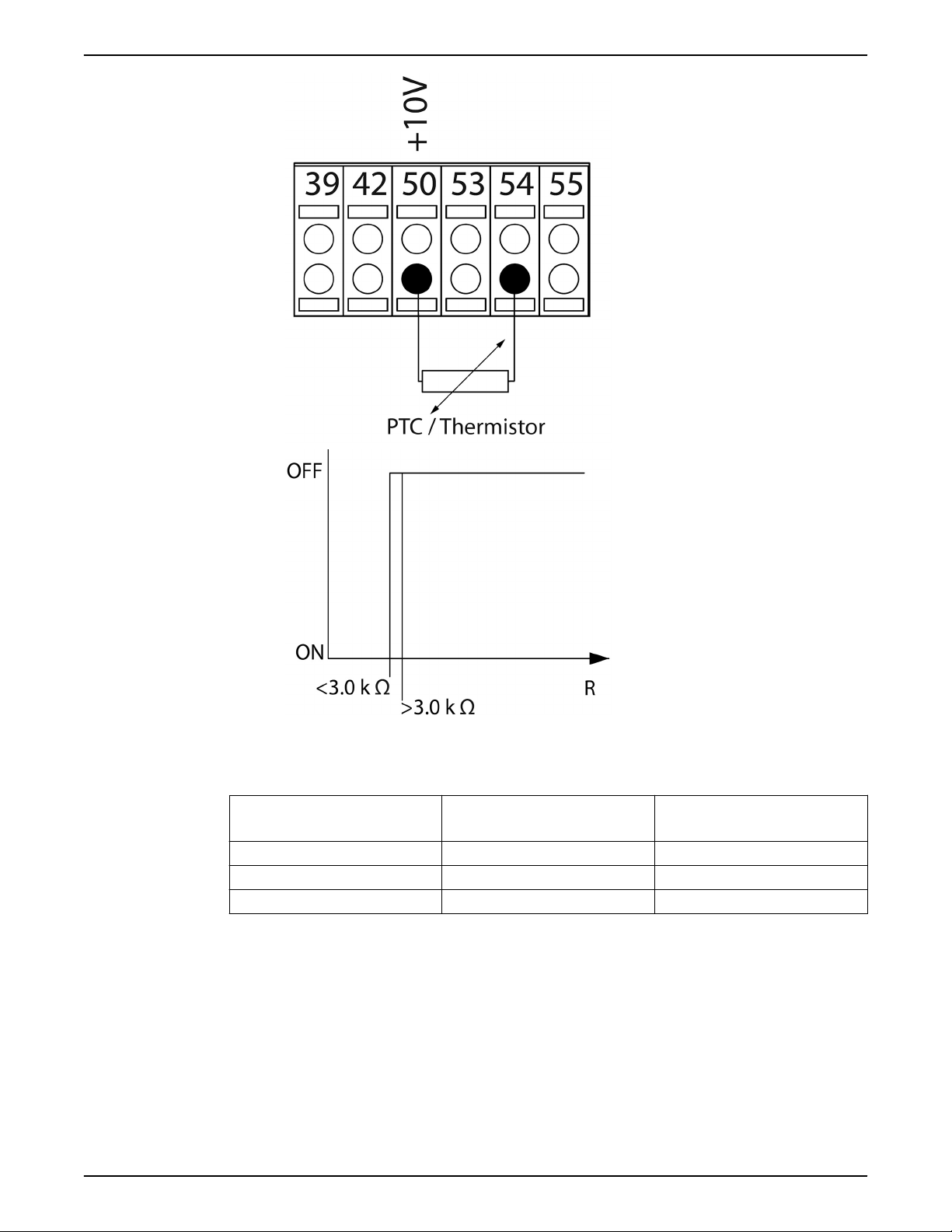
Motor thermal protection can also be achieved using an external thermistor. Set 1-90
Motor Thermal Protection to data value [2] Thermistor trip or data value [1] Thermistor
warning. Set 1-93 Thermistor Source to the input to which the thermistor is connected.
Refer to the examples below for wiring details.
The thermistor cut-out value is >3kΩ. Integrate a thermistor (PTC sensor) in the motor for
winding protection.
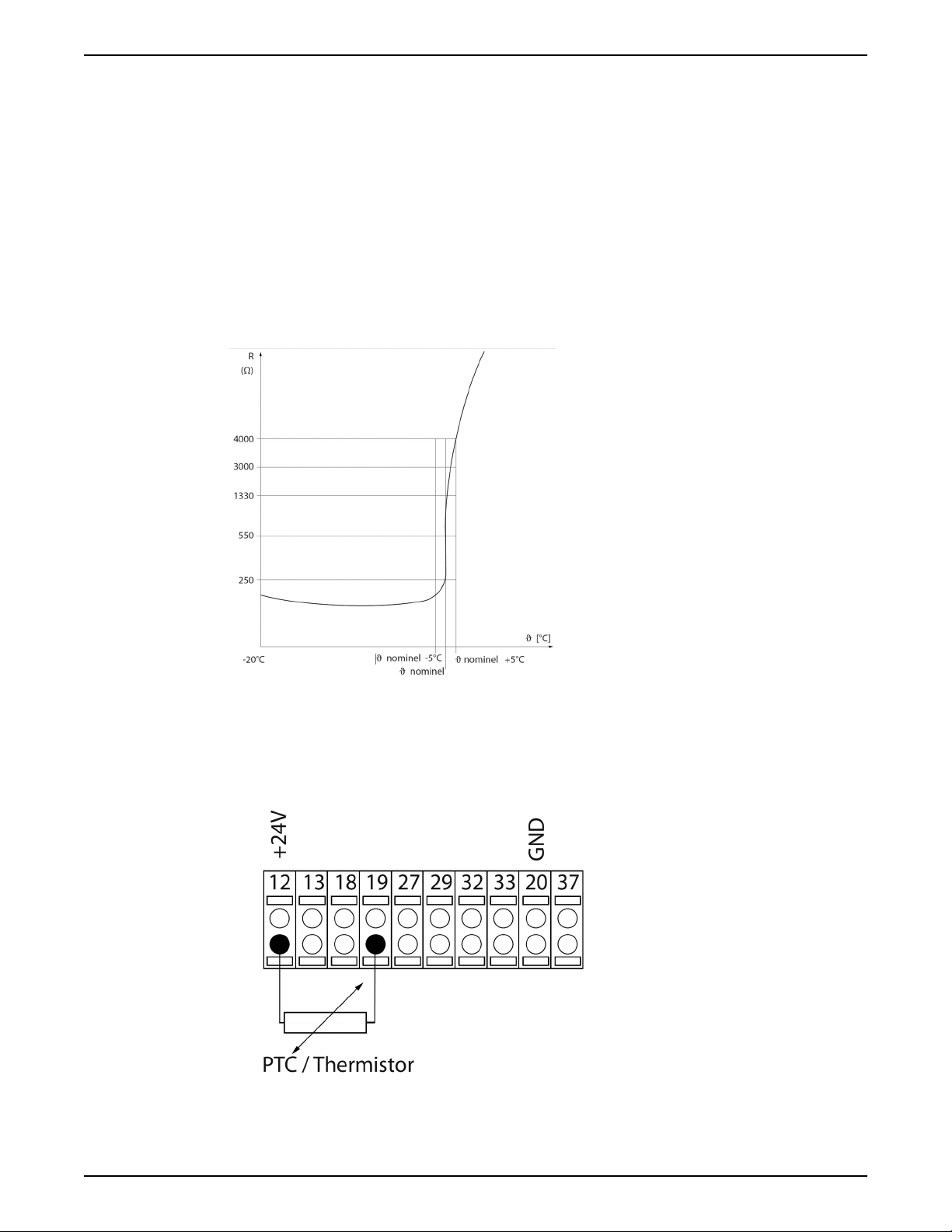
The following examples show various ways to connect the PTC/Thermistor to the drive.
• Using a digital input and the 24V as a power supply.
• Parameter set-up:
• Set 1-90 Motor Thermal Protection to Thermistor Trip [2]
• Set 1-93 Thermistor Source to Digital Input 19 [4]
Aquavar® Intelligent Pump Controller INSTRUCTION MANUAL 9
Product Description
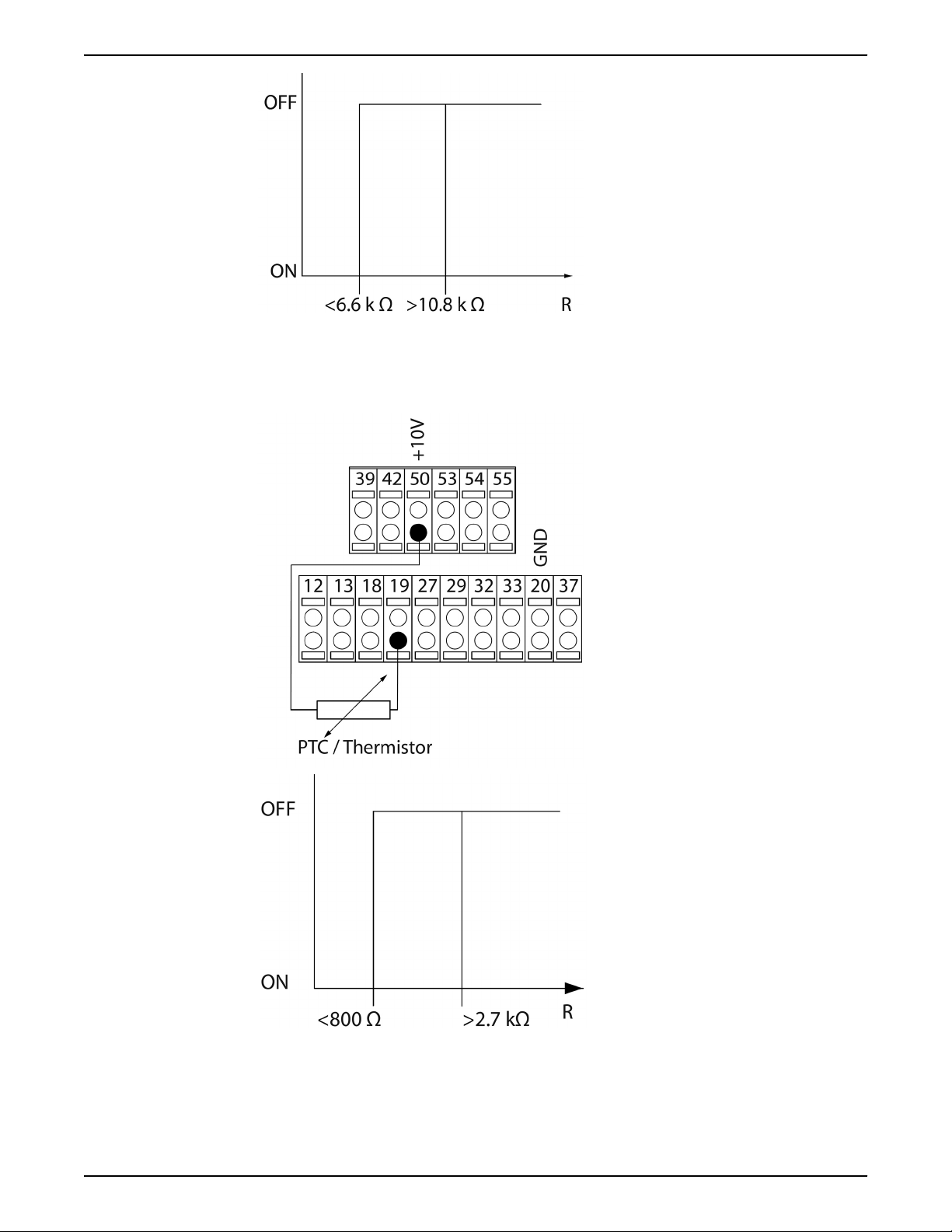
• Using a digital input and the 10V as a power supply.
• Parameter set-up:
• Set 1-90 Motor Thermal Protection to Thermistor Trip [2]
• Set 1-93 Thermistor Source to Digital Input 19 [4]
• Using an analog input and 10V as a power supply
• Parameter set-up:
• Set 1-90 Motor Thermal Protection to Thermistor Trip [2]
• Set 1-93 Thermistor Source to Analog Input 54 [2]. Do not use Analog Input
54 as any other feedback or reference source. Be sure to configure the analog
input configuration switches properly.
10 Aquavar® Intelligent Pump Controller INSTRUCTION MANUAL
Product Description
NOTE: Check that the chosen supply voltage follows the specification of the thermistor
element.
Summary
Input
Digital/analog
Supply Voltage V
Cut-out Values
Threshold
Cut-out Values
Digital 24 < 6.6kΩ — > 10.8kΩ
Digital 10 < 800kΩ — > 2.7kΩ
Analog 10 < 3.0kΩ — > 3.0kΩ
With the Torque limit feature the motor is protected from being overloaded independent
of the speed. With the ETR the motor is protected from being overheated and there is no
need for any further motor protection. That means when the motor is heated up the ETR
timer controls how long the motor can be operated at the high temperature before it is
stopped in order to prevent overheating. If the motor is overloaded without reaching the
temperature where the ETR turns off the motor, the torque limit will protect the motor
from being overloaded.
The ETR function is activated in 1-90 Motor Thermal Protection and is controlled in 4-16
Torque Limit Motor Mode. The time before the torque limit warning trips the drive is set in
14-25 Trip Delay at Torque Limit.
Aquavar® Intelligent Pump Controller INSTRUCTION MANUAL 11
A2 A3 A4 A5 B1 B2
B2 B3 C1 C2 C3 C4
Top and bottom mounting holes
Top and bottom mounting holes (B4+C3+C4 only)
IP20/21* IP20/21* IP55/66 IP55/66 IP21/66 IP21/55/66
IP20/21* IP20/21* IP21/55/66 IP21/55/66 IP20/21* IP220/21*
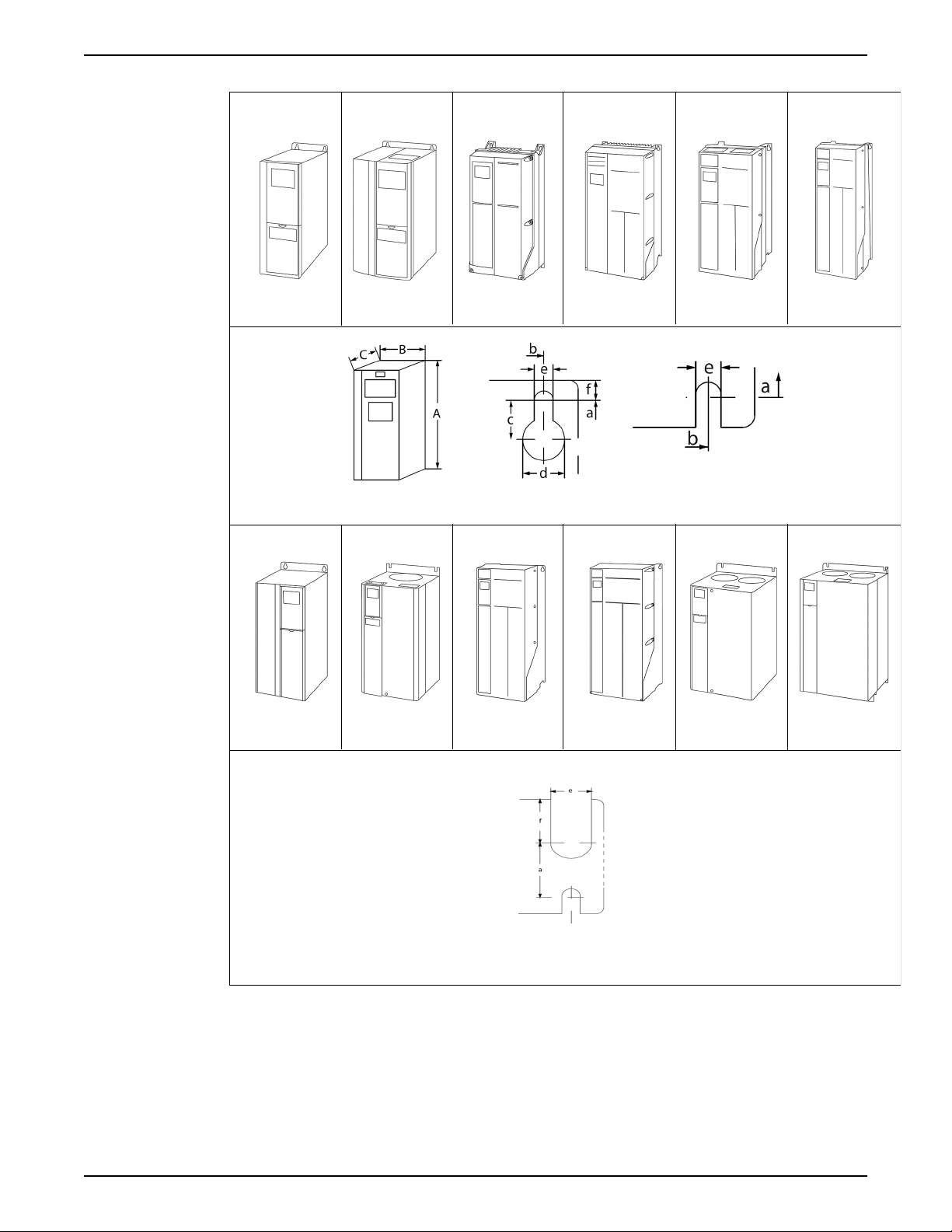
Product Description
Dimensions
12 Aquavar® Intelligent Pump Controller INSTRUCTION MANUAL

Frame Size
(HP):
208–230 V
380–460 V
1.5–3
1.5–5
575 V
Enclosure IP20
OPEN
Height in (mm)
Enclosure 9.69
(246)
with
decoupling
14.72
(374)
plate
Backplate 10.55
(268)
Distance
between
10.12
(257)
mounting
holes
Width in (mm)
Enclosure 3.54
(90)
Backplate 3.54
(90)
Distance
between
2.76
(70)
mounting
holes
Depth in (mm)
Without A/B
Option Card*
With A/B
Option Card*
8.07
(205)
8.66
(220)
Screw holes inches (mm)
Screw hole c 0.31
(8)
Screw hole d 0.43
(11)
Screw hole e 0.22
(5.5)
Screw hole f 0.35
(9)
Max. weight —
11 (5) 12
lb (kg)
Product Description
Mechanical Dimensions
A2 A3 A4 A5 B1 B2 B3 B4 C1 C2 C3 C4
5
7.5–10
1.5–10
1.5–3
1.5–5
1.5–5
1.5–10
1.5–10
7.5–15
15–25
15–25
20
30–40
15–40
7.5-15
15–25
15–25
20-25
30–50
30–50
25-40
50–75
50–75
50-60
100–
125
50–125
30-40
60–75
60–75
50-60
100–
125
100–
125
NEMA1IP20
OPEN
14.65
(372)
(246)
- 14.72
(374)
14.76
(375)
13.78
(350)
10.55
(268)
10.12
(257)
3.54
(90)
(130)
3.54
(90)
(130)
2.76
(70)
(110)
8.07
(205)
(205)
8.66
(220)
(220)
0.31
(8)
0.43
(11)
0.22
(5.5)
0.35
(9)
(5.5)15(6.8)16(7.3)
9.69
5.12
5.12
4.33
8.07
8.66
0.31
(8)
0.43
(11)
0.22
(5.5)
0.35
(9)
NEMA1NEMA
NEMA
14.65
(372)
15.35
(390)
12
4X
NEMA
12
NEMA
4X
16.54
(420)
NEMA
1
NEMA
12
NEMA
4X
18.90
(480)
NEMA
1
NEMA
12
NEMA
4X
25.59
(650)
- - - - - 16.5
14.76
(375)
13.78
(350)
(130)
(130)
(110)
(205)
(220)
5.12
5.12
4.33
8.07
8.66
0.31
(8)
0.43
(11)
0.22
(5.5)
0.35
(9)
15.35
(390)
15.79
(401)
7.87
(200)
7.87
(200)
6.73
(171)
6.89
(175)
6.89
(175)
0.32
(8.2)
0.47
(12)
0.26
(6.5)
0.24
(6)
16.54
(420)
15.83
(402)
9.53
(242)
9.53
(242)
8.46
(215)
7.87
(200)
7.87
(200)
0.32
(8.2)
0.47
(12)
0.26
(6.5)
0.35
(9)
18.90
(480)
17.87
(454)
9.53
(242)
9.53
(242)
8.27
(210)
10.24
(260)
10.24
(260)
0.47
(12)
0.75
(19)
0.35
(9)
0.35
(9)
25.59
(650)
24.57
(624)
9.53
(242)
9.53
(242)
8.27
(210)
10.24
(260)
10.24
(260)
0.47
(12)
0.75
(19)
0.35
(9)
0.35
(9)
22 (10) 31
(14.1)51(23.1)60(27.2)27(12.2)52(23.6)
IP20
OPEN
13.78
(350)
(419)
15.71
(399)
14.96
(380)
6.50
(165)
6.50
(165)
5.51
(140)
9.76
(248)
10.31
(262)
0.31
(8)
0.47
(12)
0.27
(6.8)
0.31
(7.9)
IP20
OPEN
18.11
(460)
23.43
(595)
20.47
(520)
19.49
(495)
9.09
(231)
9.09
(231)
7.87
(200)
9.53
(242)
9.53
(242)
- 0.47
- 0.75
0.33
(8.5)
0.59
(15)
NEMA
NEMA
NEMA
26.77
(680)
12
4X
NEMA
1
1
NEMA
12
NEMA
4X
30.31
(770)
- - 24.8
26.77
(680)
25.51
(648)
12.13
(308)
12.13
(308)
10.71
(272)
12.20
(310)
12.20
(310)
30.31
(770)
29.09
(739)
14.57
(370)
14.57
(370)
13.15
(334)
13.19
(335)
13.19
(335)
0.47
(12)
(12)
0.75
(19)
0.35
0.39
(9.8)
100
(45.4)
(9)
(19)
0.35
(9)
0.39
(9.8)
144
(65.3)78(35.4)
IP20
OPEN
19.29
(490)
(630)
21.65
(550)
20.51
(521)
12.13
(308)
12.13
(308)
10.63
(270)
13.11
(333)
13.11
(333)
- -
- -
0.33
(8.5)
0.67
(17)
IP20
OPEN
23.62
(600)
31.5
(800)
25.98
(660)
24.84
(631)
14.57
(370)
14.57
(370)
12.99
(330)
13.11
(333)
13.11
(333)
0.33
(8.5)
0.67
(17)
111
(50.4)
Aquavar® Intelligent Pump Controller INSTRUCTION MANUAL 13
Product Description
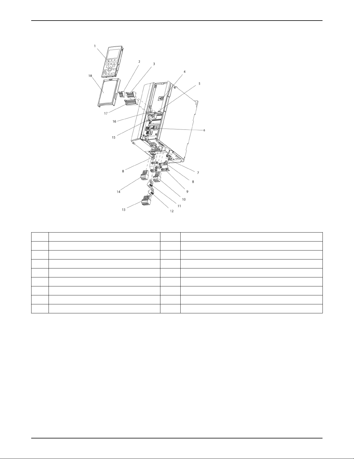
Frame size A description
Figure 1: Exploded view of Frame Size A
1 LCP 10 Motor output terminals 96 (U), 98 (W)
2 RS-485 serial bus connector (+68, 69) 11 Relay 2 (01, 02, 03)
3 Analog I/O connector 12 Relay 1 (04, 05, 06)
4 LCP input plug 13 Brake (-81, +82) and load sharing (-88, +89) terminals
5 Analog switches (A53), (A54) 14 Mains input terminals 91 (L1), 92 (L2), 93 (L3)
6 Cable strain relief/PE ground 15 USB connector
7 Decoupling plate 16 Serial bus terminal switch
8 Grounding clamp (PE) 17 Digital I/O and 24 V power supply
9 Shielded cable grounding clamp and strain relief 18 Control cable cover plate
14 Aquavar® Intelligent Pump Controller INSTRUCTION MANUAL
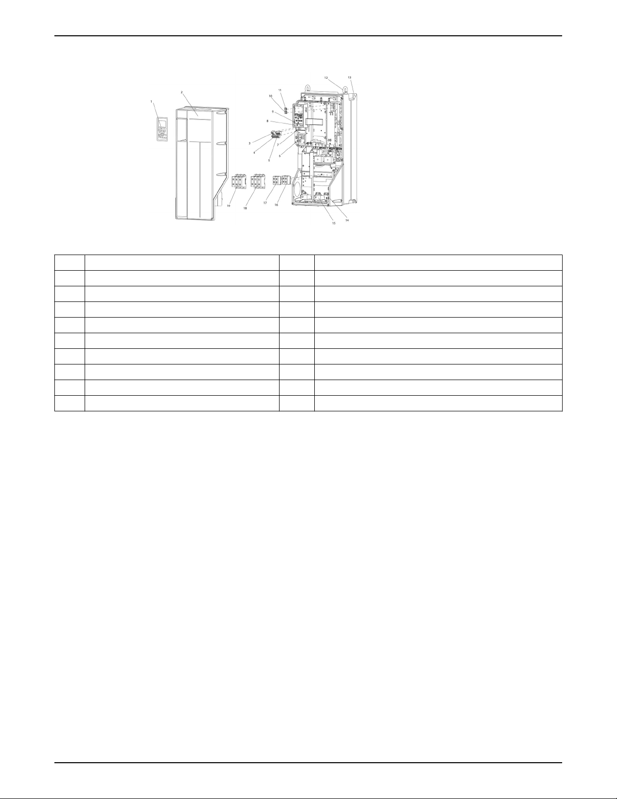
Frame sizes B and C description
Figure 2: Exploded view of Frame Sizes B and C
1 LCP 11 Relay 2 (04, 05, 06)
2 Cover 12 Lifting ring
3 RS-485 serial bus connector 13 Mounting slot
4 Digital I/O and 24 V power supply 14 Grounding clamp (PE)
5 Analog I/O connector 15 Cable strain relief / PE ground
6 Cable strain relief/PE ground 16 Brake terminal (-81, +82)
7 USB connector 17 Load sharing terminal (DC bus) (-88, +89)
8 Serial bus terminal switch 18 Motor output terminals 96 (U), 98 (W)
9 Analog switches (A53), (A54) 19 Mains input terminals 91 (L1), 92 (L2), 93 (L3)
10 Relay 1 (01, 02, 03)
Product Description
Aquavar® Intelligent Pump Controller INSTRUCTION MANUAL 15

Installation
Installation
Installation site checklist
• The frequency converter relies on the ambient air for cooling. Observe the limitations
on ambient air temperature for optimal operation.
• Ensure that the installation location has sufficient support strength to mount the
frequency converter.
• Keep the manual, drawings, and diagrams accessible for detailed installation and
operation instructions. It is important that the manual is available for equipment
operators.
• Locate equipment as near to the motor as possible. Keep motor cables as short as
possible. Check the motor characteristics for actual tolerances.
• For installations with motor leads longer than 50 feet, use the output filter option
to protect the motor.
• Ensure that the ingress protection rating of the frequency converter is suitable for the
installation environment. IP55 (Type 3R/12) or IP66 (Type 4) enclosures may be
necessary.
CAUTION:
Ingress protection. IP54, IP55 and IP66 ratings can only be guaranteed
if the unit is properly closed.
• Ensure all cable glands and unused holes for glands are properly
sealed.
• Ensure that the unit cover is properly closed.
Device damage through contamination. Do not leave the frequency
converter uncovered.
Frequency converter and motor pre-installation check list
• Compare the model number of the unit on the nameplate to what was ordered to
verify the proper equipment.
• Ensure each of the following are rated for same voltage:
• Mains (power)
• Frequency converter
• Motor
• Ensure that the frequency converter output current rating is equal to or greater than
motor service factor current for peak motor performance.
• Motor size and frequency converter power must match for proper overload
protection.
• If frequency converter rating is less than motor, full motor output cannot be
achieved.
16 Aquavar® Intelligent Pump Controller INSTRUCTION MANUAL
Electrical Installation
Precautions
WARNING:
• EQUIPMENT HAZARD. Rotating shafts and electrical equipment can be hazardous. All
electrical work must conform to national and local electrical codes. Installation, startup, and maintenance must be performed by trained and qualified personnel. Failure
to follow these guidelines could result in death or serious injury.
• FIRE HAZARD. Consult the Brake Design Guide IM257 for details on proper
installation of a brake resistor.
NOTICE:
WIRING ISOLATION. Run input power, motor wiring and control wiring in three separate
metallic conduits or use separated shielded cable for high frequency noise isolation.
Failure to isolate power, motor and control wiring could result in less than optimum
frequency converter and associated equipment performance.
Electrical Installation
For your safety comply with the following requirements:
• Electronic control equipment is connected to hazardous mains voltage. Extreme care
should be taken to protect against electrical hazards when applying power to the unit.
• Run motor cable from multiple frequency converters separately. Induced voltage can
charge equipment capacitors even with the equipment turned off and locked.
Overload and equipment protection:
• An electronically activated function within the frequency converter provides overload
protection in the motor. The overload calculates the level of increase to activate
timing for the trip (controller output stop) function. The higher the current draw, the
quicker the trip response. The overload provides Class 20 motor protection. See
Warnings and alarms section for details on the trip function.
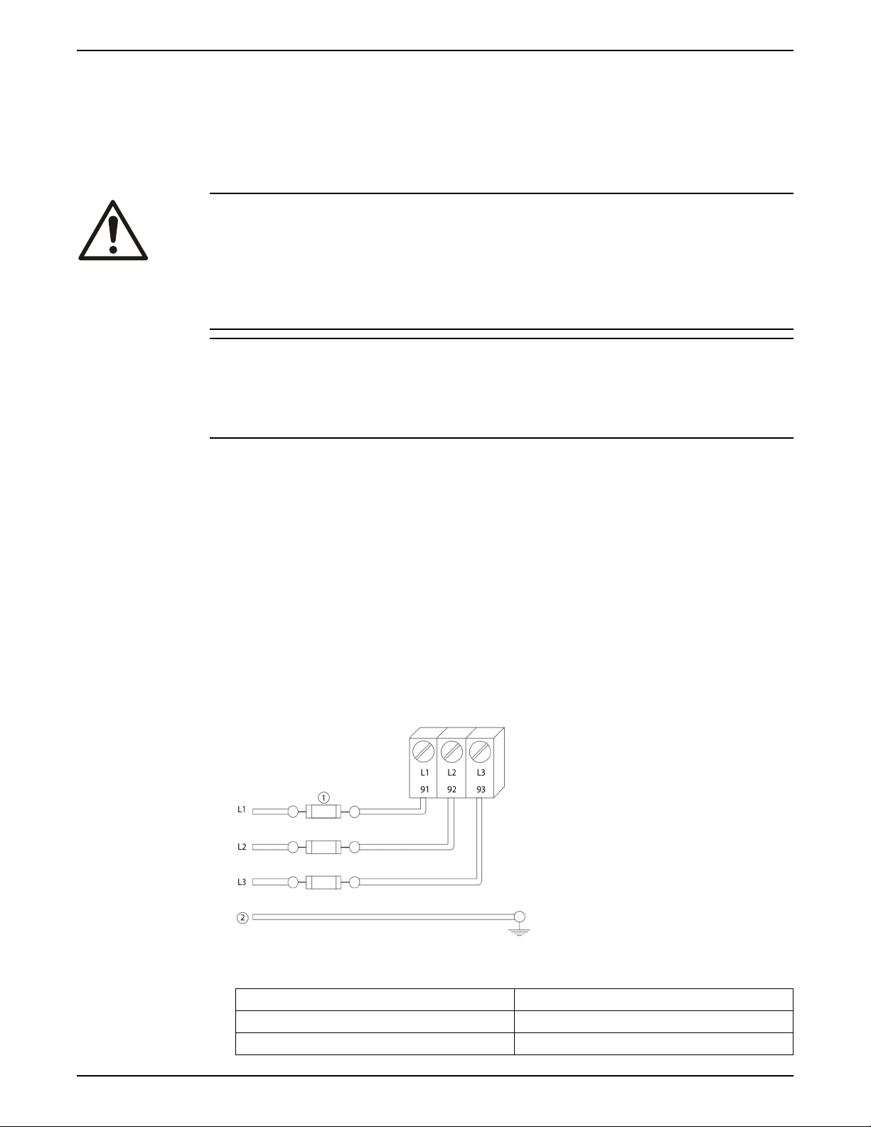
• All frequency converters must be provided with short-circuit and over-current
protection. Input fusing is required to provide this protection. If not factory supplied,
fuses must be provided by the installer as part of installations. See Fuse specifications
section for details.
Figure 3: Frequency converter fuses
Item Description
1 Fuses
2 Ground
Aquavar® Intelligent Pump Controller INSTRUCTION MANUAL 17

Electrical Installation
Wire type and ratings:
• All wiring must comply with local and national regulations regarding cross section and
ambient temperature requirements.
• It is recommended the all power connections be made with a minimum 75°C rated
copper wire.
• See Power-dependent specifications for recommended wire sizes.
Earth (grounding) requirements
WARNING:
For operator safety, it is important to ground the frequency converter properly in
accordance with national and local electrical codes as well as instructions contained within
this document. Ground currents are higher than 3.5 mA. Failure to ground the frequency
converter properly could result in death or serious injury.
NOTICE:
It is the responsibility of the user or certified electrical installer to ensure correct
grounding (earthing) of the equipment in accordance with national and local electrical
codes and standards.
• Follow all local and national electrical codes to ground electrical equipment properly.
• Proper protective grounding for equipment with ground currents higher the 3.5 mA
must be established. See the Leakage current (>3.5 mA) section for details.
• A dedicated ground wire is required for input power, motor power and control wiring.
• Use the clamps provided with the equipment for proper ground connections.
• Do not ground one frequency converter to another in a “daisy chain” fashion.
• Keep the ground wire connections as short as possible.
• Using high-strand wire to reduce electrical noise is recommended.
• Follow motor manufacturer wiring requirements.
Leakage current (>3.5 mA)
Follow national and local codes regarding protective earthing of equipment with a
leakage current > 3.5 mA. Frequency converter technology implies high frequency
switching at high power. This will generate a leakage current in the earth connection. A
fault current in the frequency converter at the output power terminals might contain a DC
component which can charge the filter capacitors and cause a transient earth current. The
earth leakage current depends on various system configurations including RFI filtering,
screened motor cables, and frequency converter power.
EN/EC61800–5–1 (Power Drive System Product standard) requires special care if the
leakage current exceeds 3.5 mA. Earth grounding must be reinforced in one of the
following ways:
• Earth ground wire of at least 8 AWG or 10 mm2.
• Two separate earth ground wires both complying with the dimensioning rules.
See EN60364–5–54 section 543.7 for further information.
Using GFCIs (RCDs)
Where Ground Fault Circuit Interrupters (GFCIs) and residual current devices (RCDs), also
know as earth leakage circuit breakers (ELCDs), are used, comply with the following:
• Use GFCIs (RCDs) of type B only which are capable of detecting AC and DC currents.
• Use GFCIs (RCDs) with an inrush delay to prevent faults due to transient earth
currents.
• Dimension GFCIs (RCDs) according to the system configuration and environmental
considerations.
Grounding using shielded cable
grounding (earthing) clamps are provided for motor wiring.
18 Aquavar® Intelligent Pump Controller INSTRUCTION MANUAL
Electrical Installation
Figure 4: Grounding with shielded cable
Basic electrical connection
This section contains detailed instructions for wiring the frequency converter. The
following tasks are described:
• Wiring the motor to the frequency converter output terminals
• Wiring the AC mains to the frequency converter input terminals
• Connecting control and serial communication wiring
• After power has been applied, checking input and motor power; programming
control terminals for their intended functions
Aquavar® Intelligent Pump Controller INSTRUCTION MANUAL 19
*
91 (L1)
92 (L2)
93 (L3)
PE
88 (-)
89 (+)
50 (+10 V OUT)
53 (A IN)
54 (A IN)
55 (COM A IN)
0/4-20 mA
12 (+24V OUT)
13 (+24V OUT)
18 (D IN)
20 (COM D IN)
15mA 200mA
(U) 96
(V) 97
(W) 98
(PE) 99
(COM A OUT) 39
(A OUT) 42
0/4-20 mA
03
0-10Vdc
+10Vdc
0-10Vdc
0/4-20 mA
240Vac, 2A
24Vdc
02
01
05
04
06
240Vac, 2A
24V (NPN)
0V (PNP)
0V (PNP)
24V (NPN)
19 (D IN)
24V (NPN)
0V (PNP)
27
24V
0V
(D IN/OUT)
0V (PNP)
24V (NPN)
(D IN/OUT)
0V
24V
29
24V (NPN)
0V (PNP)
0V (PNP)
24V (NPN)
33 (D IN)
32 (D IN)
1 2
ON
A53/S201
ON
21
A54/S202
ON=0-20mA
OFF=0-10V
95
400Vac, 2A
P 5-00
(R+) 82
(R-) 81
37 (D IN)
+ - + -
130BA544.12
(P RS-485) 68
(N RS-485) 69
(COM RS-485) 61
0V
5V
S801
RS-485
RS-485
21
ON
BUS TER./S801
3 Phase
power
input
DC bus
Switch Mode
Power Supply
Motor
Analog Output
Interface
relay1
relay2
ON=Terminated
OFF=Open
Brake
resistor
(NPN) = Sink
(PNP) = Source
Electrical Installation
Motor connection
20 Aquavar® Intelligent Pump Controller INSTRUCTION MANUAL
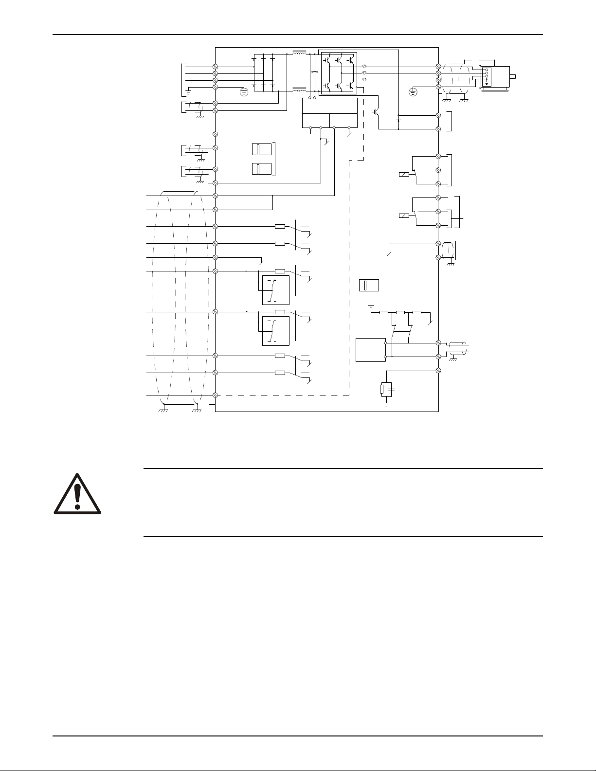
Figure 5: Basic electrical connection
WARNING:
INDUCED VOLTAGE. Run output motor cables from multiple frequency converters
separately. Induced voltage from output motor cables run together can charge
equipment capacitors even with the equipment turned off and locked out. Failure to run
output motor cables separately could result in death or serious injury.
Be sure the following are adhered to:
• For maximum wire sizes see Power-dependent Specifications.
• Comply with local and national electrical codes
• Motor wiring knockouts or access panels are provided at the base of IP21 and higher
(NEMA 1/12) units
• Do not install power factor correction capacitors between the frequency converter
and the motor
• Do not wire a starting or pole-changing device between the frequency converter and
the motor
• Connect the 3–phase motor wiring to terminals 96 (U), 97 (V), and 98 (W)
• Ground the cable in accordance with grounding instructions provided
• Torque terminals in accordance with the informations provided in Connection
tightening torques.
• Follow motor manufacturer wiring requirements
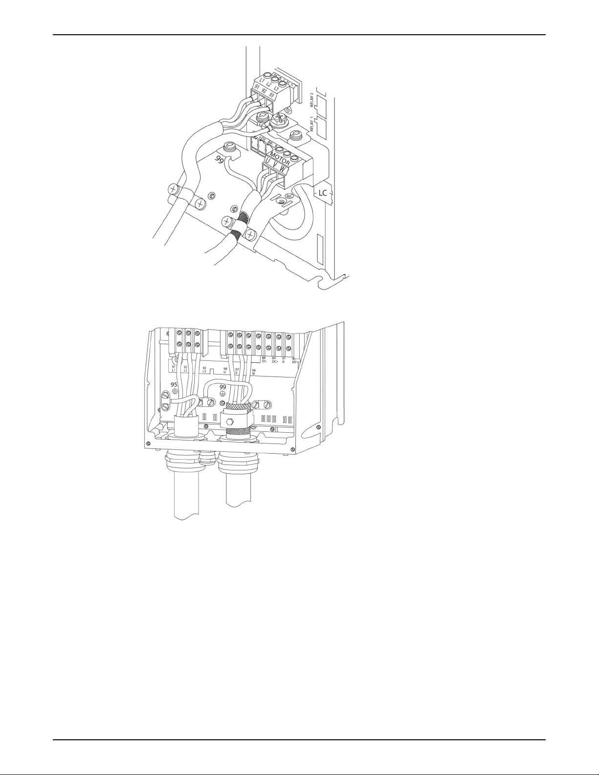
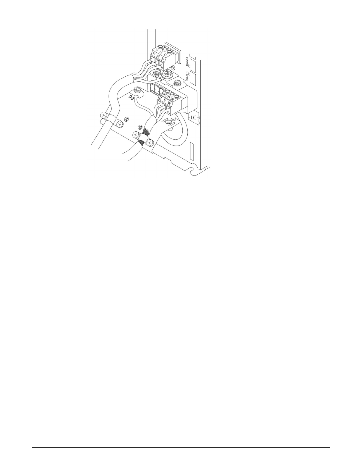
Figure 6: Motor, mains and earth wiring for frame size A
Electrical Installation
Figure 7: Motor, mains and earth wiring for frame sizes B, C, and D using shielded cable
Aquavar® Intelligent Pump Controller INSTRUCTION MANUAL 21
Electrical Installation
Figure 8: Motor, mains and earth wiring for frame sizes B, C and D
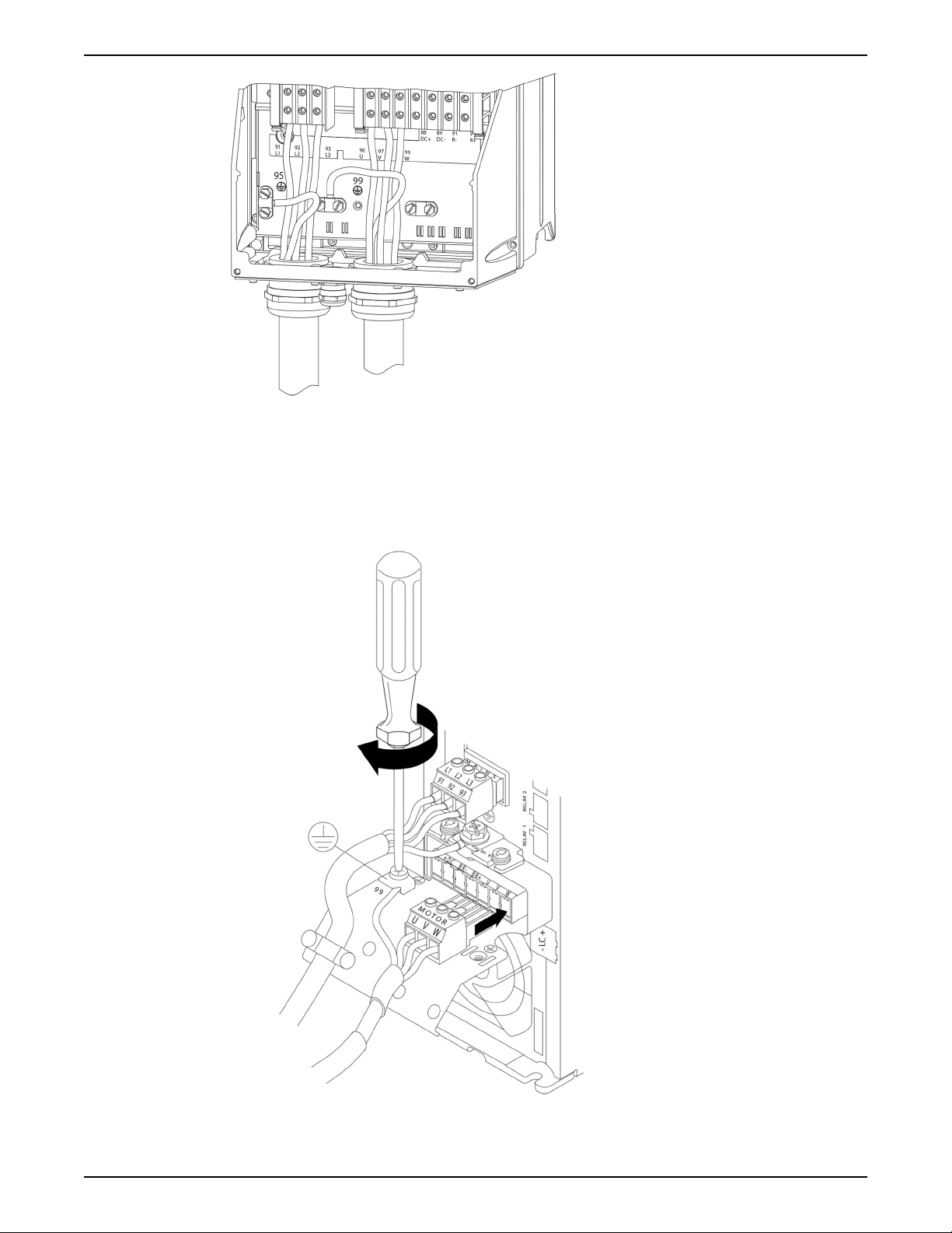
Motor connection for A2 and A3
Follow these drawings step by step for connecting the motor to the frequency converter.
1. Connect the motor earthwire to terminal 99, place motor U, V and W wires in plug and
tighten.
2. Mount cable clamp to ensure 360° connection between chassis and screen, note the
outer insulation of the motor cable is removed under the clamp.
22 Aquavar® Intelligent Pump Controller INSTRUCTION MANUAL
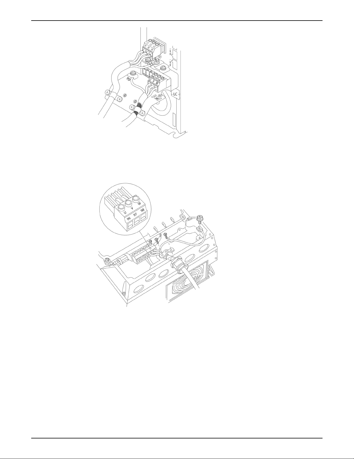
Motor connection for A4 and A5
1. Terminate the motor earth.
2. Place motor U, V and W wires in terminal and tighten.
3. Ensure that the outer insulation of the motor cable is removed under the EMC clamp.
Electrical Installation
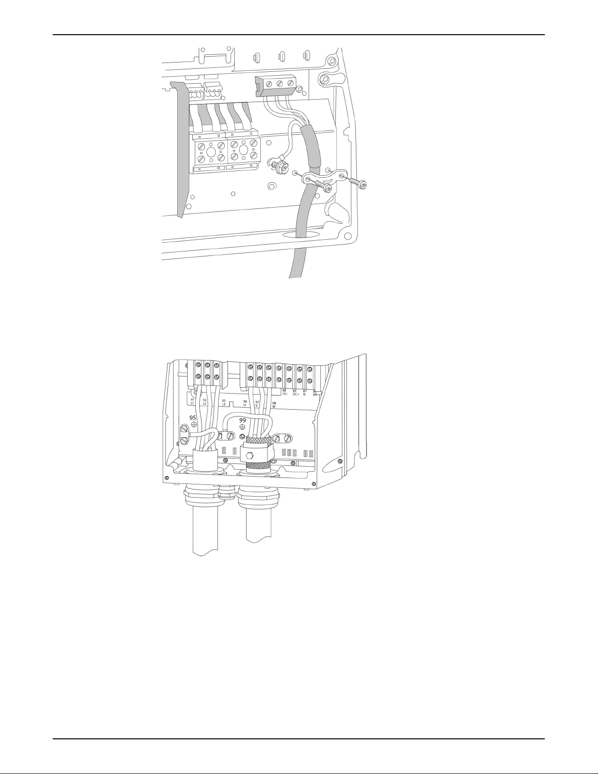
Motor connection for B1 and B2
1. Terminate the motor earth.
2. Place motor U, V and W wires in terminal and tighten.
3. Ensure that the outer insulation of the motor cable is removed under the EMC clamp.
Aquavar® Intelligent Pump Controller INSTRUCTION MANUAL 23
Electrical Installation
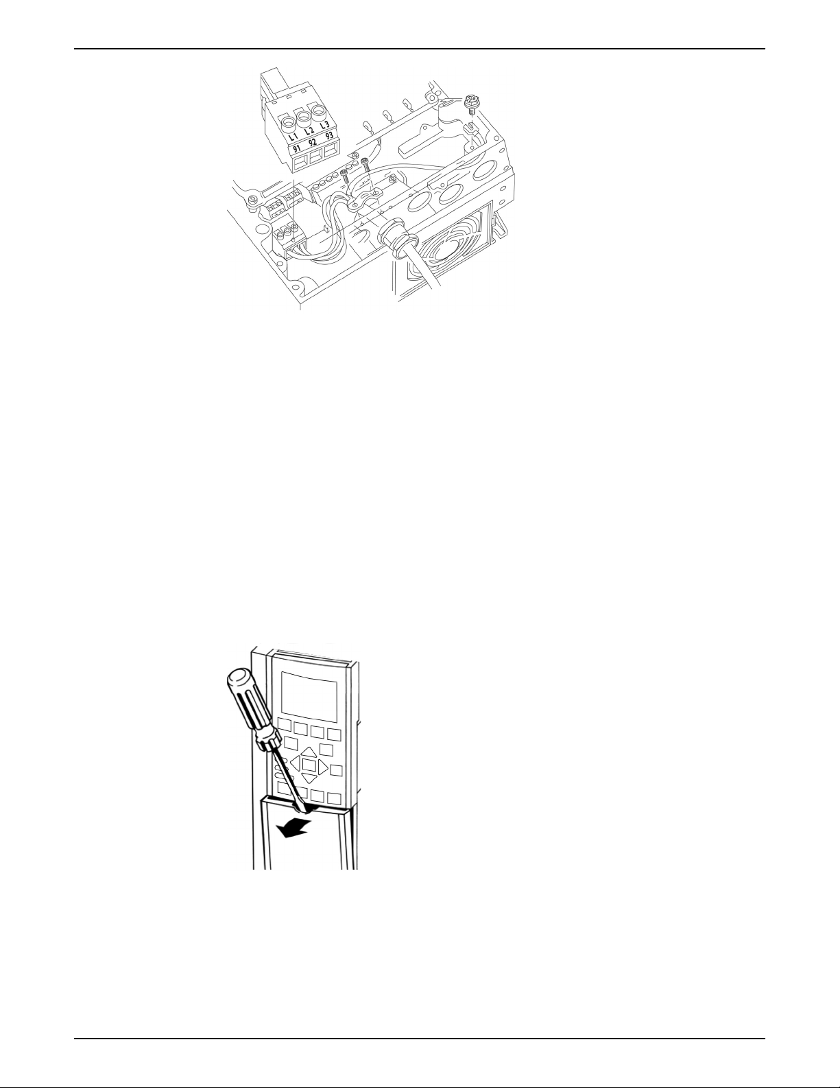
Motor connection for C1 and C2
1. Terminate the motor earth.
2. Place motor U, V and W wires in terminal and tighten.
3. Ensure that the outer insulation of the motor cable is removed under the EMC clamp.
AC mains connection
• Size wiring based upon the input current of the frequency converter. For maximum
wire sizes, see Power-dependent specifications section.
• Comply with local and national electrical codes for cable sizes.
• Connect 3–phase AC input power wiring to terminals L1, L2, and L3.
24 Aquavar® Intelligent Pump Controller INSTRUCTION MANUAL
Electrical Installation
• Depending on the configuration of the equipment, input power will be connected to
the mains input terminals or the input disconnect.
• Ground the cable in accordance with grounding instructions in Earth (Grounding)
Requirements.
• All frequency converters may be used with an isolated input source as well as with
ground reference power lines. When supplied from an isolated mains source (IT
mains or floating delta) or TT/TN-S mains with a grounded leg (grounded delta), set
14-50 RFI Filter to OFF. When off, the internal RFI filter capacitors between the chassis
and the intermediate circuit are isolated to avoid damage to the intermediate circuit
and to reduce earth capacity currents in accordance with IEC 61800-3.
Control wiring
• Isolate control wiring from high power components in the frequency converter.
• If the frequency converter is connected to a thermistor, for PELV isolation, optional
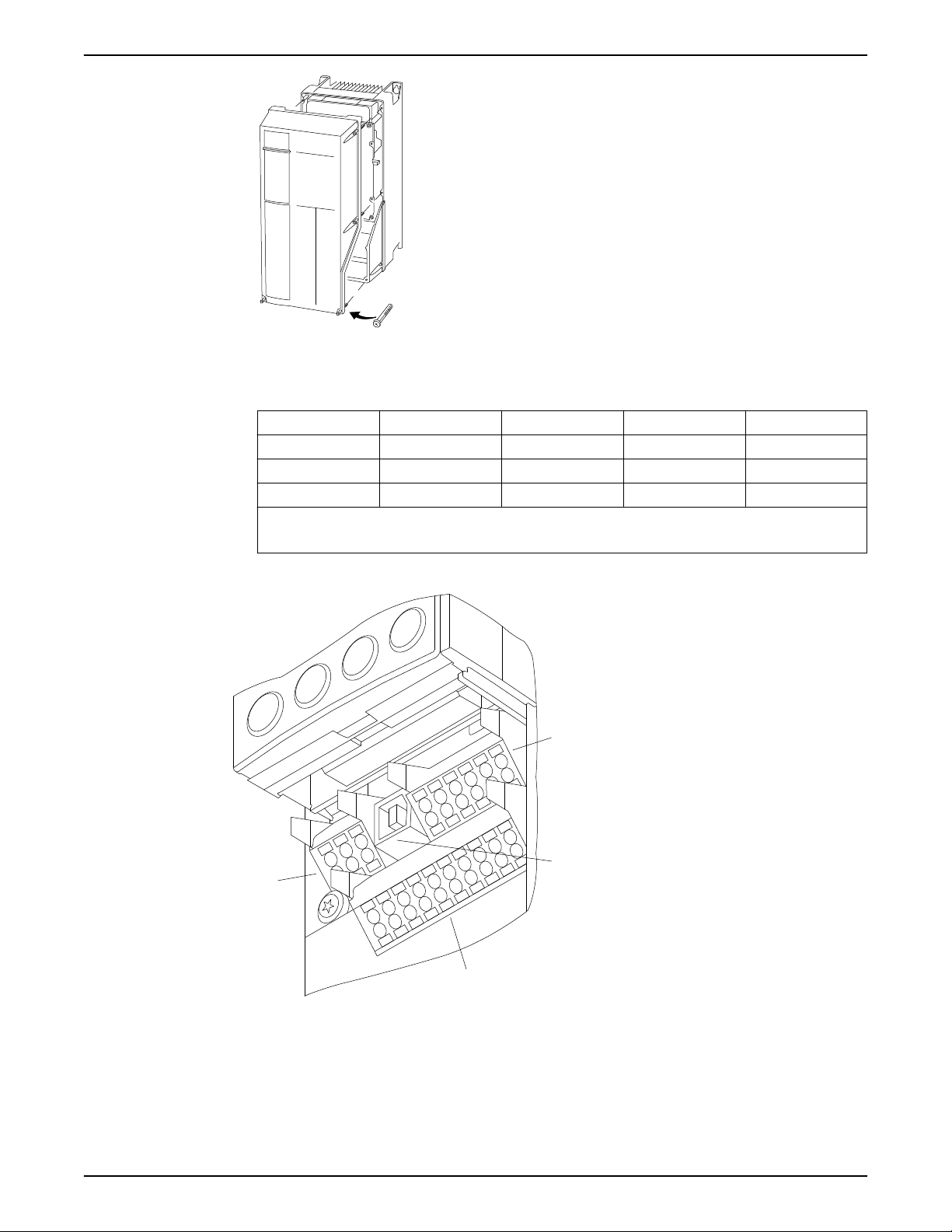
Control wiring access
• Remove access cover plate with a screwdriver.
• Remove front cover by loosening attaching screws.
thermistor control wiring must be reinforced/double insulated. A 24 V DC supply
voltage is recommended.
Figure 9: Control wiring access for A2, A3, B3, B4, C3, and C4 enclosures
Aquavar® Intelligent Pump Controller INSTRUCTION MANUAL 25
130BT334.10
1
4
2
3
130BA012.12
61
68
69
39
42
50
53
54
55
12
13
18
19
27
29
32
33
20
Electrical Installation
Figure 10: Control wiring access for A4, A5, B1, B2, C1, and C2 enclosures
Table 1: Tightening torques for covers (nM)
Frame IP20 Open IP21/Type 1 IP55/Type 12 IP66/Type 4X
A3/A4/A5 — — 2 2
B1/B2 — * 2.2 2.2
C1/C2/C3/C4 — * 2.2 2.2
* No screws to tighten
— Does not exist
Control terminal types
Figure 11: Control terminal locations
• Connector 1 provides four programmable digital inputs terminals, two additional
digital terminals programmable as either input or output, a 24 V DC terminal supply
voltage, and a common for optional customer supplied 24 V DC voltage.
• Connector 2 terminals (+)68 and (-)69 are for an RS-485 serial communications
connection.
26 Aquavar® Intelligent Pump Controller INSTRUCTION MANUAL

Electrical Installation
• Connector 3 provides two analog inputs, one analog output, 10 V DC supply voltage,
and commons for the inputs and output.
• Connector 4 is a USB port available for use with the frequency converter.
• Also provided are two Form C relay outputs that are in various locations depending
upon the frequency converter configuration and size.
• Some options available for ordering with the unit may provide additional terminals.
See the manual provided with the equipment option for details and configuration.
Table 2: Terminal descriptions
Terminal number Parameter number Default setting or
Description
function
Relay outputs 01, 02, 03 5–40 Relay 1 [160] No Alarm Form C Relay output.
04, 05, 06 5–40 Relay 2 [5] Running
Usable for AC or DC
voltages and either
resistive or inductive
loads. Refer to the
relay wiring section
for relay contact
current and voltage
ratings.
Aquavar® Intelligent Pump Controller INSTRUCTION MANUAL 27

Electrical Installation
Terminal number Parameter number Default setting or
Description
function
Digital I/O 12, 13 – +24V DC 24V DC supply
voltage. Maximum
output current is
200mA total for all
24V loads. Usable for
digital inputs and
external transducers.
18 5–10 [8] Start Start/Stop digital
input signal for the
drive. Connect input
to 24V to start. Open
the input to stop. This
is a required
connection.
19 5–11 [0] No Operation Unused digital input.
This input can be
configured for use as
a Pump Protect
Warning or Alarm
Input. See Pump
Protect section to
enable the Warning
or Alarm associated
with this input.
27 5–12 [0] No Operation Unused digital input.
This input can be
configured for use as
a Pump Protect
Warning or Alarm
Input. See Pump
Protect section to
enable the Warning
or Alarm associated
with this input.
29 5–13 [63] No Water/Loss of
Prime Restart (CMP3)
Selectable for digital
input or output.
Default configuration
is an output that is
configured for use as
a No Water/Loss of
Prime Restart signal.
Refer to the Pump
Protection section for
details.
32 5–14 [1] Reset Digital input.
Configured for use as
a Reset for the No
Water/Loss of Prime
Restart function. Refer
to the Pump
Protection section for
details.
33 5–15 [23] SP1/SP2 Select Digital input.
Configured for use as
a Setpoint 1/Setpoint
2 select (SP1/SP2).
20 – Common Common for digital
inputs and reference
for 24V supply
28 Aquavar® Intelligent Pump Controller INSTRUCTION MANUAL

Electrical Installation
Terminal number Parameter number Default setting or
function
Analog I/O 39 – AO Common Common for analog
42 6–50 [137] Speed 420 mA Analog output.
50 – +10V DC 10V DC analog supply
53 6–1* Transducer feedback Analog input 53.
54 6–2* Not Used Analog input 54
55 – AI Common Common for analog
Comm. 61 – Shield Connection Integrated RC filter for
68 8–3* + RS485 interface +
69 8–3* – RS485 interface –
Description
output
Default setting is
4-20mA signal (500Ω
max) based on motor
speed. Range is 0 to
max speed indicated
in parameter 4-14.
voltage. 15mA
maximum.
Default configuration
is 300 psi, 4-20mA
pressure transducer
input.
input
cable shield. ONLY for
connecting the shield
when experiencing
EMC problems.
Wiring to control terminals
Unplug terminal connectors
Control terminal connectors can be unplugged from the frequency converter for ease of
installation.
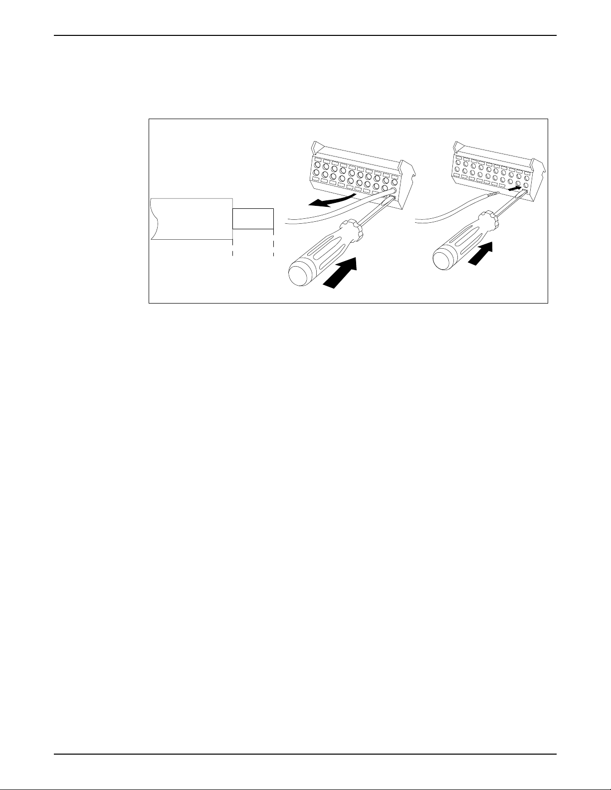
Control terminal connections
Connecting to the control terminals
1. To connect control wiring to the control terminals, do the following:
a. Strip the control wire back 9–10mm (0.35–0.40 in)
b. Insert a screwdriver (0.4 x 2.5 mm) in the rectangular hole.
Aquavar® Intelligent Pump Controller INSTRUCTION MANUAL 29
130BA150.10
9 - 10 mm
(0.37 in)
130BT311.10
130BT312.10
1. 2. 3.
Electrical Installation
c. Insert the cable in the adjacent circular hole.
d. Remove the screwdriver. The wire is now mounted to the terminal.
2. To remove the wire from the terminal:
a. Insert a screwdriver (0.4 x 2.5 mm) in the rectangular hole.
b. Pull out the cable.
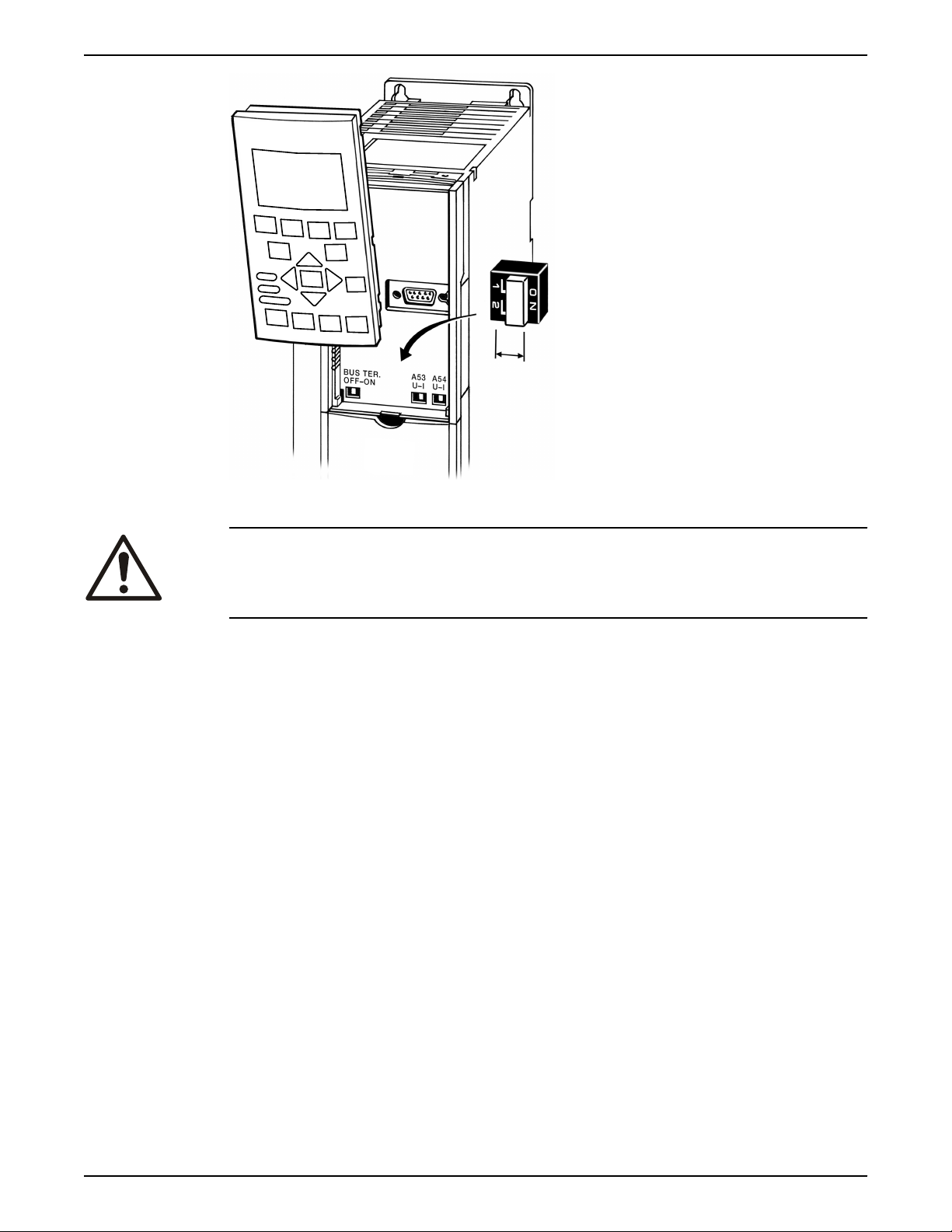
Analog input
Figure 12: Connecting and disconnecting control wiring
configuration
If an analog input is used, the analog input configuration switches must be set properly.
To set the configuration switches, remove the local control panel and set the appropriate
switch as required.
• Remove power from the controller before changing the analog input configuration
switches.
• To configure the analog input as a voltage input, set the configuration switch to U.
• Set the configuration switch to I to enable the input as a current input.
• Switch A53 is used to configure analog input 53.
• Switch A54 is used to configure analog input 54.
30 Aquavar® Intelligent Pump Controller INSTRUCTION MANUAL
130BT310.10
Electrical Installation
Figure 13: Configuration switch location
WARNING:
Some option cards available for the unit may cover these switches and must be removed
to change switch settings. Always remove power to the unit before removing option
cards.
Control terminal functions
Frequency converter functions are commanded by receiving control input signals.
• Each terminal must be programmed for the function it will be supporting in the
parameters associated with that terminal.
• It is important to confirm that the control terminal is programmed for the correct
function. See the Local control panel section for detail on accessing parameters and
frequency converter section for details on programming.
• The default terminal programming is intended to initiate frequency converter
functioning in a single pump, constant pressure operating more.
Analog input 53
The default operating mode of the frequency converter is Single Pump, constant pressure
mode. In this mode a feedback signal from a transducer, PLC or other device is required
on Analog Input 53 (AI 53). The default settings for AI 53 allow the use of a 300psi,
4-20mA pressure transducer.
When using the supplied pressure transducer:
1. Connect the feedback (white wire) from the transducer cable to AI 53
2. Connect the power wire (brown wire) to terminal 12 or 13 (24V dc)
3. In cases where the transducer is mounted on ungrounded piping, connect the drain
(bare wire) to the spring loaded cable strain relief clamps found below the control
terminals.
Jumper terminals 12 and 18
The frequency converter has been
To apply a start signal connect the device used to control starting of the drive or a jumper
Aquavar® Intelligent Pump Controller INSTRUCTION MANUAL 31
configured to require a start command on terminal 18.
Electrical Installation
wire between terminals 18 (DI 18, parameter 5-10) and 12 (24V dc). A start command is
given to the controller when terminal 18 is connected to 24V.
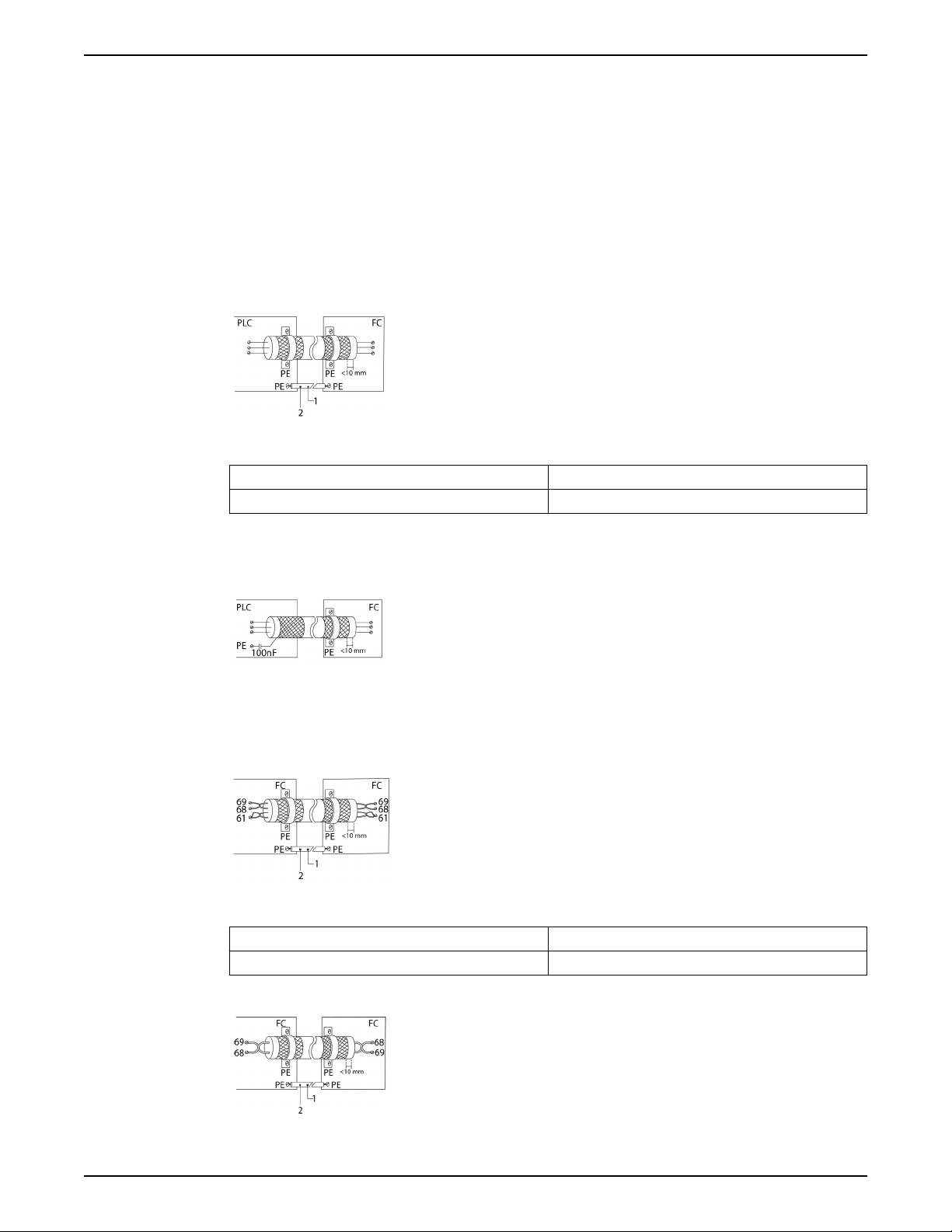
Using screened control cables
Correct screening
The preferred method in most cases is to secure control and serial communication cables
with screening clamps provided at both ends to ensure best possible high frequency
cable contact.
If the earth potential between the frequency converter and the PLC is different, electric
noise may occur that will disturb the entire system. Solve this problem by fitting an
equalizing cable next to the control cable. Minimum cable cross section: 6 AWG or 16
mm2.
Figure 14: Correct screening
1 Min. 6 AWG or 16 mm
2 Equalizing cable
50/60 Hz ground loops
With very long control cables, ground loops may occur. To eliminate ground loops,
connect one end of the screen-to-ground with a 100 nF capacitor (keeping leads short).
Figure 15: 50/60 Hz ground loops
Avoid EMC noise on serial communication
This terminal is connected to earth via an internal RC link. Use twisted-pair cables to
reduce interference between conductors.
Figure 16: Twisted-pair cables
2
1 Min. 6 AWG or 16 mm
2
2 Equalizing cable
Alternatively, the connection to terminal 61 can be omitted:
Figure 17: Twisted-pair cables without terminal 61
32 Aquavar® Intelligent Pump Controller INSTRUCTION MANUAL
Electrical Installation
1 Min. 6 AWG or 16 mm
2 Equalizing cable
Serial communication
RS-485 is two-wire bus interface compatible with multi-drop network topology. For
example, nodes can be connected as a bus, or via drop cables from a common trunk line.
A total of 32 nodes can be connected to one network segment. Repeaters divide network
segments. Note that each repeater functions as a node within the segment in which it is
installed. Each node connected within a given network must have a unique node address,
across all segments. Terminate each segment at both ends, using either the termination
switch (BUS TER./S801) of the frequency converters or a biased termination resistor
network. Always use screened twisted pair (STP) cable for bus cabling, and always follow
good common installation practice.
Low-impedence ground (earth) connection of the screen at every node is important,
including at high frequencies. Thus, connect a large surface of the screen to ground
(earth) , for example with a cable clamp or a conductive cable gland. It may be necessary
to apply potential-equalizing cables to maintain the same ground (earth) potential
throughout the network. Particularly in installations with long cables.
To prevent impedence mismatch, always use the same type of cable throughout the entire
network. When connecting a motor to the frequency converter, always use screened
motor cable.
Table 3: Cable information
2
Cable Screened twisted pair (STP)
Impedence 120 Ω
Max. cable length [m] 1200 including drop lines
Common terminal wiring configurations
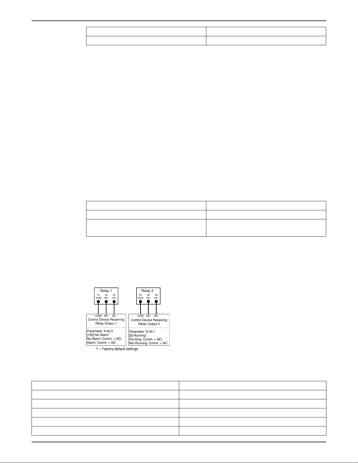
Relay wiring
Each controller has two programmable form C relay outputs. The relay terminals are
located in various locations on the controller depending on the frame size. NOTE: Relay
functions can be enabled using the Start-Up Genie.
Figure 18: Relay terminal wiring
Table 4: Relay terminal ratings
500 station-to-station
Programmable relay outputs 2
Relay 01 Terminal number 1–3 (break), 1–2 (make)
Maximum terminal load (AC-1)1 on 1–3 (NC), 1–2 (NO) (Resistive load) 240 V AC, 2A
Maximum terminal load (AC-15)1 (Inductive load @ cosφ 0.4) 240 V AC, 0.2A
Maximum terminal load (DC-1)1 on 1–2 (NO), 1–3 (NC) (Resistive load) 60 V DC, 1A
Maximum terminal load (DC-13)1 (Inductive load) 24 V DC, 0.1A
Aquavar® Intelligent Pump Controller INSTRUCTION MANUAL 33
Electrical Installation
Relay 02 Terminal number 4–6 (break), 4–5 (make)
Maximum terminal load (AC-2)1 on 4–5 (NO) (resistive load)
2,3
400 V AC, 2A
Maximum terminal load (AC-15)1 (Inductive load @ cosφ 0.4) 240 V AC, 0.2A
Maximum terminal load (DC-1)1 on 4–5 (NO) (Resistive load) 80 V DC, 2A
Maximum terminal load (DC-13)1 on 4–5 (NO) (Inductive load) 24 V DC, 0.1A
Maximum terminal load (AC-1)1 on 4–6 (NC) (Resistive load) 240 V AC, 2A
Maximum terminal load (AC-15)1 on 4–6 (NC) (Inductive load @ cosφ
240 V AC, 0.2A
0.4)
Maximum terminal load (DC-1)1 on 4–6 (NC) (Resistive load) 50 V DC, 2A
Maximum terminal load (DC-13)1 on 4–6 (NC) (Inductive load) 24 V DC, 0.1A
Minimum terminal load on 1–3 (NC), 1–2 (NO), 4–6 (NC), 4–5 (NO) 24 V DC 10mA, 24 V AC 20mA
Environment according to EN 60664–1 overvoltage category III/pollution degree 2
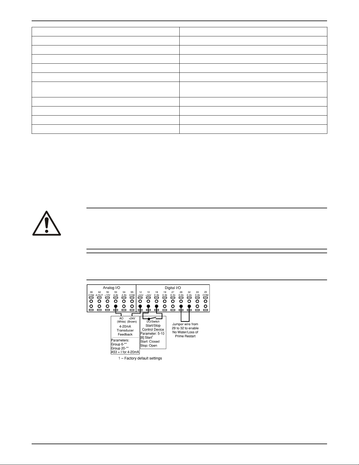
Wiring for factory default setup
This configuration utilizes the controller factory default settings for I/O. The factory default
settings are configured for a single pump, constant pressure application with a 300 psi,
4-20mA pressure transducer wired to AI 53. A jumper wire is needed between terminals
29 and 32 to enable the No Water/Loss of Prime Restart function. A Start signal is applied
on Digital Input 18. The controller will receive a Start command when DI 18 is connected
to 24V. There are no parameters that need to be adjusted for this configuration. Refer to
Commissioning section for details on configuring the controller and changing application
settings.
Pump protect
CAUTION:
When a Start (Closed) signal is present on DI18, the controller can start the pump/motor
at any time without warning. Set DI18 to Stop (Open) or press the [Off] operation key
before using the Genie. Apply the Start signal to the controller only when pump/motor
operation is desired.
NOTICE:
The factory default settings are configured to require a start signal wired to DI18 as shown
below.
Figure 19: Required terminal connections for use with factory default settings
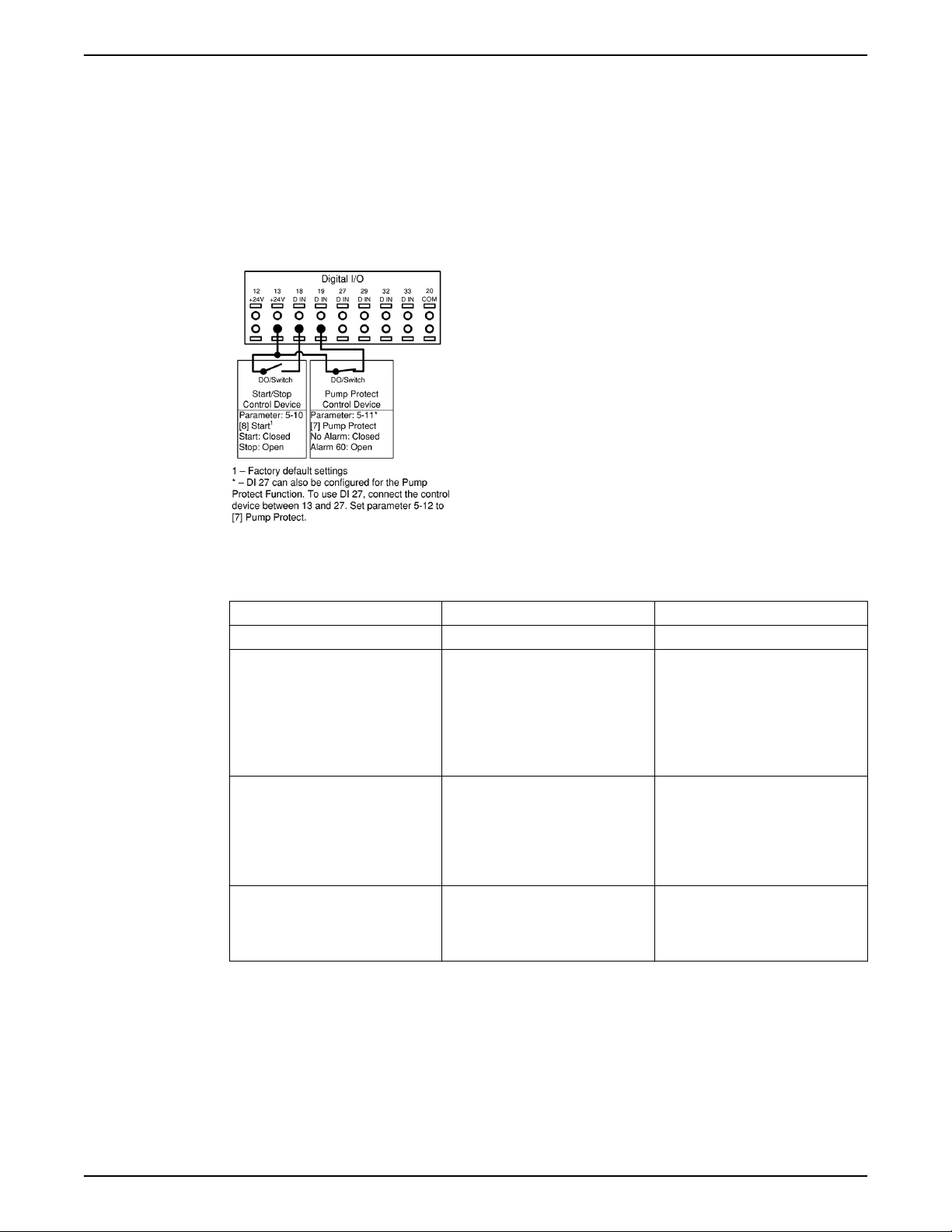
A Pump Protect function can be used to turn off the controller and issue an alarm (Pump
Protect Alarm 60) when system pressures, temperatures, levels, etc. are outside of the
normal operating range for the system. The Pump Protect function can be configured on
digital input 19 and digital input 27. These inputs can be controlled by an external device
such as a suction pressure switch, an over pressure switch, a temperature switch, a
differential pressure switch, etc. The device chosen should be normally closed. The
[22-00] Pump Protect Delay parameter can be configured to delay the onset of the Pump
34 Aquavar® Intelligent Pump Controller INSTRUCTION MANUAL
Electrical Installation
Protect Alarm to prevent nuisance tripping. When the input is disconnected from the 24V
supply, the delay timer will start. If the input remains disconnected for the time indicated
in [22-00] Pump Protect Delay, the controller stops the motor and issues Alarm 60 Pump
Protect. If a Pump Protect Alarm is issued, the controller will attempt to restart if the
[14-20] Reset Mode parameter and the [14-21] Automatic Restart Time parameter are set
to allow automatic restarting. To prevent an automatic restart set the [14-20] Reset Mode
to Manual Reset. Note that the [14-20] Reset Mode parameter affects all other Alarms that
are not listed as a Trip Lock Alarm. Refer to the Warnings/Alarm Messages section for
details.
NOTE: This function can be enabled using the Start-Up Genie.
Figure 20: Connections for adding Pump Protect
Table 5: Parameter settings for enabling a Pump Protect Alarm on DI19
Parameter number Parameter description Set to
5–11* Terminal 19 Digital Input Pump Protect
22–00 Pump Protect Delay Set to the desired delay time. If set to
10 seconds, the Pump Protect Alarm
will be issued 10 seconds after the
input is disconnected from 24V. The
input must remain disconnected for
the entire delay time for the alarm to
be issued.
14–20 Reset Mode Set to the desired number of
automatic resets. If a fault occurs
more than this setting, a manual
reset is required. Set to Manual Reset
if no resets are allowed. Default
setting is: Automatic reset x 3.
14–21 Automatic Restart Time This is the time between when an
alarm/warning is issued and when
the controller attempts the next
restart. Default setting is 30 seconds.
* To configure DI 27, set 5–12 to Pump Protect.
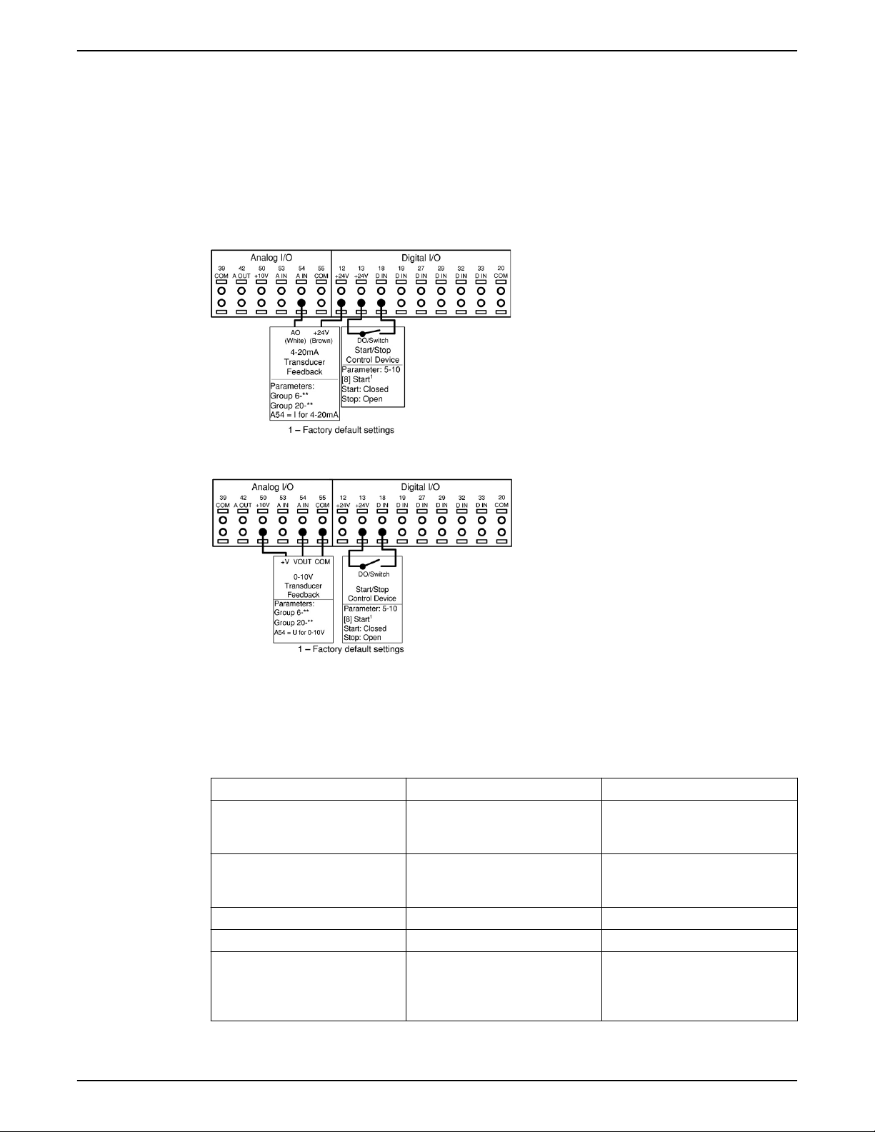
Configuring an additional transducer feedback
An additional transducer can be added to the system to work with closed loop control or
for external monitoring. The additional transducer can be either a voltage output or
current output transducer. The additional transducer can be added to the unused analog
input (AI 53 or AI 54). The wiring below shows the required connections for an additional
transducer on AI 54.
Aquavar® Intelligent Pump Controller INSTRUCTION MANUAL 35
Electrical Installation
A common use of two pressure transducer feedback signals is to take the difference
between the signals to create a differential pressure transducer. To implement a
differential pressure transducer with 2 pressure transducers, set parameter [20-20]
Feedback Function to Difference. The controller will calculate the feedback value as
Feedback 1 Source [20-00] – Feedback 2 Source [20-03]. Be sure to set all unused
feedback sources to No Function (parameters 20-00, 20-03 or 20-06). The parameter
listing that follows shows how to configure the additional transducer.
• Analog inputs can be configured using the Start-Up Genie.
• Be sure to properly set the analog input configuration switch prior to using the analog
input. Refer to the Analog input configuration (Switches A53 and A54) for details.
Figure 21: Connections for adding 4–20 mA transducer feedback to AI 54
Figure 22: Connections for adding 0–10 V transducer feedback to AI 54
In order to set up the controller for closed loop control based on the feedback from an
external transducer, set the following parameters:
Table 6: Parameter settings to enable an additional transducer on AI 54
Parameter Number Parameter Description Set To
6-24* Terminal 54 Low Ref./Feedb. Value Minimum transducer feedback value.
For example, for a 0-300psi
transducer, set to 0.
6-25* Terminal 54 High Ref./Feedb. Value Maximum transducer feedback
value. For example, for a 300psi
transducer, set to 300.
6-27* Terminal 54 Sensor Fault Enabled
20-03 Feedback 2 Source Analog Input 54*
20-05 Feedback 2 Source Unit Units for the second feedback source.
For a differential pressure transducer,
use the same units as found in 20-02,
psi is default
36 Aquavar® Intelligent Pump Controller INSTRUCTION MANUAL

Electrical Installation
Parameter Number Parameter Description Set To
20-12 Reference/Feedback Unit Select as appropriate for application.
For example, set to psi when using
pressure feedback.
20-13 Minimum Reference/Feedback Minimum transducer feedback value.
For example, for a 0-300psi
transducer, set to 0.
20-14 Maximum Reference/Feedback Maximum transducer feedback
value. For example, for a 300psi
transducer, set to 300.
* To use AI 53, configure parameters 6-14, 6-15, 6-17
Table 7: Parameters for an additional transducer used for monitoring
Parameter number Description Set to
0-24 Display Line 3 Large Ext. 1 Feedback [Unit]
21-14 Ext. 1 Feedback Source Analog Input 54*
21-10 Ext. 1 Ref./Feedback Unit Select as appropriate for application.
For example, set to psi when using a
pressure transducer.
21-11 Ext. 1 Minimum Reference Minimum transducer feedback value.
For example, for a 0-300psi
transducer, set to 0 psi.
21-12 Ext. 1 Maximum Reference Maximum transducer feedback
value. For example, for a 300 psi DP
transducer, set to 300 psi.
6-24* Terminal 54 Low Ref./Feedb. Value Minimum transducer feedback value.
For example, for a 0-300 psi
transducer, set to 0.
6-25* Terminal 54 High Ref./Feedb. Value Maximum transducer feedback
value. For example, for a 300 psi
transducer, set to 300.
6-27* Terminal 54 Sensor Fault Disabled
* To use AI 53, configure parameters 6-14, 6-15, 6-17 and set 21-14 to Analog Input 53
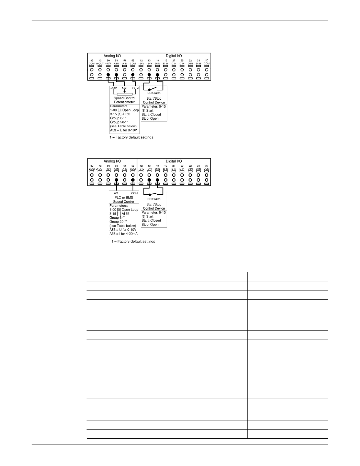
Speed control through an analog input
The controller can be configured for speed control through an analog input. The
controlling source can be either an external control device such as a PLC, BMS (building
management system) or potentiometer. The output from the external control device can
be either a voltage or current output signal. Be sure to set the analog input configuration
Aquavar® Intelligent Pump Controller INSTRUCTION MANUAL 37
Electrical Installation
switches based on the type of output signal. The diagrams below show the connections
for an external speed command.
• Speed control mode can be configured using the Start-Up Genie.
Figure 23: Connections for speed control with external potentiometer
Figure 24: Connections for speed control with PLC or BMS
Table 8: Parameters for speed control from external potentiometer, PLC or BMS
Parameter number Description Set to
1-00 Configuration Mode Open Loop
3-15 Reference 1 Source Analog Input 53
3-02 Minimum Reference Set to value corresponding to desired
speed at the minimum reference
3-03 Maximum Reference Set to value corresponding to desired
speed at the maximum reference
3-15 Reference 1 Source Analog Input 53***
6-10* Terminal 53 Low Voltage* 0 V
6-11* Terminal 53 High Voltage* 10 V
6-12** Terminal 53 Low Current** 4 mA
6-13** Terminal 53 High Current** 20 mA
6-14 Terminal 53 Low Ref./Feedb. Value Set to value corresponding to the
commanded speed at the low
voltage/current.
6-15 Terminal 53 High Ref./Feedb. Value Set to value corresponding to the
commanded speed at the high
voltage/current.
6-17 Terminal 53 Sensor Fault Disabled
2000 Feedback 1 Source No Function
38 Aquavar® Intelligent Pump Controller INSTRUCTION MANUAL
* Set switch A53 = U, parameters 612 and 613 are hidden when A53 = U.
** Set switch A53 = I, parameters 610 and 611 are hidden when A53 = I
*** Set to use AI54, set to Analog Input 54, configure parameters 620/1 or 622/3, 642, 625
and 62.
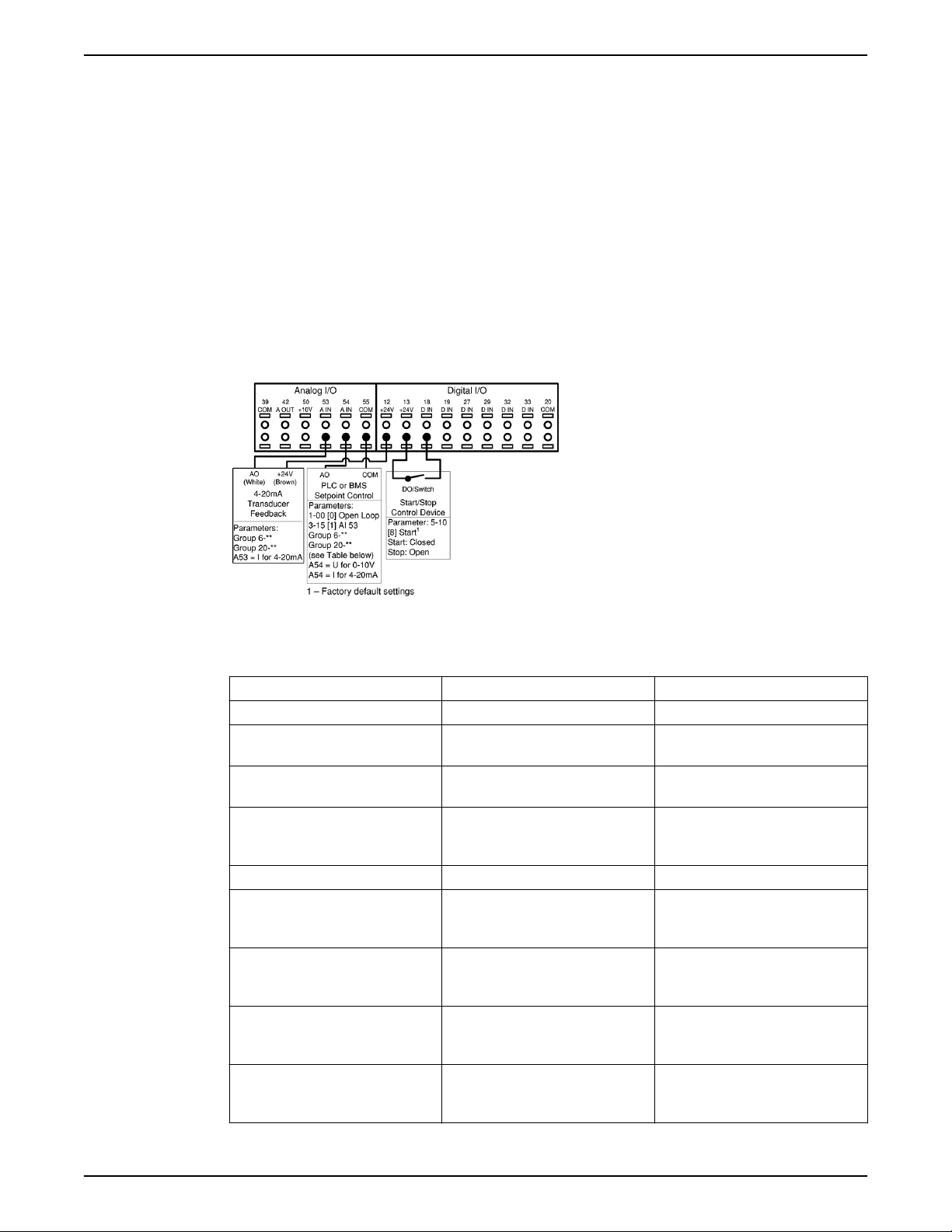
Control from external PLC/BMS through Analog Input
The controller can be configured to accept either the process variable (e.g. actual
pressure) or setpoint from an external control source such as a PLC or BMS controller
through an analog input. The output from the external control device can be either a
voltage or current output signal. Be sure to set the analog input configuration switches
based on the type of output signal. When the process variable is supplied by the external
controller, the wiring connections are the same as used with the connections for speed
control from an external device through an analog input. When the setpoint or reference
is supplied to the controller from the external device both a transducer and the external
control device supplying the setpoint need to be connected to the controller. Refer to the
wiring diagram below. The parameter settings for this configuration are shown below.
Electrical Installation
Figure 25: Connections for setpoint control through an external device
Table 9: Parameters for external PLC/BMS
Parameter Number Parameter Description For setpoint from BMS/PLC
3-15 Reference 1 Source Analog Input 54
6-22* Terminal 54 Low Current Minimum current value for the signal
from the BMS/PLC.
6-23* Terminal 54 High Current Maximum current value for the signal
from the BMS/PLC.
6-25 Terminal 54 High Ref./Feedb. Value Maximum reference/setpoint value.
For example, for a 300psi maximum
setpoint, set to 300.
6-27 Terminal 54 Sensor Fault Enabled
20-00 Feedback 1 Source Select as appropriate for application.
This can be any selection except the
setting of parameter 3-15.
20-12 Reference/Feedback Unit Select as appropriate for application.
For example, set to psi when using
pressure reference.
20-13 Minimum Reference/Feedback Minimum reference/setpoint value.
For example, for a 0-300psi
transducer, set to 0 psi.
20-14 Maximum Reference/Feedback Maximum reference/setpoint value.
For example, for a 300psi transducer,
set to 300 psi.
Aquavar® Intelligent Pump Controller INSTRUCTION MANUAL 39

Electrical Installation
Duplex control wiring
* To use a voltage signal from the PLC/BMS, configure parameters 6-20, 6-21, and set
switch A54 to U.
The controller can be configured to operate in a duplex control system having 2
controllers and 2 variable speed pumps. In this configuration pumps can be staged and
destaged as needed and the lead pump can be alternated. When both pumps are on they
operate at the same frequency. To configure the controller for this type of system, a
specific wiring configuration is required. The diagram below shows the wiring required to
implement the duplex control system.
Figure 26: Duplex wiring
Duplex Control Mode requires a specific set of parameters in order to ensure proper
functionality. The Start-Up Genie must be used to configure the Duplex Control Mode.
See the Commissioning section for details.
Control from external PLC/BMS through communications port
A BMS or PLC can be connected to the control through the communications port. In this
configuration, the BMS or PLC can control the drive by overriding the setpoint, supplying
the process variable or by providing a speed command to the drive. Control cables must
be braided screened/shielded and the screen must be connected by means of a cable
clamp at the controller and at the BMS/PLC. Refer to Using Screened Control Cables for
40 Aquavar® Intelligent Pump Controller INSTRUCTION MANUAL

Electrical Installation
details on installing shielded/screened cables. The parameter list in the table below
shows parameters used to configure communication for two common protocols, Modbus
RTU and BACnet. The parameter list in the second table below shows parameters that
determine the control source for certain drive functions. Use these parameters to
determine whether digital inputs or the BMS/PLC has control of the function.
Figure 27: Connections for external control source connected through comm. port
Table 10: Parameter settings for Modbus RTU and BACnet protocols
Parameter Number Parameter Description Protocol
Modbus RTU BACnet
8-02 Control Source FC Port FC Port
8-30 Protocol Modbus RTU BACnet
8-31 Address 1 1
8-32 Baud Rate 19200 9600
8-33 Parity/Stop bit Even Parity, 1 Stop bit No Parity, 1 Stop bit
8-34 Estimated cycle time 0 ms 0 ms
8-35 Minimum Response Delay 10 ms 10 ms
8-36 Maximum Response Delay 5000 ms 5000 ms
8-37 Maximum Inter-Char Delay 0.86 ms 25 ms
Table 11: Parameters determining control source for controller functions
Parameter number Description Set to
8-01 Control Site Determines the location of the control source.
Set to Digital and ctrl.word to use both serial
bus and digital input control. Set to Digital
only to use only the digital inputs. Set to
Controlword only to use only the serial bus.
8-50 Coasting Select Determines the control location of the coasting
(stop) function. Set to Digital input to use a
digital input only. Set to Bus to use only the
serial bus only. Set to Logic AND to use the
serial bus AND a digital input. Set to Logic OR
to use the serial bus OR a digital input.
Aquavar® Intelligent Pump Controller INSTRUCTION MANUAL 41

Electrical Installation
Parameter number Description Set to
8-53 Start Select Determines the control location of the start
command. Set to Digital input to use a digital
input only. Set to Bus to use only the serial bus
only. Set to Logic AND to use the serial bus
AND a digital input. Set to Logic OR to use the
serial bus OR a digital input.
8-55 Set-up Select* Determines the control location of the set-up
selection function. Set to Digital input to use a
digital input only. Set to Bus to use only the
serial bus only. Set to Logic AND to use the
serial bus AND a digital input. Set to Logic OR
to use the serial bus OR a digital input.
8-56 Preset Reference Select* Determines the control location of the preset
reference selection function. Set to Digital
input to use a digital input only. Set to Bus to
use only the serial bus only. Set to Logic AND
to use the serial bus AND a digital input. Set to
Logic OR to use the serial bus OR a digital
input.
* The Set-up Select and Preset Reference Select functions are used to control other preconfigured functions in the controller. To avoid interfering with these functions, it is
recommended to control this function via digital inputs.
Local control panel
The controller is equipped with a local control panel (LCP). The LCP combines the status
screen and keypad found on the front of the controller. The LCP is the user interface to the
controller. The LCP allows the user to perform various functions such as:
• Start, stop and control speed with the keypad when in local/Hand mode
• View and display the status of the controller, pump and system
• Provides access to all parameters and start up functions
• Manually reset the controller after a fault
• Perform parameter backup
42 Aquavar® Intelligent Pump Controller INSTRUCTION MANUAL

Electrical Installation
Controller status
Figure 28: Default configuration
1. Controller Status
2. Motor HP (Parameter 0-20)
3. Motor Frequency (Parameter 0-21)
4. Motor Current (Parameter 0-22)
5. Feedback/Actual Pressure or process variable (Parameter 0-23)
6. Setpoint (Parameter 0-24)
7. Menu keys
8. Navigation keys
9. Operation keys
10. Status lights
The parameters shown are the factory default settings. To display other values, modify
parameters 0–20, 0–21, 0–22, 0–23, or 0–24.
The controller status line shows operational information about the controller.
The first word in the status line shows the Operation Mode. The table below defines the
Operation Mode status.
Off The controller does not react to any control signal until
[Auto On] is pressed.
Auto On The controller is controlled from the control terminal
and/or the serial communication.
Aquavar® Intelligent Pump Controller INSTRUCTION MANUAL 43

Electrical Installation
Hand On The controller can be controlled by the navigation keys on
the LCP. Stop commands, reset, reversing, DC brake, and
other signals applied to the control terminals can
override local control.
The second word in the status line shows the Reference Site.
Remote The speed reference is given from external signals, serial
communication, or internal preset references.
Local The controller converter uses [Hand On] control or
reference values from the LCP.
The third word in the status line shows the Operation Status.
AC Brake AC Brake was selected in 2–10 Brake Function. The AC
brake over-magnetizes the motor to achieve a controlled
slow down.
AMA finish OK Automatic motor adaptation (AMA) was carried out
successfully.
AMA ready AMA is ready to start. Press [Hand On] to start.
AMA running AMA process is in progress.
Braking The brake chopper is in operation. Generative energy is
absorbed by the brake resistor.
Braking max. The brake chopper is in operation. The power limit for the
brake resistor defined in 2–12 Brake Power Limit (kW) has
been reached.
Coast • Coast inverse was selected as a function for a digital
input (parameter group 5–1* Digital Inputs). The
corresponding terminal is not connected.
• Coast activated by serial communication.
Ctrl. Ramp-down Control Ramp-down was selected in 14–10 Mains Failure.
• The mains voltage is below the value set in 14–11
Mains Voltage at Mains Fault
• The controller ramps down the motor using a
controlled ramp down
Current high The controller output current is above the limit set in 4–
51 Warning Current High.
Current Low The controller output current is below the limit set in 4–
52 Warning Speed Low.
DC Hold DC hold is selected in 1–80 Function at Stop and a stop
command is active. The motor is held by a DC current set
in 2–00 DC Hold/Preheat Current.
DC Stop The motor is held with a DC current (2–01 DC Brake
Current) for a specified time (2–02 DC Braking Time).
• DC Brake is activated in 2–03 DC Brake Cut In Speed
[RPM] and a Stop command is active.
• DC Brake (inverse) is selected as a function for a
digital input (parameter group 5–1* Digital Inputs).
The corresponding terminal is not active.
• The DC Brake is activated via serial communication.
Feedback high The sum of all feedbacks is above the feedback limit set
in 4–57 Warning Feedback High.
Feedback low The sum of all actives is below the feedback limit set in 4–
56 Warning Feedback Low.
44 Aquavar® Intelligent Pump Controller INSTRUCTION MANUAL

Electrical Installation
Freeze output The remote reference is active, which holds the present
speed.
• Freeze output was selected as a function for a digital
input (parameter group 5–1* Digital Inputs). The
corresponding terminal is active. Speed control is
only possible via the terminal functions Speed Up
and Speed Down.
• Hold ramp is activated via serial communication.
Freeze output request A freeze output command has been given, but the motor
will remain stopped until a run permissive signal is
received.
Freeze Reference Freeze Reference was chosen as a function for a digital
input (parameter group 5–1* Digital Inputs). This
corresponding terminal is active. The controller saves the
actual reference. Changing the reference is now only
possible via terminal functions Speed Up and Speed
Down.
Jog request A jog command has been given, but the motor will be
stopped until a run permissive signal is received via a
digital input.
Jogging The motor is running as programmed in 3–19 Jog Speed
[RPM].
• Jog was selected as function for a digital input
(parameter group 5–1* Digital Inputs). The
corresponding terminal (e.g. Terminal 29) is active.
• The Jog Function is activated via the serial
communication.
• The Jog function was selected as a reaction for a
monitoring function (e.g. No signal). The
monitoring function is active.
Motor check In 1–80 Function at Stop, Motor Check was selected. A
stop command is active. To ensure that a motor is
connected to the controller, a permanent test current is
applied to the motor.
OVC control Overvoltage control was activated in 2–17 Overvoltage
Control, [2] Enabled. The connected motor is supplying
the controller with generative energy. The overvoltage
control adjusts the V/Hz ratio to run the motor in
controlled mode and to prevent the controller from
tripping.
PowerUnit Off (For controllers with an external 24 V power supply
installed only.) Mains supply to the controller is removed,
but the control card is supplied by the external 24 V.
Protection md Protection mode is active. The unit has detected a critical
status (an overcurrent or overvoltage).
• To avoid tripping, switching frequency is reduced to
4 kHz.
• If possible, protection mode ends after
approximately 10 s
• Protection mode can be restricted in 14–26 Trip
Delay at Inverter Fault
Aquavar® Intelligent Pump Controller INSTRUCTION MANUAL 45

Electrical Installation
QStop The motor is decelerating using 3–81 Quick Stop Ramp
Time.
• Quick stop inverse was chosen as a function for a
digital input (parameter group 5–1* Digital Inputs).
The corresponding terminal is not active.
• The quick stop function was activated via serial
communication.
Ramping The motor is accelerating/decelerating using the active
Ramp Up/Down. The reference, a limit value or a
standstill is not yet reached.
Ref. high The sum of all active references is above the reference
limit set in 4–55 Warning Reference High.
Ref. low The sum of all active references is below the reference
limit set in 4–54 Warning Reference Low.
Run on ref. The controller is running in the reference range. The
feedback value matches the setpoint value.
Run request A start commend has been given, but the motor is
stopped until a run permissive signal is received via
digital input.
Running The motor is driven by the controller.
Sleep mode The energy saving function is enabled. This means that at
present the motor has stopped, but that it will restart
automatically when required.
Speed high Motor speed is above the value set in 4–53 Waning
Speed High.
Speed low Motor speed below the value set in 4–52 Warning Speed
Low.
Standby In Auto On mode, the controller will start the motor with
a start signal from a digital input or serial
communication.
Start delay In 1–71 Start Delay, a delay starting time was set. A start
command is activated and the motor will start after the
start delay time expires.
Start fwd/rev Start forward and start reverse were selected as functions
for two different digital inputs (parameter group 5–1*
Digital Inputs). The motor will start in forward or reverse
depending on which corresponding terminal is activated.
Stop The controller has received a stop command from the
LCP, digital input or serial communication.
Trip An alarm occurred and the motor is stopped. Once the
cause of the alarm is cleared, the controller can be reset
manually by pressing [Reset] or remotely by control
terminals or serial communication.
Trip lock An alarm occurred and the motor is stopped. Once the
cause of the alarm is cleared, power must be cycled to the
controller. The controller can then be reset manually by
pressing [Reset] or remotely by control terminals or serial
communication.
LCP parameters
The display configuration shown above represents the default settings. Items 2-6 can be
adjusted to display other values. To display other values, modify parameters 0-20, 0-21,
0-22, 0-23 or 0-24 which correspond to 2, 3, 4, 5 and 6 respectively.
46 Aquavar® Intelligent Pump Controller INSTRUCTION MANUAL
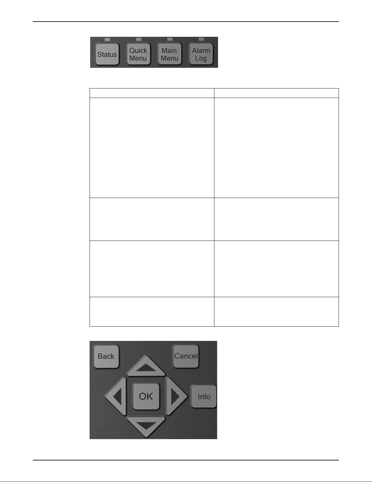
Menu keys
Electrical Installation
Table 12: Function description of menu keys
Key Function
Status Pressing the [Status] key toggles between different status
screens. There are three different status screens; five
readouts (default), four line readouts or Smart Logic
Control.
• Use the [Status] key for selecting the mode of the
LCP or for changing back to Status Display mode
from any other menu.
• The LCP display contrast can also be adjusted by
pressing [Status] plus [▲] or [▼] to adjust the
display brightness..
• The symbol in the upper right corner of the display
shows the direction of motor rotation (arrow), which
set-up is active (number) and which is being
programmed (number in parenthesis).
Quick Menu Pressing the [Quick Menu] key provides access to a set of
submenus that allows easy access to some common
parameters as well as the Start-Up Genie. The Quick
Menu consists of My Personal Menu, Quick Set-up,
Function Set-up, Start-Up Genie, changes made and
Loggings.
Main Menu Pressing the [Main Menu] key allows access to the
complete parameter set. Press [Main Menu] twice to
access the top level index. Press [Main Menu] once to
return to the last location accessed. Press and hold [Main
Menu] for 5 seconds provides access to the Parameter
Shortcut. The Parameter shortcut allows the user to enter
a parameter number to give direct access to that
parameter.
Alarm Log The [Alarm Log] key allows access to the 5 latest alarms
numbers A1–A5. To obtain details about an alarm, use
the arrow keys to highlight the alarm number and press
OK.
Navigation keys
Aquavar® Intelligent Pump Controller INSTRUCTION MANUAL 47
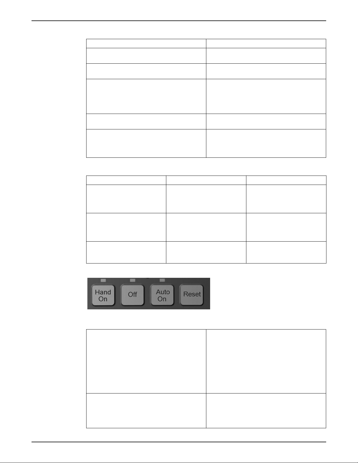
Electrical Installation
Table 13: Navigation keys functions
Key Function
Back Pressing the [Back] key reverts to the previous step or
layer in the navigation structure.
Cancel Pressing the [cancel] button will cancel the last change or
command as long as the display has not been changed.
Info Pressing the [Info] button will display information about
a command, parameter, or function in any display
window. [Info] provides detailed information when
needed. Exit the Info mode by pressing either [Info],
[Back], or [Cancel].
OK [OK] is used for choosing a parameter marked by the
cursor and for enabling the change of a parameter.
Arrows The four navigation arrows are used to navigate between
the different choices available in [Quick Menu], [Main
Menu] and Alarm Log]. Use these keys to move the
cursor.
Table 14: Indicator lights functions
Light Indicator Function
Green ON The ON light activates when the
controller receives power from mains
voltage, a DC bus terminal, or an
external 24 V supply.
Yellow WARN When warning conditions are met,
the yellow WARN light comes on and
text appears in the display area
identifying the problem.
Red ALARM A fault condition causes the red alarm
light to flash and an alarm text is
displayed/
Operation keys
Table 15: Operation keys functions
Hand On The [Hand On] key enables control of the drive via the
LCP interface. Pressing [Hand On] also starts the motor
and the speed can be manually adjusted using the arrow
keys. The [Hand On] key can be enabled or disabled via
parameter 0–40 [Hand On] key on LCP. If [Hand On] is
active the drive can be stopped by:
• Start signal on DI 18
• The [Off] button
• Stop command from serial communication
Off Pressing the [Off] key will stop the motor. The [Off] key
can be enabled or disabled via parameter 0–41 [Off] key
on LCP. If no external stop function is selected and the
[Off] key is disabled, the motor can only be stopped by
disconnecting the mains supply.
48 Aquavar® Intelligent Pump Controller INSTRUCTION MANUAL

Status lights
Electrical Installation
Auto On Pressing the [Auto On] key enables the drive to be
controlled via the control terminals and/or serial
communication. When a start signal is applied on the
control terminals and/or serial communication, the drive
will start. This key can be enabled or disabled via 0–42
[Auto On] key on LCP.
Reset The [Reset] key is used for resetting the controller after an
alarm (trip). The key can be enabled or disabled via
parameter 0–43 [Reset] key on LCP.
Parameter backup
If certain threshold values are exceeded, the alarm and/or Warning (Warn.) LED will turn
on. If an alarm or warning is active, a status or alarm text will appear on the control panel.
• Yellow Warn. LED: Indicates a warning is active.
• Red Flashing Alarm LED: Indicates an alarm is active.
The On LED is activated when the controller receives power.
• Green On LED: Control section is powered and working.
Parameter settings are stored internally in the controller. The parameters can be
uploaded to the LCP for backup or to easily transfer the parameter settings from one
controller to another controller. A factory reset does not change the data stored in the
LCP.
NOTE: Parameter data can be uploaded to the LCP through the use of the Start-Up Genie.
Simply select Copy to LCP from the setup selection menu at the beginning of the Genie.
To upload parameters to the LCP without the use of the Start-Up Genie follow the
following procedure:
1. Press [Off] to stop the motor before uploading data.
2. Press [Main Menu] to enter the parameter list.
3. Select 0-**Operation/Display, press [OK].
4. Use the down arrow to scroll to 0-5* Copy/Save, press [OK] to enter the submenu.
5. Press [OK] to enable editing of parameter 0-50 LCP Copy.
6. Use the up or down arrows to scroll to ALL to Copy, press [OK] to select.
7. The progress bar will show the status of the process.
8. Press [Status] to return to the main status screen.
9. Press [Auto On] or [Hand On] to resume previous operating mode.
NOTE: Parameter data can be uploaded to the LCP through use of the Start-Up Genie.
Simply select Copy from LCP from the setup selection menu at the beginning of the
Genie. Select All to copy all parameters from the LCP including size dependent data.
Select Application Only to copy all size independent data.
To download parameters to the controller from the LCP without use of the Start-Up Genie
follow the procedure below.
Aquavar® Intelligent Pump Controller INSTRUCTION MANUAL 49

Electrical Installation
Factory Reset
1. Press [Off] to stop the motor before uploading data.
2. Press [Main Menu] to enter the parameter list.
3. Select 0-** Operation/Display, press [OK].
4. Use the down arrow to scroll to 0-5* Copy/Save, press [OK] to enter the submenu.
5. Press [OK] to enable editing of parameter 0-50 LCP Copy.
6. To copy all data from the LCP, including size dependent data, use the up or down
arrows to scroll to All from LCP, press [OK] to select. To copy all size independent
data, scroll to Size indep. from LCP, press [OK] to select.
7. The progress bar will show the status of the process.
8. Press [Status] to return to the main status screen.
9. Press [Auto On] or [Hand On] to resume previous operating mode.
A factory reset can be performed to restore the controller back to default settings. There
are multiple ways to perform this function.
Parameter 14-22 Operation Mode can be used to perform the factory reset function.
Using this method does not change controller data such as operating hours, serial
communication selections, fault log, alarm log, and other monitoring functions. To
perform the reset through parameter 14-22 perform the following steps.
1. Press [Main Menu] to enter the parameter list.
2. Use the up and down arrows to scroll to 14-** Special Functions, press [OK].
3. Use the up and down arrows to scroll to 14-2* Reset Functions, press [OK].
4. Use the up and down arrows to scroll to 14-22 Operation Mode, press [OK].
5. Press [OK] to enable modification of the parameter.
6. Use the up and down arrows to scroll to Initialization, press [OK].
7. Remove input power from the unit and wait for the LCP to turn off.
8. Apply power to the unit. The reset is performed at power up.
9. Alarm 80 Drive Initialized to Default Value will be displayed.
10. Press [Reset] to return to operation mode.
Another way to perform the factory reset is to issue a 3 finger reset. The process is
described below.
1. Remove power from the unit and wait for the LCP to turn off.
2. Press and hold [Status], [Main Menu], and [OK] at the same time. While holding down
the buttons, apply power to the unit.
50 Aquavar® Intelligent Pump Controller INSTRUCTION MANUAL

Mechanical Installation
a
b
Installation requirements
Cooling
• To provide cooling airflow, mount the unit to a solid flat surface or to the optional
back plate.
• Top and bottom clearance for air cooling must be provided. Generally, 100–225 mm
(4–10 in) is required.
Mechanical Installation
Lifting
Mounting
Enclosure A2–A5 B1–B4 C1, C3 C2, C4
a/b 100 mm (3.9 in) 200 mm (7.9 in) 200 mm (7.9 in) 225 mm (8.9 in)
• Improper mounting can result in overheating and reduced performance.
• Derating for temperatures starting between 40°C (104°F) and 50°C (122°F) and
elevation 1000 m (3300 ft) above sea level must be considered. See the Technical
Bulletin for detailed information.
• Check the weight of the unit to determine a safe lifting method.
• Ensure that the lifting device is suitable for the task.
• If necessary, plan for a hoist, crane, or forklift with the appropriate rating to move the
unit.
• For lifting, use hoist rings on the unit, when provided.
• Mount the unit vertically.
• The frequency converter allows side by side installation.
• Ensure that the strength of the mounting location will support the unit weight.
• Mount the unit to a solid flat surface or to the optional back plate to provide cooling
airflow.
Aquavar® Intelligent Pump Controller INSTRUCTION MANUAL 51
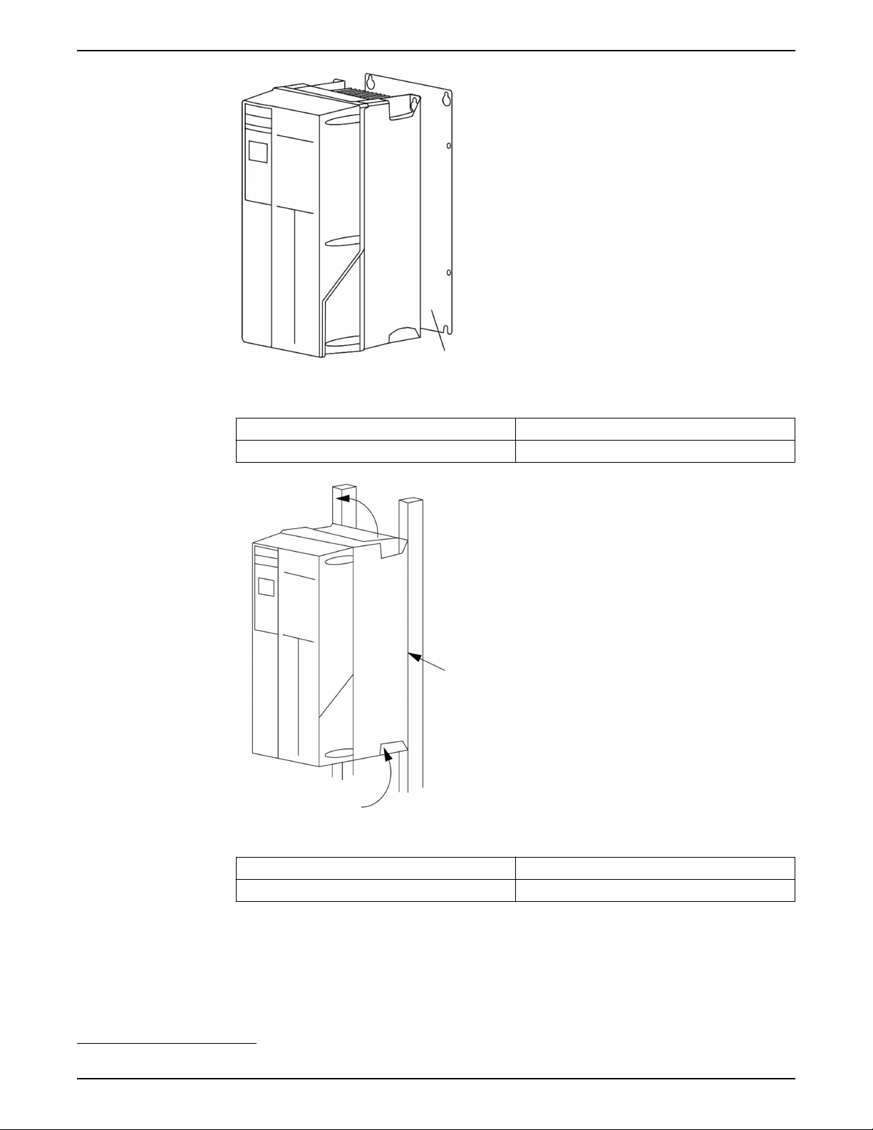
A
1
Mechanical Installation
Figure 29: Mounting with back plate
Item Description
A Properly installed back plate
Figure 30: Mounting with railings
Item Description
1 Back plate
1
Tightening torques
See Technical Specification section for details.
1
Back plate is needed when mounted on railings.
52 Aquavar® Intelligent Pump Controller INSTRUCTION MANUAL

Piping connections
Mechanical Installation
NOTICE:
All plumbing work must be performed by a qualified technician. Always follow all local,
state and provincial codes.
A proper installation requires a pressure relief valve, a diaphragm tank, a 1/4” female NPT
threaded fitting for the pressure sensor, and properly sized pipe. Piping should be no
smaller than pump discharge and/or suction connections. Piping should be kept as short
as possible. Avoid the use of unnecessary fittings to minimize friction losses.
CAUTION:
Use pipes suited to the maximum working pressure of the pump. Failure to do so can
cause the system to rupture, with the risk of injury.
All joints must be airtight. Use
Teflon tape or another type of pressure sealant to seal
threaded connections. Please be careful when using thread sealant as any excess that
gets inside the pipe may plug the pressure sensor.
Galvanized fittings or pipe should never be connected directly to the stainless steel
discharge head or casing as galvanic corrosion may occur. Barb type connectors should
always be double clamped.
WARNING:
Do not install any valves (except check valves), flow control devices or filters between the
pressure transducer and the pump. It is allowable to run branches off the pipe between
the pump and transducer as long as no flow restricting devices are between the pump
and transducer.
Diaphragm tank, pressure relief valve and discharge piping
Use only “pre-charged” tanks on this system. Do not use galvanized tanks. Select an area
that is always above 34°F (1.1°) in which to install the tank, pressure sensor and pressure
relief valve. If this is an area where a water leak or pressure relief valve blow-off may
damage property, connect a drain line to the pressure relief valve. Run the drain line fro
the pressure relief valve to a suitable drain or to an area where water will not damage
property.
Diaphragm tank, system pressure
A diaphragm tank (not included) is used to cushion the pressure system during start-up
and shut-down. It should be sized to at least 20% of the total capacity of your pump. For
example: If your pump is sized for 100 GPM then size your tank for at least 20 gallon total
volume, not draw down. Pre-charge your bladder tank to 15–20 PSI below your system
pressure. The controller is pre-set for 50 PSI at the factory. Therefore a 30–35 PSI precharge in your tank would be required. Use the higher tank pre-charge setting if the
system drifts over 5 PSI at a constant flow rate. NOTE: Pre-charge your tank before filling
with water.
The maximum working pressure of the HydroPro diaphragm tank is 125 PSI.
CAUTION:
Exceeding the working pressure of the tank can cause the tank to rupture or explode.
Installing the pressure sensor
The pressure sensor requires a 1/4” FNPT fitting for installation. Install the pressure sensor
with the electrical connector pointing up to avoid clogging the pressure port with debris.
Install the pressure sensor in a straight run of pipe away from elbows or turbulence. For
optimum pressure control install the pressure sensor in the same straight run of pipe as
Aquavar® Intelligent Pump Controller INSTRUCTION MANUAL 53

Mechanical Installation
the pressure tank. Ensure the pressure sensor is within 10 feet of the pressure tank.
Installing the pressure sensor far away from the pressure tank may result in pressure
oscillations. Do not install the pressure sensor in a location where freezing can occur. A
frozen pipe can cause damage to the pressure sensor.
Underwater connection
When using submersible motors, a waterproof connection is required between the drop
cable and motor leads. The underwater connection where the drop cable connects to the
motor wires must be made using a waterproof heat shrink kit. To make the connection:
1. Strip the wires 1/2” and place the heat shrink tubes over the wires.
2. Connect the wires using the crimps.
3. Shrink the tubes over the crimps by heating from the center outward.
Vinyl electrical tape is not acceptable for underwater splices when using variable speed
drives. There is a high potential for leakage to ground through taped joints.
CAUTION:
Failure to use a waterproof heat shrink kit will void the warranty.
• The sealant in the tube will flow over the ends making a watertight seal.
• If a heat shrink tube is burnt or split, the connection will need to be remade.
Before installing the motor in the well, the drop cable must be connected to the motor
wires. Refer to the wire size chart when selecting wire size for the drop cable.
54 Aquavar® Intelligent Pump Controller INSTRUCTION MANUAL

Operation
Pre-start procedure
Electrical Hazard:
If input and output connections have been connected improperly, there is potential for
high voltage on these terminals. If power leads for multiple motors are improperly run in
same conduit, there is potential for leakage current to charge capacitors within the
frequency converter, even when disconnected from mains input. For initial start up, make
no assumptions about power components. Follow pre-start procedures. Failure to follow
pre-start procedures could result in personal injury or damage to equipment.
1. Make sure input power to unit is OFF and locked out. Do not rely on the frequency
converter disconnect switches for input power isolation.
2. Verify that there is no voltage on input terminals L1 (91), L2 (92), and L3 (93), phase-to-
phase and phase-to-ground.
3. Verify that there is no voltage on output terminals 96 (U), 97 (V), and 98 (W), phase-to-
phase and phase-to-ground.
4. Confirm continuity of the motor by measuring ohm values on U-V (96-97), V-W
(97-98), and W-U (98-96).
5. Check for proper grounding of the frequency converter as well as the motor.
6. Inspect the frequency converter for loose connections on terminals.
7. Record the following motor-nameplate data: power, voltage, frequency, full load
current, and nominal speed. These values are needed to program motor nameplate
data later.
8. Confirm that the supply voltage matches voltage of frequency converter and motor.
Operation
Pre-startup inspections
Item to Inspect Description Checked
Auxiliary equipment • Look for auxiliary equipment, switches, disconnects, or input fuses/circuit breakers that may
reside on input power side of the frequency converter or output side to motor. Ensure they
are ready for full speed operation.
• Check function and installation of any sensors used for feedback to the frequency converter.
• Remove power factor correction caps on motor(s), if present.
Cable routing • Ensure that input power, motor wiring and control wiring are separated or in three separate
metallic conduits for high frequency noise isolation.
Control wiring • Check for broken or damaged wires and connections.
• Check that control wiring is isolated from power and motor wiring for noise immunity.
• Check the voltage source of the signals, if necessary.
• The use of shielded cable or twisted pair is recommended. Ensure that the shield is
terminated correctly.
Cooling clearance • Measure that top and bottom clearance is adequate to ensure proper air flow for cooling.
EMC considerations • Check for proper installation with regard to electromagnetic capability.
Environmental conditions • See equipment tech label for the maximum ambient operation temperature limits.
• Humidity levels must be 5–95% non-condensing.
Fusing and circuit breakers • Check for proper fusing or circuit breakers.
• Check that all fuses are inserted firmly and in operational condition and that all circuit
breakers are in the open position.
Aquavar® Intelligent Pump Controller INSTRUCTION MANUAL 55

Operation
Item to Inspect Description Checked
Grounding (earthing) • The unit requires an earth wire (ground wire) from its chassis to the building ground
(earth) .
• Check for good earth connections (ground connections) that are tight and free of oxidation.
• grounding (earthing) to conduit or mounting the back panel to a metal surface is not a
suitable ground (earth) .
Input and output power
wiring
Panel interior • Inspect that the unit interior is free of dirt, metal chips, moisture, and corrosion.
Switches • Ensure that all switch and disconnect settings are in the proper positions.
Vibration • Check that the unit is mounted solidly or that shock mounts are used, as necessary.
• Check for loose connections.
• Check that motor and mains are in separate conduit or separated screened cables.
• Check for an unusual amount of vibration.
Checked by:
Date:
Apply power
NOTICE:
• HIGH VOLTAGE. Frequency converters contain high voltage when connected to AC
mains. Installation, start-up and maintenance should be performed by
personnel only. Failure to comply could result in death or serious injury.
• UNINTENDED START. When the frequency converter is connected to AC mains, the
motor may start at any time. The frequency converter, motor, and any driven
equipment must be in operational readiness. Failure to comply could result in death,
serious injury, equipment, or property damage.
• POTENTIAL HAZARD IN THE EVENT OF INTERNAL FAILURE! Risk of personal injury
when the frequency converter is not properly closed. Before applying power, ensure
all safety covers are in place and securely fastened.
qualified
1. Confirm that the input voltage is balanced with 3%. If not, correct voltage imbalance
2. Ensure that optional equipment wiring, if present, matches the installation application.
3. Ensure that all operator and start enable devices are in the OFF position. Panel doors
4. Apply power to the unit. DO NOT start the frequency converter at this time. For units
Discharge time
WARNING:
Disconnect and lock out electrical power and wait for the minimum waiting time specified
below. Failure to wait the specified time after power has been removed before
performing service or repair could result in death or serious injury.
Frequency converters contain DC-link capacitors that can remain charged even when the
frequency converter is not powered. To avoid electrical hazards, disconnect:
before proceeding. Repeat this procedure after the voltage correction.
should be closed or cover mounted.
with a disconnect switch, turn to the ON position to apply power to the frequency
converter.
• AC mains
• Any permanent magnet type motors
• Any remote DC-link power supplies, including battery backups, ups and DC-link
connections to other frequency converters.
56 Aquavar® Intelligent Pump Controller INSTRUCTION MANUAL
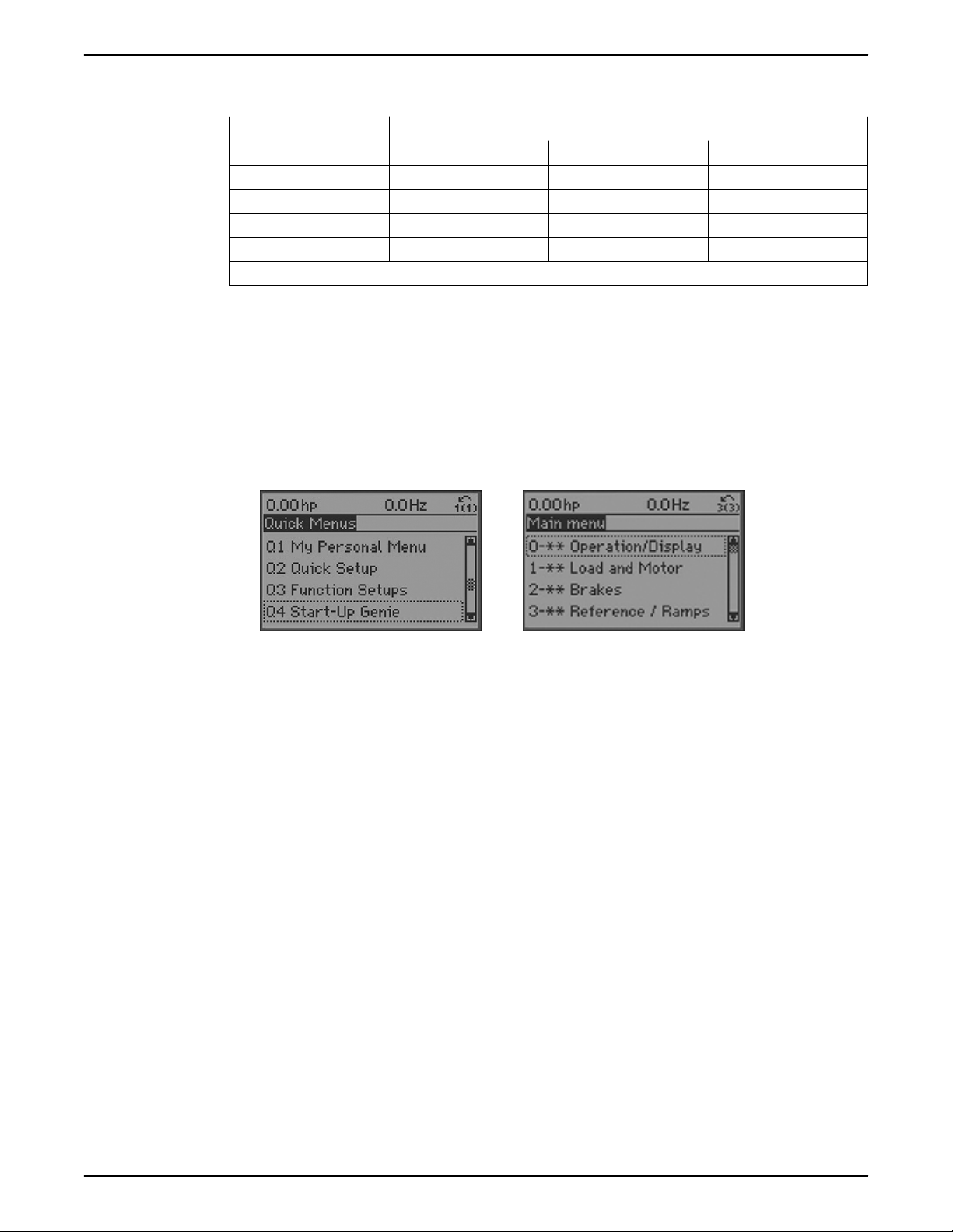
Wait for the capacitors to discharge completely before performing any service or repair
work. Refer to the following table for wait times:
Voltage [V] Minimum waiting time [minutes]
4 7 15
200–240 1.1–3.7 kW 5.5–45 kW
380–480 1.1–7.5 kW 11–90 kW
525–600 1.1–7.5 kW 11–90 kW
525–690 1.1–7.5 kW 11–90 kW
High voltage may be present even when the warning LED indicator lights are off.
Frequency converter programming
Programming the controller
The controller can be programmed by using either the Start-Up Genie, Quick Menus
mode or the Main Menu mode. The Main Menu mode allows access to all parameters. To
modify a parameter or make a selection in either the Start-Up Genie, Quick Menu mode or
the Main Menu mode follow the procedure below:
• To enter the Quick Menu mode press [Quick Menu] or to enter the Main Menu press
[Main Menu].
Operation
• The Start-Up Genie will begin automatically after the 1st power up or it can be rerun
by selecting Start-Up Genie under Quick Menus.
• Select the desired selection in the Start-Up Genie, sub-menu in Quick Menus or
parameter group in Main Menu by using the up and down arrows.
• Press [OK] to enter the sub-menu or selected parameter group.
• Once in the sub-menu or parameter group, use the up and down arrows to highlight
the desired parameter. Press [OK] to select the parameter and enable editing.
• To edit the parameter use the up and down arrows to scroll through the parameter
settings or selections. For numeric values with more than one digit, use the left and
right keys to select the position within the number. The highlighted area can be
modified by using the up and down arrows.
• Press [OK] to accept and save or [Cancel] to disregard the change.
Array parameters allow the
address. An example of an array parameter is 5-40 Function Relay. This parameter allows
configuration of the 2 programmable relays included with the controller. To modify an
array parameter follow the procedure below:
• Enter the Main Menu as previously described.
• Use the up and down arrows to scroll to 5-** Digital In/Out. Press [OK] to enter the
parameter group.
• Use the up and down arrows to scroll to 5-4* Relays. Press [OK] to enter the parameter
sub-group. The screen is shown below.
modification of a group of parameters through one parameter
Aquavar® Intelligent Pump Controller INSTRUCTION MANUAL 57

Operation
Quick menu
• To edit Relay 1, use the up and down arrows to
highlight Relay 1 and press [OK] to select Relay
1.
• Press [OK] again to enable editing of Relay 1.
• Use the up and down arrows to select the
desired relay function.
• Press [OK] to save the selection.
• Use the up and down arrows to select the 5-41
On Delay, Relay or 5-42 Off Delay, Relay. Repeat
the steps above to edit these parameters.
• Press [BACK] to return to the Relays screen and
repeat the above steps to edit the function for
Relay 2.
• Press [Main Menu] to return to the Main Menu.
The Quick Menu mode contains various sub-menus that allow quick and easy access to
common parameters. There are 6 sub-menus under Quick Menus. The 6 sub-menus are
shown in the table below.
My personal menu
Table 16: Quick Menus
Sub-menu Sub-menu Group Name Description
Q1 My Personal Menu Contains parameters commonly used
to configure pump applications.
Q2 Quick Setup Contains parameters commonly used
to configure the controller.
Q3 Function Setups Provides quick access to parameters
commonly required for HVAC
applications.
Q4 Start-Up Genie Guides the user to configure the
controller for various applications.
Q5 Changes Made Shows the last 10 changed
parameters, changes since factory
defaults and input assignments.
Q6 Loggings Displays graph line readouts of the
LCP parameters. To change displayed
LCP parameters use parameters 0–20
to 0–24.
My Personal Menu (Q1) has been configured at the factory to contain 20 parameters
commonly used in pumping applications. Use My Personal Menu to change parameters
while the system is running, such as changing Setpoint. The parameters found in My
Personal Menu are shown below.
58 Aquavar® Intelligent Pump Controller INSTRUCTION MANUAL

Operation
Parameter number Parameter Name Default Value Parameter Description
20-21 Setpoint 50.0 Process setpoint. The
controller will adjust speed
to maintain this value. If
multiple setpoints are
enabled, this parameter will
display and allow
adjustment of the active
setpoint.
22-44 Restart Difference (%) 10% This is the difference
between the setpoint and
feedback that will cause the
controller to restart from
sleep mode. This is entered
as a % of the setpoint. For a
50psi setpoint, a 10%
Restart Difference will cause
the controller to restart from
sleep at 45psi.
4–12 Sleep Frequency/Low
Limit[Hz]
30 Hz This is the minimum speed
of the motor and the speed
at which the controller will
enter sleep mode.
5-11 Terminal 19 Digital Input No operation This general purpose digital
input is designated for the
Pump Protect Function.
5-12 Terminal 27 Digital Input No operation This general purpose digital
input is designated for the
Pump Protect Function.
22-00 Pump Protect Delay 10 s This is the time delay
between detection of a
Pump Protect condition and
the triggering of the Pump
Protect Alarm.
22-26 No Water/Loss of Prime
Function
Man. Reset Alarm This configures the No
Water/Loss of Prime
Function. Set this value to
Man. Reset Alarm in order
to utilize the No Water/Loss
of Prime Restart Function.
22-39 No Water/Loss of Prime
Limit
Size Dependent (HP) This value sets the No
Water/Loss of Prime limit.
When the pump HP falls
below this value while
operating at maximum
speed, the No Water/Loss of
Prime Function will be
implemented after the time
specified in No Water/Loss
of Prime Protection Delay
[22-27].
Aquavar® Intelligent Pump Controller INSTRUCTION MANUAL 59

Operation
Parameter number Parameter Name Default Value Parameter Description
22-50 Under Pressure Function Off This parameter configures
the Under Pressure
Function. The Under
Pressure Alarm/Warning is
issued when the system
pressure falls below the
Under Pressure Limit
[22-52] for longer than the
Under Pressure Time Delay
[22-51].
22-51 Under Pressure Delay Time 30 s This parameter specifies the
time between detection of
an Under Pressure event
and when the action
defined in Under Pressure
Function is issued.
22-52 Under Pressure Difference 10% Under Pressure Difference
is the difference between
the setpoint and the actual
pressure that will trigger
the Under Pressure
Function. This value is set as
a % of Maximum
Reference/Feedb. [20-14]
5-40 Function Relay Relay 1: No Alarm
Relay 2: Running
This parameter configures
Relay 1 and 2 functions.
This array parameter allows
configuration of both relays.
See Programming the
controller for details on how
to navigate the array
parameter screen . [0] =
Relay 1, [1] = Relay 2
5-41 On Delay, Relay Relay 1: 0.01s
Relay 2: 0.01s
This parameter configures
Relay 1 and 2 On Delay
Time. This array parameter
allows configuration of both
relays. See Programming
the controller for details on
how to navigate the array
parameter screen . [0] =
Relay 1, [1] = Relay 2
20-00 Feedback 1 Source Analog Input 53 Feedback source for the PID
controller, transducer input
source.
20-13 Min Reference/Feedb. 0.0 Minimum feedback value
for the transducer.
20-14 Max Reference/Feedb. 300.0 Maximum feedback value
for the transducer.
3-41 Ramp 1 Ramp Up Time 10 s Ramp up time (0 to full
speed). Increasing this time
will produce a slower ramp
up.
3-42 Ramp 1 Ramp Down Time 5 s Ramp down time (full
speed to 0). Increasing this
time will produce a slower
ramp down.
60 Aquavar® Intelligent Pump Controller INSTRUCTION MANUAL

Start-Up Genie
Operation
Parameter number Parameter Name Default Value Parameter Description
20-93 PID Prop Gain 5 Proportional correction gain
for PID controller.
Increasing this value will
produce a faster system
response. CAUTION:
Increasing this value too
high can make the system
unstable and produce
severe oscillations.
20-94 PID Integration Time 3.3 s Integration time for the PID
controller. Increasing this
value will produce a slower
system response. CAUTION:
Decreasing this value too
low can make the system
unstable and produce
severe oscillations.
This controller is equipped with a Start-Up Genie which allows the user to easily configure
the controller for various pump control applications. The Genie configures parameters
that are based on the selections that are made by the user. The Genie allows the user to
configure the motor, application type, inputs, outputs, pump protection features, flow
compensation, and communications. The application types include single pump, constant
slave, duplex control, speed control, and test run mode. See the Setup and
Commissioning section for details.
Main menu
The parameters in the Main Menu are grouped by category. Note that some groups are
not visible unless the appropriate option card is installed. The parameter groups in the
Main Menu are shown below.
Parameter Group Parameter Group Name
0 Operation/Display
1 Load and Motor
2 Brakes
3 Reference/Ramps
4 Limits/Warnings
5 Digital In/Out
6 Analog In/Out
8 Comm. and Options
9 Profibus*
10 CAN Fieldbus*
11 LonWorks*
13 Smart Logic
14 Special Functions
15 Drive Information
16 Data Readouts
18 Info & Readouts
20 Drive Closed Loop
21 Ext. Closed Loop
22 Appl. Functions
Aquavar® Intelligent Pump Controller INSTRUCTION MANUAL 61

Operation
Parameter Group Parameter Group Name
23 Time-based Functions
24 Appl. Functions 2
25 Cascade Controller
26 Analog I/O Option
* Appropriate option card must be installed.
Refer to the appendix for a complete parameter list.
Setup and commissioning
Start-Up Genie
CAUTION:
When a Start (Closed) signal is present on DI18, the controller can start the pump/motor
at any time without warning. Set DI18 to Stop (Open) or press the [Off] operation key
before using the Genie. Apply the Start signal to the controller only when pump/motor
operation is desired.
The Start-Up Genie provides a fast and easy method for
various pump applications. The Navigation keys are used to make selections within the
Genie. The [Info] button can be pressed at any time while in the Genie to retrieve
additional information about the current screen or parameter.
To navigate through the Start-Up Genie, press [OK] to enable editing of a screen or
parameter. Use the up and down arrows to highlight the desired selection then press [OK]
to confirm the selection. Next use the down arrow to save the parameter and navigate to
the next screen. The up arrow transitions to the previous screen. If the screen shows the
desired setting is already selected for a particular parameter or function, simply use the
down arrow to proceed to the next screen.
NOTE: Be sure to press the down arrow to save the parameter after confirming the
selection. This ensures all associated parameter settings and background calculations are
performed and saved properly. After pressing the down arrow to save the parameter the
Genie may be slow to respond as these settings and calculations are performed.
Press [Cancel] to exit parameter editing without saving or to change a saved parameter or
selection back to the previously saved while still in the current screen. Pressing [Back] will
also exit parameter editing without saving. To exit the Start-Up Genie at any time, first exit
parameter editing then press [Back] then [OK].
The arrows shown in the lower right hand corner of the LCP indicate the options for
navigation. When an up arrow is displayed, pressing the up arrow will transition to the
previous screen. When a down arrow is displayed, pressing the down arrow will transition
to the next screen. When both an up and down arrow are displayed then pressing the up
arrow will transition to the previous screen and pressing the down arrow will transition to
the next screen.
NOTE: Ensure the controller is set to Stop (DI 18 Open) and is set to Setup 1 prior to
running the Start-Up Genie. To place the controller in Setup 1, ensure DI 33 is Open and
the controller is set to Lead for Duplex systems. To manually change the lead pump in a
Duplex System press [OK] and the right arrow keys on the lead drive. In Duplex Systems
ensure alternation does not occur while running the Start-Up Genie by pressing [Off]
before entering the Start-Up Genie.
The Genie starts automatically the first time the controller has been powered in the field
or if the Genie has not been used previously. The Genie can be started at any time by
accessing the Quick Menus screen by pressing [Quick Menu] then using the up and down
arrows to highlight Q4 Start-Up Genie. Press [OK] to enter the Genie.
configuring the controller for
62 Aquavar® Intelligent Pump Controller INSTRUCTION MANUAL
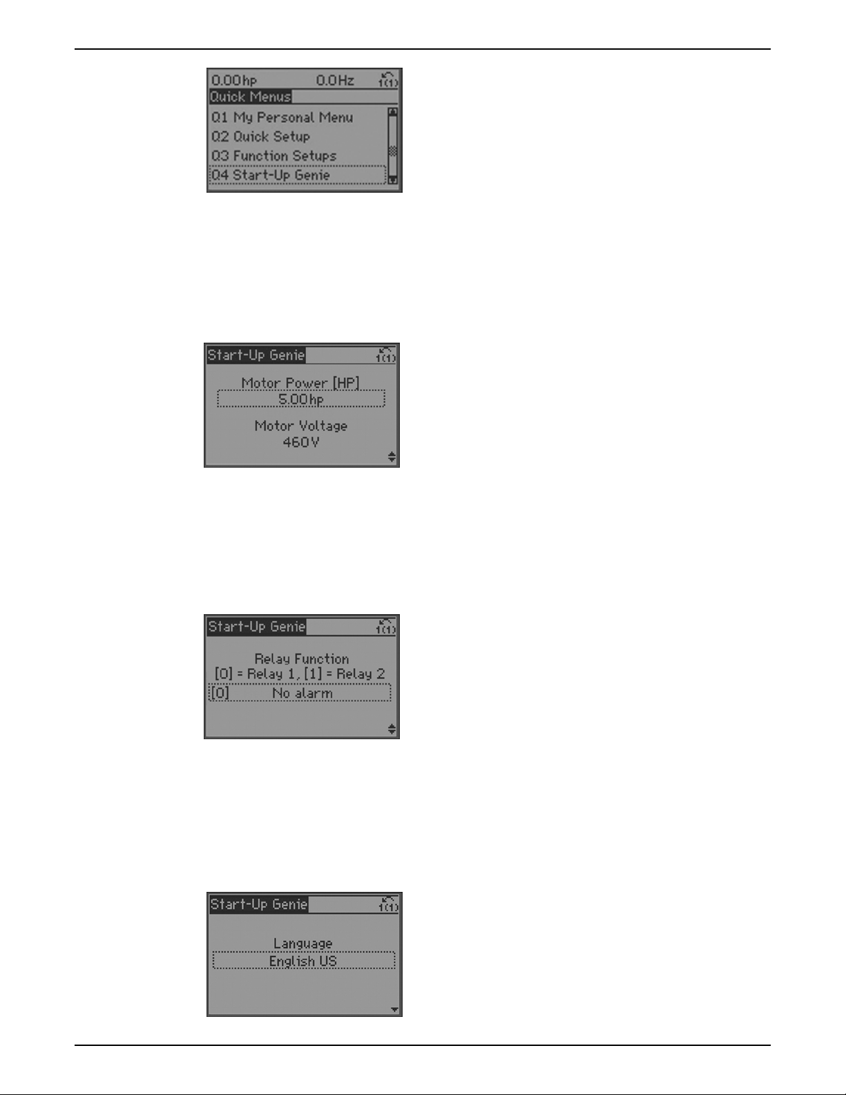
Operation
There are various screen types in the Start-Up Genie. One of these is the dual parameter
screen.
To navigate the dual parameter screen use the up and down arrows to highlight the
desired parameter. Press [OK] to enable editing of the highlighted parameter. Use the up
and down arrows to set the parameter to the desired setting. Press [OK] to confirm the
selection. To modify the other parameter shown, use the up and down arrows to highlight
the other parameter and repeat the steps used to set and confirm the setting the previous
parameter.
The array parameter screen allows configuration of a group of parameters configured as
an array. For example the Relay Function screen shown below is an array parameter
screen.
To navigate the array parameter screen press [OK] to enable editing of the array index.
The array index is shown on the left side of the parameter value. Use the up and down
arrows to select the desired index. Press [OK] to set the array index and enable editing of
the parameter at the selected index. Use the up and down arrows to set the parameter to
the desired setting. Press [OK] to confirm the selection.
Within the Start-Up Genie some screens will display “[unit]” after a parameter value. This
nomenclature is used when a parameter is entered in the control units selected in the
Start-Up Genie. For example, when entering the Setpoint for closed loop pressure control,
the value could be entered in psi, bar, in HG, etc. In this case “[unit]” is used to account for
this variation in units.
The first menu requires the user to set the language. To select a language, press [OK] to
enable parameter editing. Use the up and down arrows to highlight the language then
press [OK] to save the selection.
Aquavar® Intelligent Pump Controller INSTRUCTION MANUAL 63

Operation
Next use the down arrow to proceed to the next section.
If this is the first time the Genie has run, the Genie will guide the user through the setup of
the motor parameters. If the Genie has run previously, the user can choose the desired
Setup Selection to configure a specific function in the controller. Use the up and down
arrows to highlight the desired setup and press [OK] to enter the setup. The choices for
the Setup Selection menu are described in the table below.
Table 17: Setups with the Genie
Setup Description
Motor This setup allows configuration of the motor parameters.
These settings are found on the motor nameplate.
Application The Application setup allows the user to configure the
motor type, operating mode, units and ramps.
Feedback This setup allows configuration of up to 3 feedback
sources. The feedbacks can be taken in to the controller
through analog inputs or communications.
Setpoint This setup allows configuration of up to 2 setpoints. If
multiple setpoints are used, the setpoint is selected by
using DI 33.
Constant Slave This setup configures the controller to operate up to 2
external fixed speed pumps using the 2 on board relays.
Flow Compensation This setup configures the Flow Compensation function
which can automatically adjust the system setpoint to
offset the affect of friction loss in the system.
Pump Protection This setup configures Sleep Mode, Flow Check, No Water/
Loss of Prime and Pump Protect functions.
Digital Input This setup allows configuration of the digital inputs.
Relay and Analog Output This setup allows configuration of the relay and analog
outputs.
Communication This setup configures the on board fieldbus
communications.
Copy to LCP This setup allows all the controller parameters to be
copied to the LCP. This is helpful for saving the drive state
or to quickly configure another controller with the same
settings.
Copy from LCP This setup allows all the controller parameters to be
copied from the LCP. This is helpful for reverting the drive
to a previous state or to quickly configure another
controller with the same settings.
Motor setup
The motor data required to complete the Motor Setup can be found on the motor
nameplate. The Start-Up Genie will prompt the user for Motor Power (HP), Motor Nominal
Voltage, Motor Nominal Frequency (Hz), Motor Nominal Speed (RPM), Motor Current
(FLA), Motor Service Factor (%) and Motor Type. If the Motor Service Factor indicated on
the motor nameplate is 1.15 enter 115% for Motor Service Factor. Be sure to properly set
64 Aquavar® Intelligent Pump Controller INSTRUCTION MANUAL
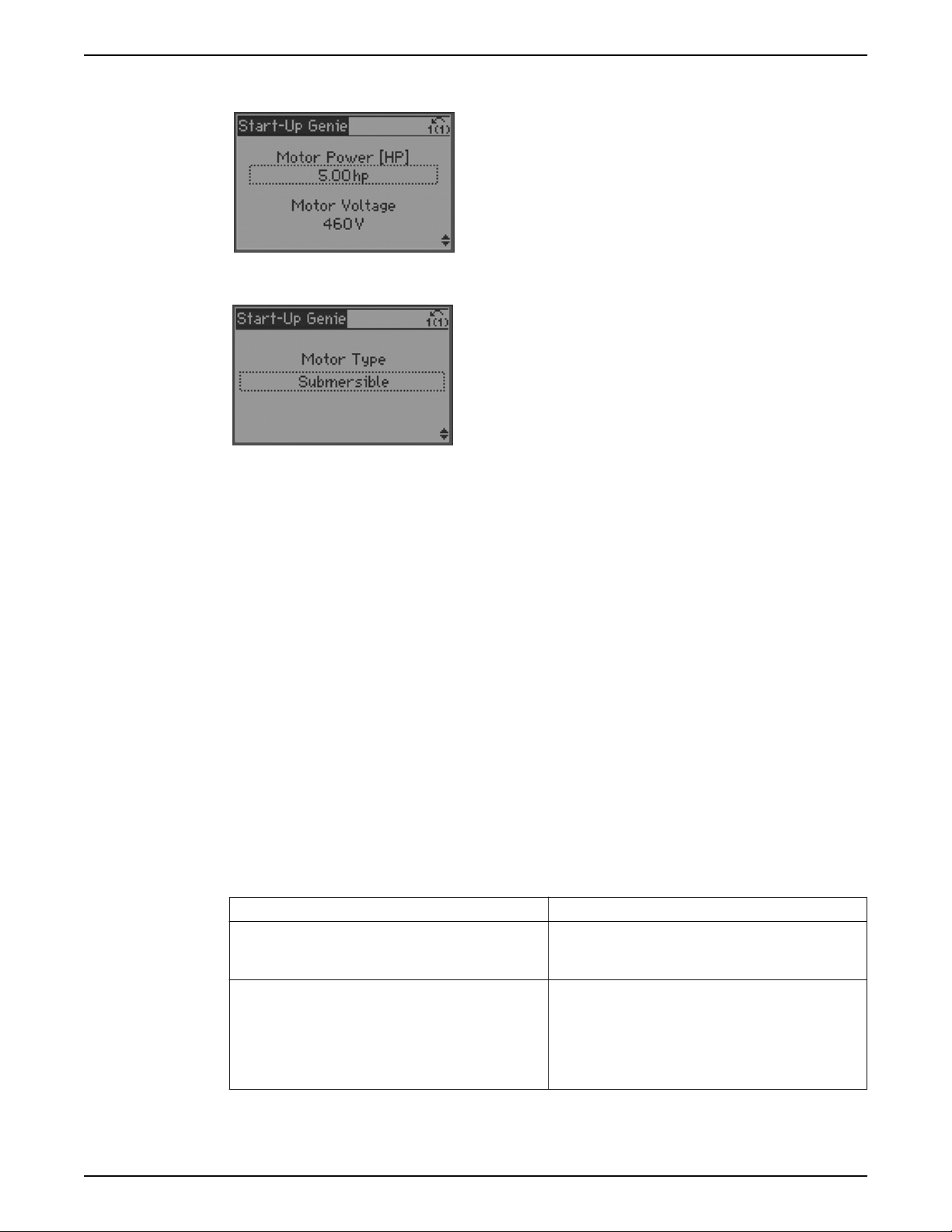
Operation
the motor nominal current and service factor. These parameters will configure the motor
overload protection feature.
The Motor Type menu allows selection of either a Submersible or Surface motor. This
selection will configure specific settings to properly operate the chosen motor type.
• If a Submersible motor is selected, the controller is configured to have a 30Hz
minimum speed (parameter Sleep Frequency/Low Limit [4-12] = 30Hz), ramp from
stop to 30Hz in 1 second (parameters 1-78 = 29Hz and 3-82 = 1 s) and to coast to stop
(parameters 1-80 = Coast, 1-82 = 10Hz).
• If a Surface motor is selected, set the minimum speed (default parameter Sleep
Frequency/Low Limit [4-12] = 30Hz), the stop ramp will be controlled by the default
deceleration ramps (parameters 3-42 and 3-52) and to coast to stop (parameters 1-80
= Coast, 1-82 = 10Hz).
NOTE: There are various parameters that are linked to the motor parameter settings.
Changing the motor parameter settings will also change the settings of these linked
parameters. It is recommended to set the motor parameters first to avoid overwriting any
settings made in the Start-Up Genie.
Application setup
The next menu set is the Application Setup which will allow selection and configuration of
the application type and control response. Select the application type by first selecting the
Operating Mode. Selecting the Operating Mode will configure specific parameters to
configure the selected mode. If the Operating Mode is changed, any changes made to
configure the previously configured Operating Mode will be overwritten. The Operating
Mode can be set to Single Pump, Constant Slave, Duplex Control, Speed Control or Test
Run Mode. The various Operating Modes are defined below.
Table 18: Operating modes
Operating Mode Description
Single Pump This mode is the default Operating Mode. Use this mode
for constant pressure, flow or level applications that use 1
controller operating a single pump.
Constant Slave This mode allows control of up to 2 external fixed speed
pumps using the 2 on board relays. This mode can be
used to extend the capacity of a system by staging fixed
speed pumps as the demand in the system increases.
Pumps can then be destaged as the system demand
decreases.
Aquavar® Intelligent Pump Controller INSTRUCTION MANUAL 65
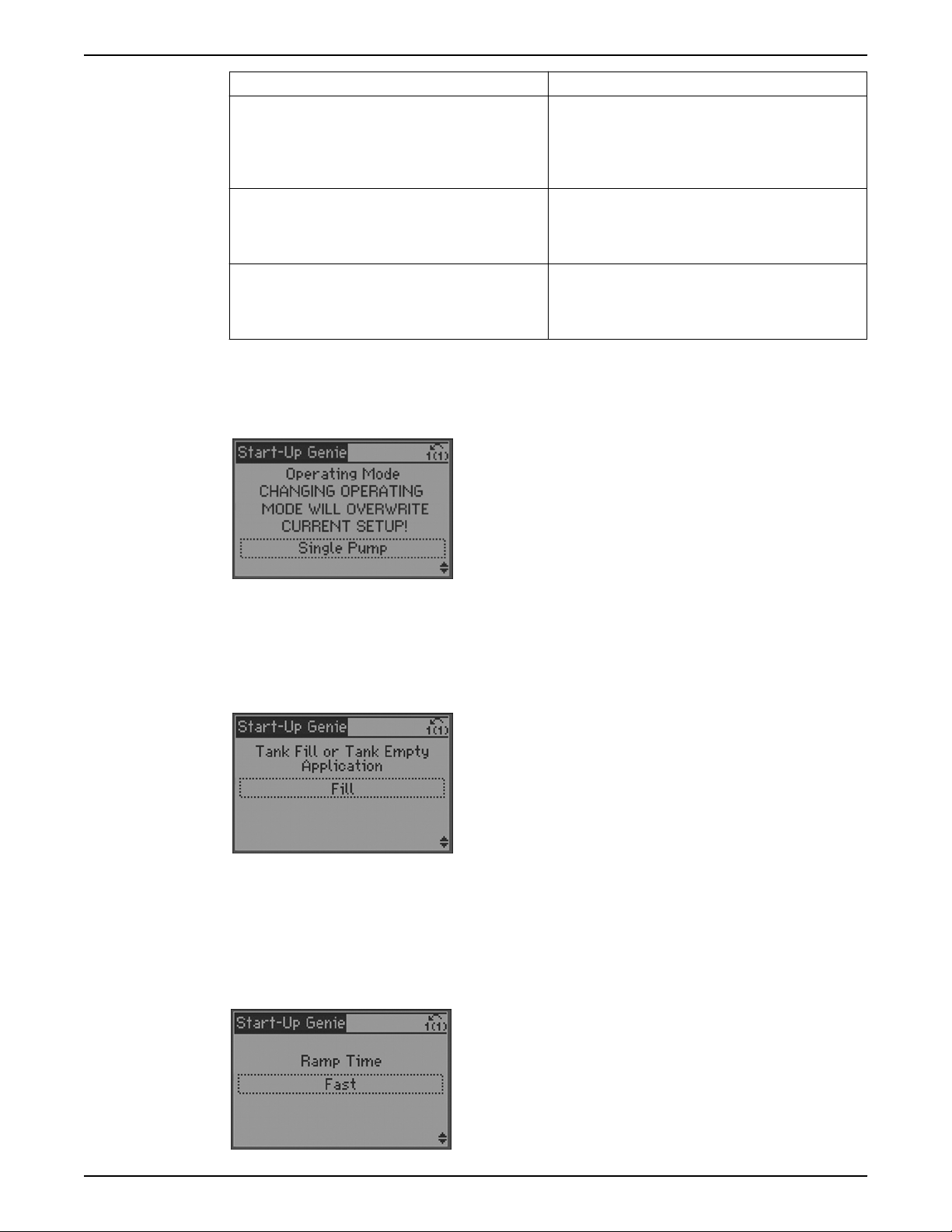
Operation
Single pump
Operating Mode Description
Duplex Control This mode configures the controller as part of a 2
controller, 2 pump system. Both pumps will run at the
same varying speed. The staging and destaging of
pumps can be configured to create a lead/lag system. The
lead pump can be alternated based on elapsed time.
Speed Control This mode configures the controller to accept a speed
command through an analog input, pulse input or
extended PI loop [21–**]. A start signal on DI 18 [5–10] is
required.
Test Run Mode Test Run Mode allows the controller to be configured to
run the pump at specified speed for a specified amount
of time. The action will be started by a digital input (DI
19).
The Single Pump Operating Mode is the default operating mode for the controller. Use
this mode for constant pressure, flow or level applications that use 1 controller operating
a single pump.
• The Application Type allows selection of the type of control. Select either Constant
Pressure, Flow Control or Level Control.
• Next select the appropriate units for the application. These units will be displayed on
the LCP default status screen.
If Level Control is the Application Type, select whether the application is a Tank Fill or
Tank Empty application.
• In a ‘Fill’ application the pump will speed up when the level in the tank drops below
the setpoint level.
• In an ‘Empty’ application the pump will speed up when the level in the tank is above
setpoint level.
• The PID Normal/Inverse Control [20-81] parameter is set to Inverse for the ‘Empty’
application and to Normal for the ‘Fill’ application.
The ramp times are selected next. Select from either a Fast, Medium or Slow ramp.
66 Aquavar® Intelligent Pump Controller INSTRUCTION MANUAL
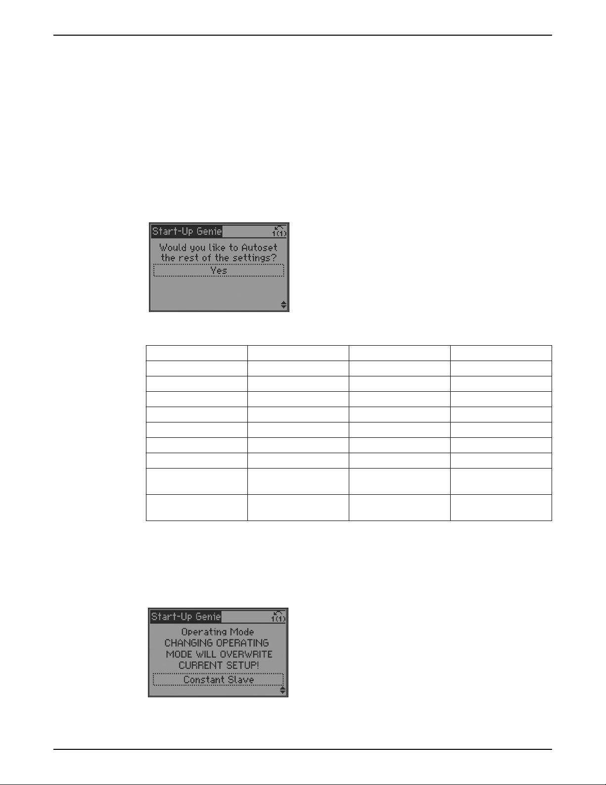
Operation
• A Fast ramp setting will have a 5 second acceleration ramp time and an 8 second
deceleration time.
• A Medium ramp setting will have a 10 second acceleration ramp time and a 10
second deceleration time.
• A Slow ramp setting will have a 20 second acceleration ramp time and a 15 second
deceleration time.
• Acceleration ramps are set in Parameters [3-41] and [3-51]. Deceleration ramps are
set in Parameters [3-42] and [3-52].
The next screen will allow the user to automatically configure the rest of the parameters to
default settings. The only parameter that must be set after selecting [Yes] is the setpoint.
After the setpoint is configured the setup of the controller is complete. The default
configurations are described in the table below. Note that [unit] will reflect the control
units selected previously. If No is selected the Genie will prompt to proceed to the
Feedback Setup.
Constant slave
Table 19: Autoset configuration
Autoset Configuration Constant Pressure Level Control Flow Control
Transducer Max Feedback 300 [unit] 300 [unit] 300 [unit]
Transducer Type 4-20mA 4-20mA 4-20mA
Feedback 1 Source AI 53 AI 53 AI 53
PID Performance Normal Fill (Normal) Normal
Sleep Mode Enabled Enabled Disabled
Sleep Frequency 30 Hz 30 Hz NA
Restart Difference 5 [unit] 5 [unit] NA
No Water/Loss of Prime
Enabled Enabled Enabled
Fault
No Water/Loss of Prime
10 min. 10 min. 10 min.
Restart Time
The Constant Slave Operating Mode allows control of up to 2 external fixed speed pumps
using the 2 on board relays. This mode can be used to extend the capacity of a system by
staging fixed speed pumps as the demand in the system increases. Pumps can then be
destaged as the system demand decreases. The variable speed pump is always the lead
pump. The fixed speed pumps can be staged and destaged to create a lead/lag system.
The Application Type can be set to either Constant Pressure or Level Control. Set control
variable units and ramps as described in Single Pump Operating Mode.
Aquavar® Intelligent Pump Controller INSTRUCTION MANUAL 67
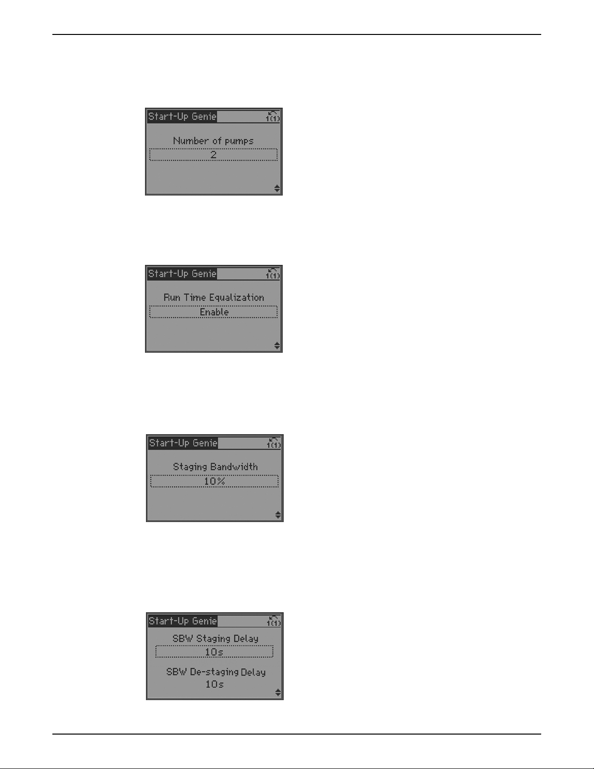
Operation
The next menu prompts the user to set the number of pumps in the system. Enter the
number of pumps in the system, including the variable speed pump. The selection will be
entered in to parameter [25-06] Number of pumps. If 2 pumps are selected, this means
that there is 1 variable speed pump and 1 fixed speed pump in the system. The fixed
speed pump will be controlled by relay 1.
The next menu prompts the user to enable or disable Run Time Equalization [25-04].
When the parameter is disabled the pumps will always be turned on (stage) in the order
of pump 1 then pump 2 and turned off (destage) in the order of pump 2 then pump 1.
Enabling this parameter will stage and destage the fixed speed pumps to provide equal
run time for each fixed speed pump.
The next menu configures the [25-20] Staging Bandwidth. The Staging Bandwidth (SBW)
sets a range around the setpoint in which no staging or destaging of pumps will occur.
This range is set to avoid frequent staging and destaging of pumps and to accommodate
normal fluctuations present in the system. The Staging Bandwidth (SBW) is set as a
percentage of the setpoint. For example if a setpoint of 50 psi is selected, and the SBW is
set to 10% then no staging or destaging of pumps will occur in the range of 45-55 psi.
The next menu configures the staging delay times. These delay times define the length of
time that the system pressure must be outside the SBW before staging or destaging
pumps will occur. For example if the [25-23] SBW Staging Delay is set to 10 seconds and
the system pressure is outside the SBW for more than 10 seconds a fixed pump will be
staged. If the pressure transitions back inside the SBW before the delay time expires, the
timer will reset. Parameter [25-24] SBW Destaging Delay sets the delay time associated
with pumps being destaged.
68 Aquavar® Intelligent Pump Controller INSTRUCTION MANUAL
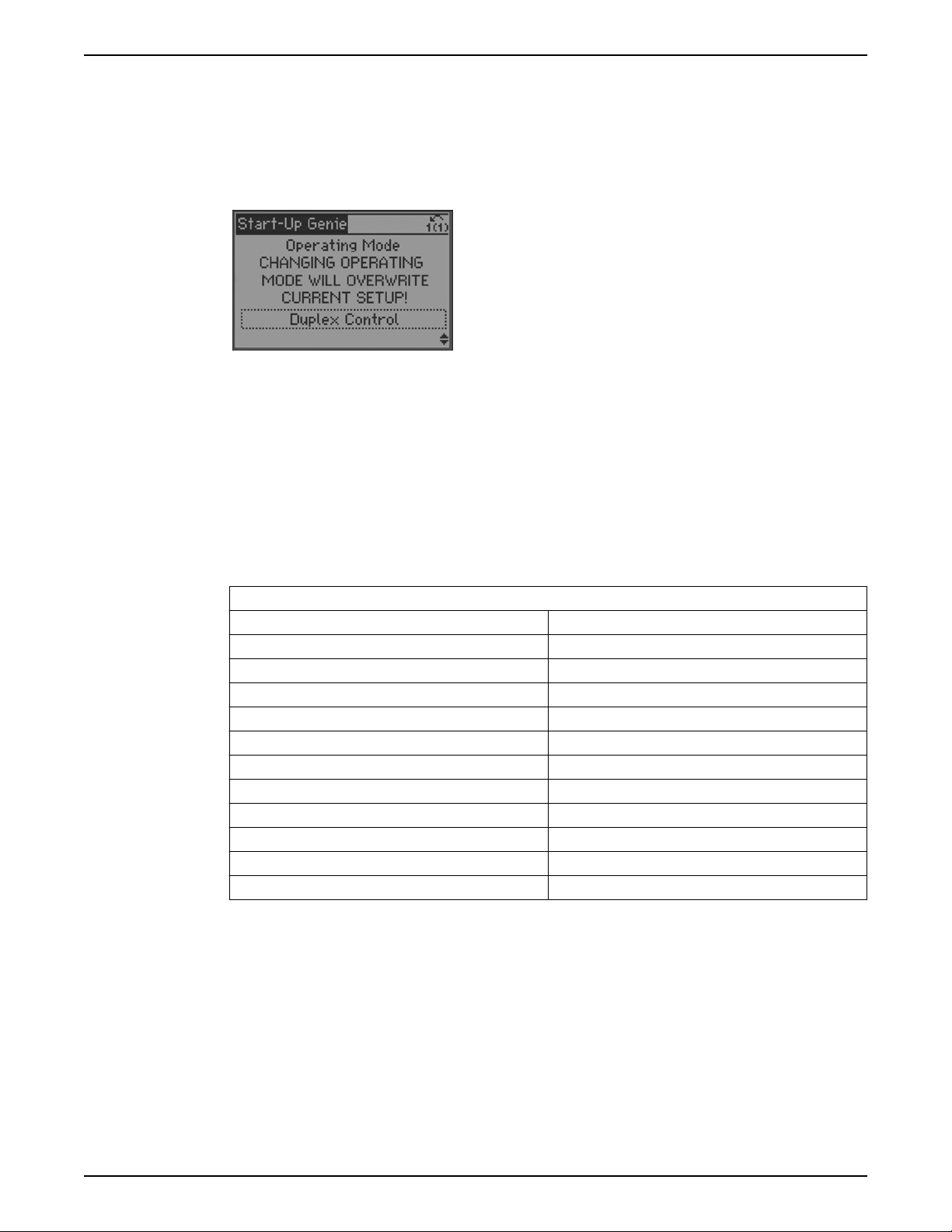
Duplex control
Operation
The Duplex Control Mode configures the controller for operation in a system with 2
controllers and 2 variable speed pumps. Each controller is connected to a single pump.
When configured as a lead/lag system (Duty Standby Disabled) the pumps can be staged
or destaged as the demand requires. When both pumps run at the same time they will
operate at the same speed. The lead controller/pump can be switched/alternated
between the 2 controllers.
NOTE: The Duplex Control Mode requires specific control wiring for proper operation.
Consult the Wiring to Control Terminals section in this manual for details.
NOTE: The Duplex Control Mode requires specific parameter settings to proper
operation. Changing to Duplex Control will overwrite any preconfigured parameters.
As in the previously described application types, the control units and ramp times are
configured first. The next screen allows the user to automatically configure the rest of the
parameters to default settings. The only parameter that must be set after selecting Yes is
the setpoint. After the setpoint is configured the setup of the controller is complete. The
default configurations are described in the table below.
Duty standby
Table 20: Duplex Autoset Configuration
Duplex Autoset Configuration
Transducer Max. Feedback 300 [unit]
Transducer Type 4–20mA
Feedback 1 Source AI 53
Sleep Frequency 30 Hz
Restart Difference 5 [unit]
No Water/Loss of Prime Fault Enabled
Duty Standby Disabled
Lag Start Freq 59 Hz
Lag Stop Freq 35 Hz
Alternation Enabled
Alternate Time 24 Hrs
Pump Exercise Time 0 s (Disabled)
Enabling Duty Standby allows the system to be configured as a 2 pump redundant
system. With Duty Standby enabled both pumps will not run at the same time during
normal operation. Only the lead pump will run when required.
The pumps can be configured to alternate the lead pump by enabling Alternation.
Disabling Duty Standby configures the 2 pump system as a lead/lag system. With Duty
Standby disabled, the pumps can be staged/destaged as required based on system
demand.
NOTE: If Duty Standby is enabled, both pumps may run at the same time during
alternation, after a start command is received or after an alarm is reset depending on the
setting of Start Delay [1-71]. Set the Start Delay [1-71] longer than the Ramp Down Time
[3-42] of the other pump or 3 seconds, whichever is longer, to avoid this condition. Refer
Aquavar® Intelligent Pump Controller INSTRUCTION MANUAL 69
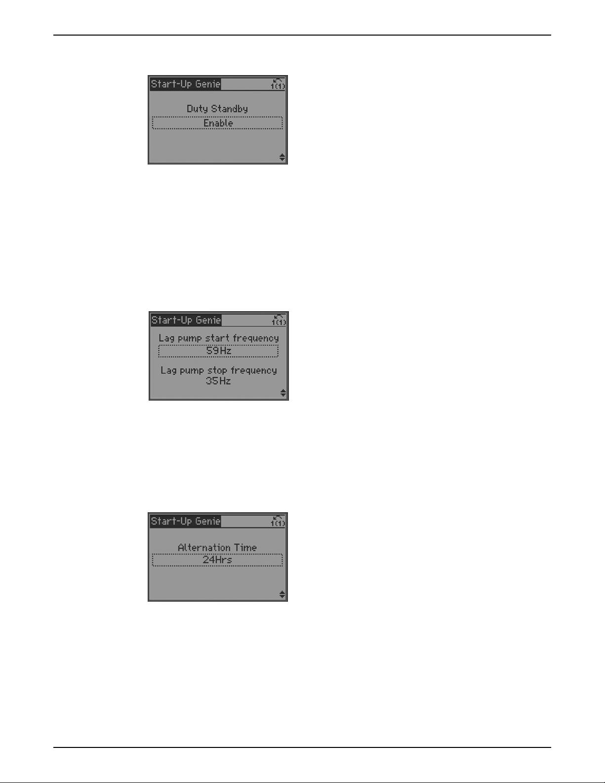
Operation
to Pump Exercise for details on how Duty Standby, Pump Exercise and Start Delay impact
when pumps are expected to run.
Lag pump start frequency and lag pump stop frequency
The Lag Pump Start Frequency and Lag Pump Stop Frequency can be configured to
control the frequency/speed that the lag pump is staged and destaged. This feature is
enabled only when Duty Standby is Disabled. The Lag Pump Start Frequency (staging
frequency) should be set to a frequency close to the maximum speed of the motor/pump.
The default is set to 59Hz with a maximum speed of 60Hz. This will ensure best utilization
of each pump. The Lag Pump Stop Frequency (destaging frequency) should be set to a
frequency above the [4-12] Sleep Frequency/Low Limit [Hz] of the lead pump. For
example, when the [4-12] Sleep Frequency/Low Limit [Hz] is set to 30Hz, the Lag Pump
Stop Frequency should be set to 35Hz. The actual value used depends on system
requirements.
Alternation and alternation time
Enabling Alternation allows the lag pump to become the lead after the Alternation Time
expires. Enabling Alternation allows equalization of loading between the 2 pumps and
controllers. The Alternation Time is based on elapsed time, not pump run time. Because of
this it is recommended to set Alternation Time to a time that is greater than or equal to 24
hours. For example, in a system that has high demand in the morning, setting the
Alternation Time to 24 hours ensures each pump will be the lead pump every other
morning which will equalize the loading between the two pumps.
Note: The lead pump can be manually alternated by pressing the [OK] and right arrow
keys on the lead drive.
Pump exercise
The Pump Exercise Function forces the lead pump to run for a specified time during
lead/lag pump alternation. This function is designed to help prevent the effects that can
occur on a pump as a result of remaining idle for long periods of time. Set the Pump
Exercise Time to the amount of time the new lead pump will run during alternation. For
example, if the Pump Exercise Time is set to 10 seconds, the new lead pump will run for
10 seconds when the lead and lag pumps alternate. Set Pump Exercise Time to 0s to
disable the function.
70 Aquavar® Intelligent Pump Controller INSTRUCTION MANUAL

Operation
NOTE: If Pump Exercise is enabled, the pump will run after alternation of the lead pump
even if there is no demand in the system.
NOTE: If Duty Standby is enabled, Pump Exercise cannot be disabled. Refer to the table
below for details.
The settings for Duty Standby, Pump Exercise and Start Delay can impact when a pump is
expected to start. The table below shows how these settings impact when a pump will
start.
Duty Standby Pump Exercise Explanation
Disabled Disabled If both controls are given a start command at the same
time or both controls are reset from a fault at the same
time, both pumps will run until the lead pump and lag
pump roles are established. With both functions
disabled, the duplex system will operate as a lead/lag
system. On Alternation, the new lead pump will not run
unless there is demand in the system.
Disabled Enabled The lag pump will start when the lead pump wakes up
from sleep or if the lead pump is stopped and is then
given a start command. For these conditions the lag
pump will run for the time specified in Pump Exercise
Time [22-40]. The lag will continue to run if the speed
command from the lead pump is greater than the Lag
Pump Stop Frequency [4-12].
On Alternation, the new lead pump will run for the time
specified in Pump Exercise Time. After the Pump Exercise
Time, the pump will continue to run if demand is present
or will go to sleep if there is no demand.
Enabled Enabled On Alternation and no demand, the new lead pump will
start and run for the time specified by Pump Exercise
Time [22-40] or Sleep Delay [22-24], whichever is longer.
The pump will then go to sleep, if enabled.
On Alternation with demand, the new lead pump will
ramp up while the previous lead pump is ramping down.
In order to ensure both pumps do not run at the same
time in this condition, set the Start Delay [1-71] time
longer than the Ramp Down Time [3-42].
Start delay
The Start Delay Function delays the lead pump from starting for the time specified. This
function can be used to prevent rapid cycling of the system or to prevent the new lead
pump from starting up while the lag pump is ramping down during alternation. For
example, if the Start Delay Time is set to 10 seconds and the pump is given a start
command, the pump will start 10 seconds after the command to start is received by the
controller. In a Duplex System with the Start Delay set to 10 seconds, if Alternation is
enabled and the Alternation Time expires the new lead pump will start after a 10 second
delay. If Duty Standby is enabled, set the Start Delay longer than the Ramp Down Time
[3-42] of the other pump to ensure both pumps do not run at the same time.
Aquavar® Intelligent Pump Controller INSTRUCTION MANUAL 71

Operation
Speed control
Speed Control Mode allows the speed to be controlled by an external device such as a
PLC or BMS. A start signal on DI 18 is required to start and stop the pump.
To configure Speed Control Mode first select the speed reference source. Select the
speed reference source as either an analog input or, if using the fieldbus as the speed
reference source, select No Function. When using the analog inputs be sure to set the
analog input configuration switches to the appropriate feedback type. Refer to the Analog
Input Configuration (Switches A53 and A54) section for details on setting the analog input
configuration switches. Refer to the Common Terminal Wiring Configurations section in
this manual for detail on wiring external devices to the analog inputs.
Next set the minimum and maximum reference/feedback values. The Low Ref./Feedb.
Value is the speed value that corresponds with the low current (0 or 4mA for current
references) or low voltage (0V for voltage references) that will be applied to the analog
input. The High Ref./Feedb. Value is the speed value that corresponds with the high
current (20mA for current references) or high voltage (10V for voltage references) that will
be applied to the analog input. For example, if the application uses a 4-20mA reference
signal on AI 53 and the pump is required to operate from 30Hz to 60Hz, set [6-14]
Terminal 53 Low Ref./Feedb. Value to 30 and [6-15] Terminal 53 High Ref./Feedb. Value to
60.
The minimum and maximum speed reference values are set next. These values are the
minimum and maximum speed settings for the application. These settings will limit the
controllable speed range of the pump. The speed range will be limited to the Minimum
Speed Reference as the low speed limit and Maximum Speed Reference as the high speed
72 Aquavar® Intelligent Pump Controller INSTRUCTION MANUAL

Test run mode
Operation
limit. Using the example above, set the Minimum Speed Reference to 30Hz and the
Maximum Speed Reference to 60Hz.
Test Run Mode allows the controller to perform a test which will ramp the pump at a
specified speed in order to perform a test on the system and pump/motor. Test Run
Mode is triggered to start based on the state of DI 18. When DI 18 is closed, the test will
begin. When DI 18 is open, test run mode will stop. To configure Test Run Mode set the
test run speed and test run ramp time. The Test Run Speed is the speed that the controller
will ramp the pump to. The Test Run Ramp Time is the ramp used to reach the Test Run
Speed. This ramp is the time to ramp from stop (0 RPM) and the rated motor speed. The
Test Run Ramp Time applies to both acceleration and deceleration in Test Run Mode.
Feedback setup
The controller can utilize up to 3 feedback sources using the onboard IO. 2 of these
sources can be
configured for the analog inputs (AI 53 and AI 54). The third can be set to
bus feedback which can be set through the onboard fieldbus communications.
When using analog inputs be sure to set the analog input configuration switches to the
appropriate feedback type. Refer to the Analog Input Configuration (Switches A53 and
A54) section for details on setting the analog input configuration switches. Refer to the
Common Terminal Wiring Configurations section in this manual for detail on wiring
external devices to the analog inputs.
If multiple feedback sources are selected then the Feedback Function [20-20] can be
configured. The Feedback Function determines how the multiple feedbacks will be used
to control the system.
Aquavar® Intelligent Pump Controller INSTRUCTION MANUAL 73

Operation
Feedback function [20–20]
Sum The sum of all feedbacks will be in the feedback to the
controller.
Difference The difference between Feedback 1 and Feedback 2 will
be the feedback to the controller. This setting is
commonly used to configure a differential pressure
signal using 2 separate transducers. NOTE This selection
is only valid with Feedback 1 and Feedback 2. Feedback 3
is not used with this selection.
Average The average of all feedback will be the feedback to the
controller.
Minimum The lowest feedback will be the feedback to the
controller.
Maximum The highest feedback will be the feedback to the
controller.
The minimum and maximum values for each feedback source must be configured to
properly scale the input. For example, for a 0-300 psi transducer, set the Low Feedback
Value to 0 psi and the High Feedback Value to 300 psi.
Setpoint setup
A Sensor Fault can be enabled or disabled for each feedback. If the Sensor Fault is
enabled and the input to the feedback source falls below 2mA for 4-20mA signals, the
Sensor Fault is issued. The Sensor Fault will automatically restart according to [14-20]
Reset Mode and [14-21] Automatic Restart Time. The defaults for these parameters are set
for an Automatic reset x 3 and an Automatic Restart Time of 10 seconds. For example,
with the default settings if a Sensor Fault is issued the controller will attempt to reset every
10 seconds. The controller will make 3 attempts to reset the fault. If the fault is not cleared
in this time the controller will require a manual reset.
The controller can be
configured to switch between 2 different setpoints. The setpoints
will be selected through digital input 33 (DI 33, parameter 5-15). When parameter 5-15 is
set to SP1/SP2 and DI 33 is open, the controller will use SP1 (Setpoint 1 [20-21] Setup 1) as
the target pressure, flow or level for the system. When parameter 5-15 is set to SP1/SP2
and DI 33 is closed (connected to 24V), the controller will use SP2 (Setpoint 1 [20-21]
Setup 2) as the target pressure, flow or level for the system.
74 Aquavar® Intelligent Pump Controller INSTRUCTION MANUAL

Flow compensation setup
As flow in a pumping system increases, the system friction head losses also increase.
Friction head loss is higher in systems with increased pipe lengths or decreased pipe size.
The impact of this head loss is that the pressure at different points in the system will vary
depending on flow rate and the distance from the pump. The loss will be most significant
in the zones farthest from the pump. The controller’s internal Flow Compensation function
is used to correct the effect of friction head loss in the system. The flow compensation
function calculates a control curve based on pump and system parameters. The controller
actively adjusts the setpoint along the control curve based on the speed of the pump.
Since a change in speed is proportional to a change in flow, the controller effectively
adjusts the setpoint based on a change in speed. A change in pressure varies with the
square of the change in speed or flow so a quadratic (square) compensation factor is used
to adjust the setpoint. Parameter [22-81] Square-linear Curve Approximation can be
modified to adjust the control curve between a linear (0%) and quadratic (100%). Note
that 100% quadratic is the ideal compensation curve. The diagram below illustrates this
concept. The rating curve is the pump performance curve at rated speed. The design
curve is the system curve at design speed.
Operation
Figure 31: Flow compensation control curve
The flow compensation function requires some system parameters to be set in the
controller to accurately model the control curve. Parameters must be set based on the
design of the system in order to properly configure this function. The parameters that are
required to be configured will depend on whether the speed at the design point is
known. If the speed at the design point is known, set [22-82] Work Point Calculation to
disabled. Set the [22-84] Speed at No Flow [Hz] and [22-87] Pressure at No-Flow Speed,
which correlate to point A on the diagram below. The intersection of the system [20-21]
Setpoint and [22-86] Speed at Design Point [Hz]correlates with point B. With this
information the controller can then calculate the control curve. Refer to the diagram
below.
Aquavar® Intelligent Pump Controller INSTRUCTION MANUAL 75

Operation
Figure 32: Flow compensation when speed at system design working point is known
Table 21: Flow compensation parameters when speed at design point is known
Parameter Number Description Set to
22–80 Flow Compensation Enabled
22–81 Square-Linear Curve Approximation Modify between 100% (square) and
0% (linear) per system requirements.
22–82 Work Point Calculation Disabled — speed at the design point
is known
22–84 Speed at No Flow [Hz] To find this point, close all of the
discharge valves in the system and
briefly run the pump at the minimum
design head. The speed
corresponding to the minimum head
requirement at no flow will be
entered here.
22–86 Speed at Design Point [Hz] These setpoints correspond to the
speed required to maintain point B
(design head {[20–21] Setpoint) and
design flow)
22–87 Pressure at No Flow System pressure at no flow and no
flow speed. This is the minimum
design head.
If the speed at the design point is unknown, the [22-82] Work Point Calculation must be
enabled. With the [22-82] Work Point Calculation enabled the controller will calculate the
speed at the design point based on settings of some additional parameters correlating to
the points shown on the diagram below. The first point determined is point A which is the
minimum required head at minimum speed ([22-84] Speed at No Flow [Hz] and [22-87]
Pressure at No-Flow Speed). Points C and D can be determined by consulting the pump
performance curve. Point C is determined by extending the design [20-21] Setpoint line
horizontally to intersect the rated curve which is the pump performance curve at rated
speed (usually 50 or 60Hz). The flow at this point (Q
Speed. Point D is determined by extending the design flow point (Q
) is set in [22-90] Flow at Rated
Rated
) vertically to
Design
intersect the rated speed curve. The head generated at this flow and speed is set at
[22-88] Pressure at Rated Speed. Knowing points A, C and D allow the controller to
calculate point E along with the control curve which includes point B (speed, pressure and
flow at design speed). Refer to the diagram below.
76 Aquavar® Intelligent Pump Controller INSTRUCTION MANUAL

Operation
Figure 33: Flow compensation when speed at design working point is unknown
Table 22: Flow compensation parameters when speed at design point is unknown
Parameter Number Description Set to
22–80 Flow Compensation Enabled
22–81 Square-Linear Curve Approximation Modify between 100% (square) and
0% (linear) per system requirements.
22–82 Work Point Calculation Enabled — speed at design point is
unknown
22–84 Speed at No Flow [Hz] To find this point, close all valves in
the system and run the pump at the
minimum head. The speed
corresponding to the minimum head
requirement at no flow will be
entered here. Point A.
22–87 Pressure at No Flow System pressure at no flow and no
flow speed. This is the minimum
design head. Point A.
22–88 Pressure at Rated Speed This setting corresponds to the head
developed at design flow and rated
speed. This value can be defined
using the pump performance curve.
Intersects with the design flow to
form point D.
22–89 Flow at Design Point This setting corresponds to the
system design flow. Intersects with
the pressure at rated speed to form
point D and with the setpoint to form
point B.
22–90 Flow at Rated Speed This setting corresponds to the flow at
rated speed. This value can be
defined using the pump performance
curve. Intersects with the setpoint to
form point C.
Dual pump value increase
In a Duplex Control System the friction losses can increase when both the lead and lag
pumps are running due to the additional flow in the system. When both pumps are
running, the Rated Curve and Design Curve shown above will change (reach higher flows
at a given pressure) when compared to when a single pump is running. This means that
the settings given to configure the Flow Compensation function may not be accurate
when both pumps are running. The Dual Pump Value Increase setting applies an increase
to the setpoint which will offset the additional losses associated with both pumps running.
Aquavar® Intelligent Pump Controller INSTRUCTION MANUAL 77
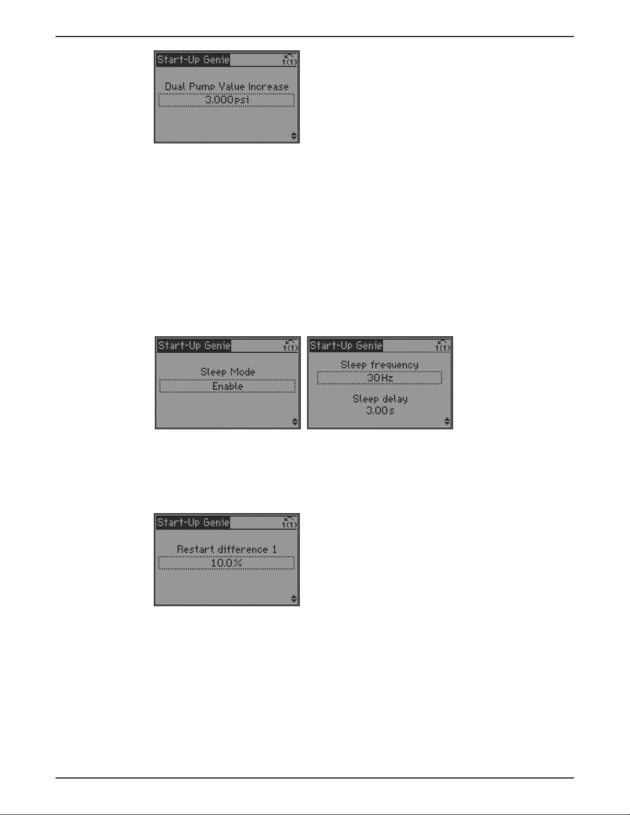
Operation
NOTE: This function is not intended for substitution of proper pipe layout and sizing
according to Hydraulic Institute Standards.
Pump protection setup
Sleep mode
Sleep Mode protects the pump by turning off the pump in cases where there is no flow in
the system. Sleep mode can be enabled or disabled. If Sleep Mode is disabled the pump
will not turn off during a no flow condition if no other control devices are present to turn
the pump off. The Sleep Frequency/Low Limit [4-12] and Sleep Delay [22-24] are set first.
The Sleep Frequency/Low Limit [4-12] is the frequency that the pump has to reach or fall
below in order to enter sleep mode. The Sleep Frequency is also the minimum frequency.
The Sleep Delay is the amount of time the pump speed must be at or below the Sleep
Frequency in order to enter Sleep Mode. Use this parameter to prevent the pump from
entering sleep mode too soon.
The Restart Difference [22-44] is the difference between the setpoint and the actual value
that will cause the pump to restart (wake up) from sleep mode. This value is entered as a
percent of the setpoint. For example, if the setpoint is 50 psi and a 10% Restart Difference
is entered the pump will restart from sleep mode after the system pressure drops 5 psi
below the set pressure (45 psi). If multiple setpoints are used then a Restart Difference
must be entered for each setpoint.
The Minimum Run Time [22-40] and Minimum Sleep Time [22-41] can be used to prevent
rapid cycling. The Minimum Run Time [22-40] forces the pump to stay on and not enter
sleep mode until the pump runs for the time entered in Minimum Run Time [22-40]. The
Minimum Sleep Time [22-41] forces the pump to stay in sleep mode (turned off) for the
time entered in Minimum Sleep Time [22-41].
78 Aquavar® Intelligent Pump Controller INSTRUCTION MANUAL
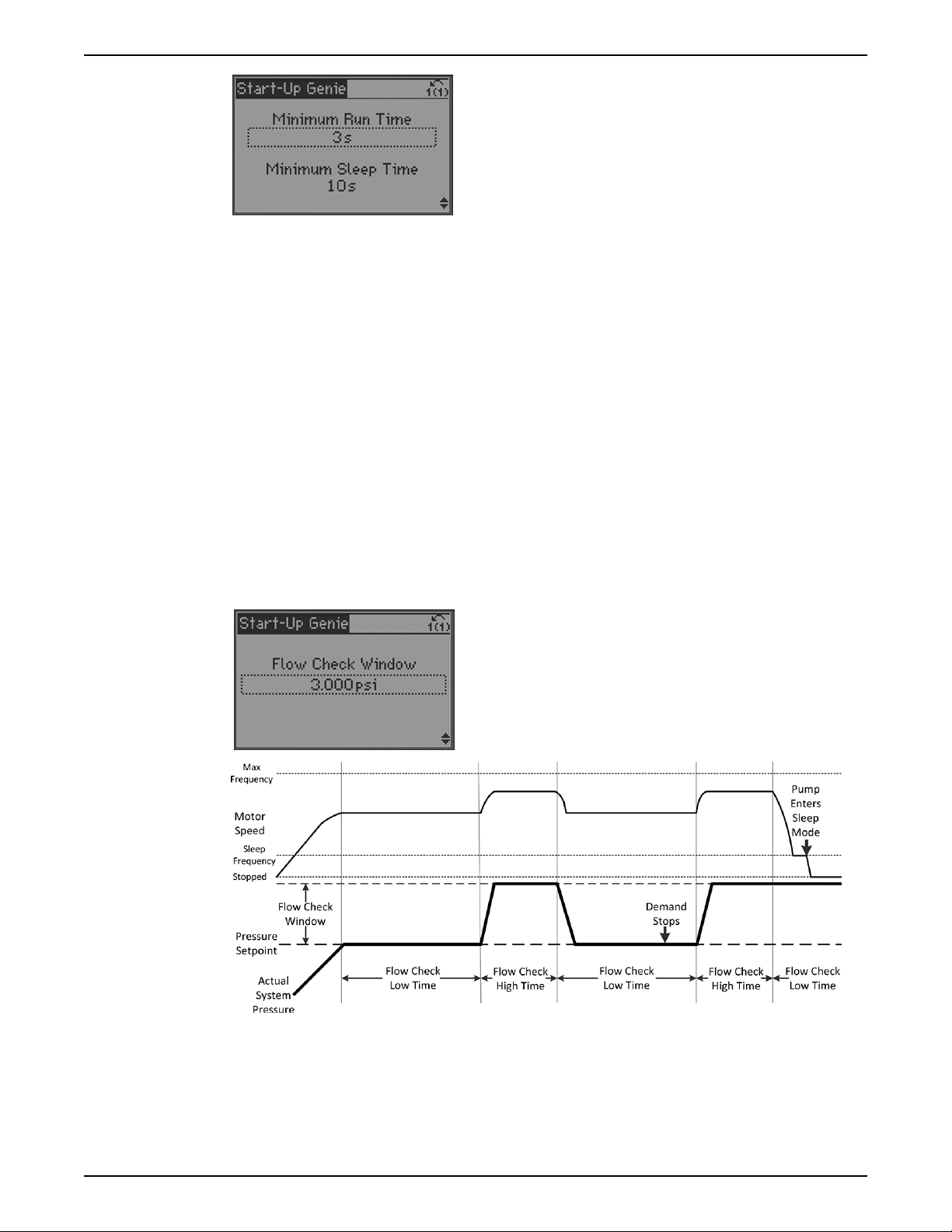
Flow check
Operation
The Setpoint Boost [22-45] function can be used to further reduce cycle time. The Setpoint
Boost function increases the system pressure before the pump enters sleep mode. To
configure this function, exit the Genie and enter the parameter list by pressing the [Main
Menu] key. Set parameter [22-45] Setpoint Boost and [22-46] Maximum Boost Time.
Setpoint Boost [22-45] is the amount of increase in system pressure desired before the
pump enters sleep mode. This is entered as a percent of setpoint. The Maximum Boost
Time is a timeout function used to ensure the pump enters sleep mode. If the pump
cannot achieve the setpoint + Setpoint Boost pressure before the Maximum Boost Time
expires, the pump will enter sleep mode.
The Flow Check function performs a test to determine whether flow or demand exists in
the system. If a no flow condition exists in the system the pump will ramp down to Sleep
Frequency and enter sleep mode. The Flow Check function is performed only when the
pump is running. A diagram showing the Flow Check function is shown below. Motor
speed is shown to illustrate the pump reaction to the Flow Check function. As shown in
the diagram, when demand (flow) stops, the Flow Check function forces the system
pressure to be higher than the Pressure Setpoint which forces the pump to enter sleep
mode.
NOTE: This function is not available in Duplex Control mode.
To configure the Flow Check function first set the Flow Check Window. The Flow Check
Window is the amount of pressure increase that will be used during the Flow Check
function test. This amount is added to the existing setpoint to create a new temporary
setpoint. Next set the Flow Check Low Time and the Flow Check High Time. The Flow
Check Low Time defines how long the controller will run at the setpoint before applying
the value set in Flow Check Window. The Flow Check High Time defines how long the
controller will run at setpoint plus the value set in Flow Check Window. These times are
Aquavar® Intelligent Pump Controller INSTRUCTION MANUAL 79
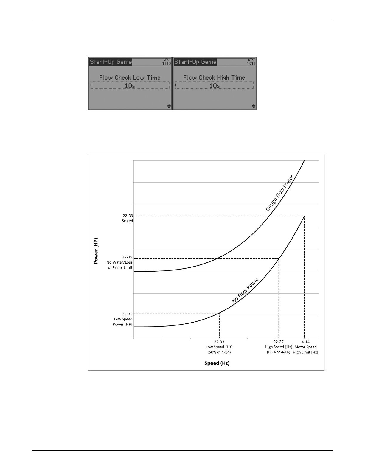
Operation
limited between 10 and 300 seconds. Ensure Flow Check Low Time is set long enough to
allow the pump to ramp down to the sleep frequency. Setting the Flow Check Low Time
longer or equal to the Ramp Down Time [3-42] will ensure the pump has time to ramp to
sleep during the Flow Check Low Time.
No Flow Power Calibration
A no flow condition can also be detected by monitoring the power consumption of the
pump. Typically a pump’s power consumption will drop when the pump is run at no flow.
The graph shown below illustrates a typical pump power curve at the pump design flow
and at no flow.
When the pump is operated at no flow, the power consumption will follow the no flow
power curve for that specific pump. The controller monitors the power consumption of
the pump. If the pump’s power consumption falls to the no flow power curve, a no flow
condition can be detected by the controller. In order to detect a no flow condition for
various pumps, the no flow power curve needs to be programmed in to the drive. The No
Flow Power Calibration Setup provides the method to program the no flow power curve
in to the controller.
80 Aquavar® Intelligent Pump Controller INSTRUCTION MANUAL
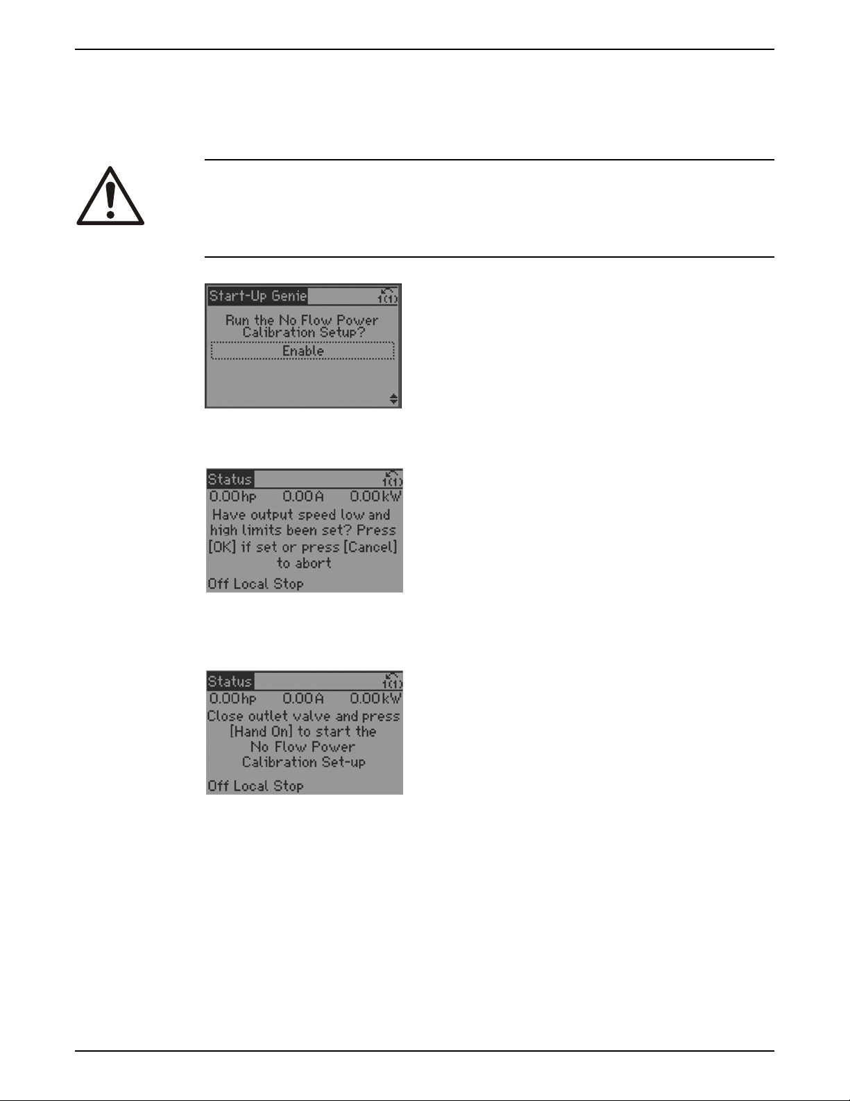
Operation
NOTE: Before beginning the No Flow Power Calibration Process ensure the Sleep
Frequency/Low Limit [4-12] and the Motor Speed High Limit [Hz] [4-14] are set. These
parameters are set as part of the Motor Setup.
NOTE: For the most accurate No-Flow Power Calibration data, run the setup after the
system has reached normal operating temperature.
WARNING:
The No Flow Power Calibration Process requires the pump to be operated at no flow. This
can produce high pressure within the system. Ensure the system piping and components
are designed to withstand the suction pressure plus shutoff head pressure produced by
the pump prior to starting the calibration process.
Select Enabled to begin the No Flow Power Calibration Setup.
The first screen prompts to ensure the Sleep Frequency/Low Limit [4-12] and Motor Speed
High Limit [4-14] have been set. If these points are not set the No Flow Power Calibration
will not operate properly.
The next screen prompts to close all discharge valves and to press [Hand On] to begin the
No Flow Power Calibration process. Doing this ensures the pump will operate at no flow/
shutoff. If the pump does not operate at no flow during the setup, the calibration data will
be invalid.
The controller will now begin running the pump while monitoring the power. In the first
two steps the pump is operated at 85% of maximum speed defined at Motor Speed High
Limit [Hz] [4-14] and the power to the pump is monitored and saved. The pump then
operates at 50% of maximum speed and the power is monitored and saved. The no flow
power curve is then constructed within the controller based on these 2 points using the
affinity laws.
The No Flow Power Calibration Set-up is now complete. The power data can be saved by
pressing [OK] and then the down arrow. If any issues were encountered during the
calibration process discard the data by pressing [Cancel] and repeat the calibration
process.
Aquavar® Intelligent Pump Controller INSTRUCTION MANUAL 81
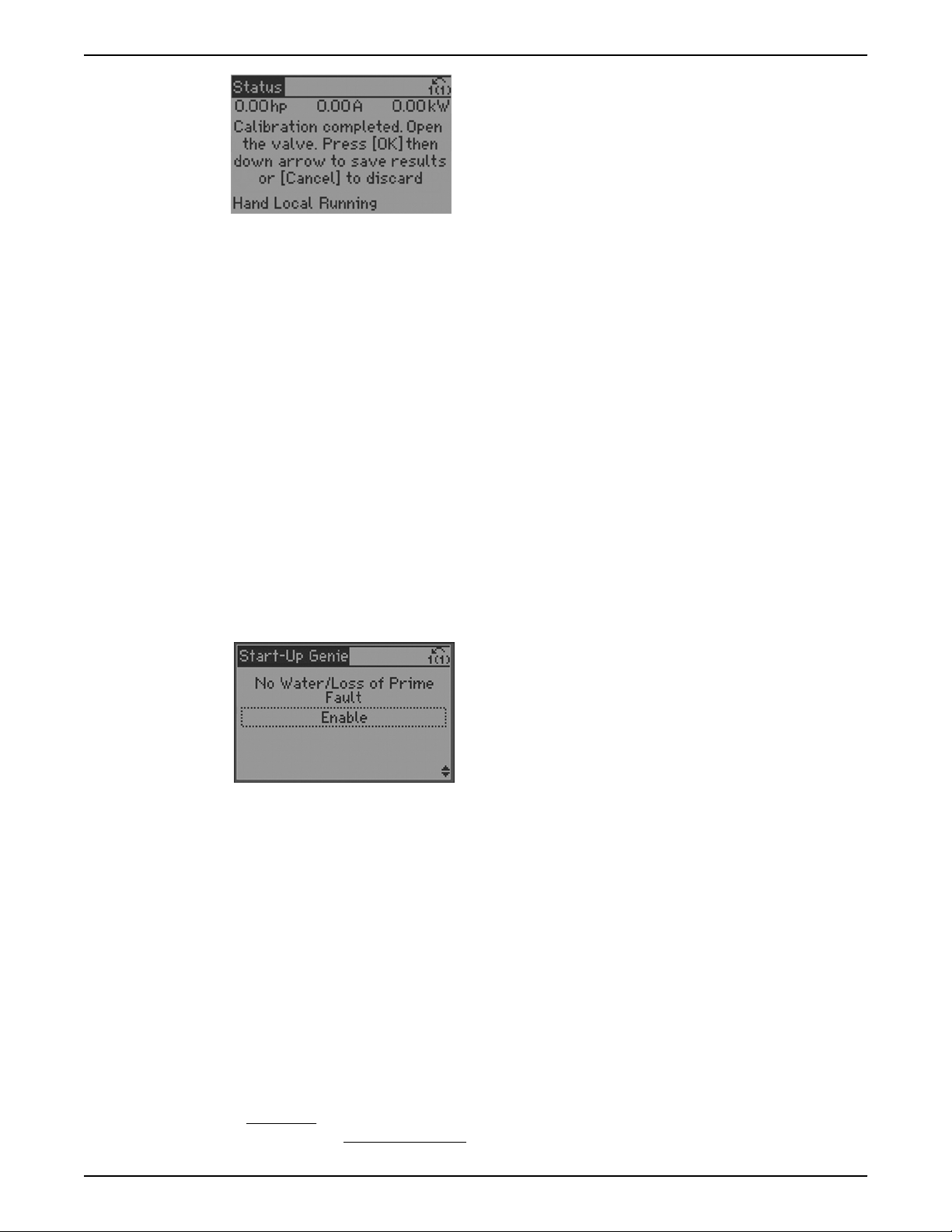
Operation
NOTE: Be sure to press [OK] then the down arrow to save the No Flow Power Calibration
data. Pressing the down arrow ensures that all background calculations and parameter
settings are performed properly.
NOTE: The No Flow Power Calibration Set-up configures the No Water/Loss of Prime Limit
[22-39]. Do not modify the No Water/Loss of Prime Limit after the No Flow Power
Calibration Set-up is completed. Modification of the No Water/Loss of Prime Limit [22-39]
can cause the No Flow detection and No Water/Loss of Prime detection to malfunction.
In some cases the power calculation based on the calibration data taken during the No
Flow Power Calibration Set-up may require adjustment. The Power Correction Factor
[22-31] parameter allows the calculated power to be adjusted to avoid detection of a no
flow condition while there is flow or to allow detection of a no flow condition while there is
no flow in the system. If a no flow condition is detected while there is flow, the setting
should be decreased. If a no flow condition is not detected while there is no flow, the
setting should be increased above 100%.
No water/loss of prime
The No Water/Loss of Prime function is used to protect the pump against running dry
and/or loss of prime. The function works by monitoring power at full speed and
comparing the actual power to a preset limit. If the actual power falls below this preset
limit for a specified amount of time, the No Water/Loss of Prime alarm is issued. If the No
Water/Loss of Prime function is disabled, the pump will not be protected against running
dry and/or loss of prime.
NOTE: In Duplex Control the No Water/Loss of Prime function is disabled by default on
the lag pump. In Duplex Systems where pumps are fed from different sources the lag
pump should be protected by using the Pump Protect Function. Refer to the Pump
Protect Function for details.
NOTE: In Duplex Systems where pumps are fed from different sources and the lag pump
is able to maintain the system pressure without reaching maximum speed, the No Water/
Loss of Prime condition may not be detected on the lead pump. In this case it is
recommended to delay the starting of the lag pump by setting the Minimum Sleep Time
[22-41] on the lag pump greater than the No Water/Loss of Prime Protection Delay [22-27]
plus the Ramp Up Time [3-41] of the lead pump. Be sure to set this on both controllers
while set to lag if alternation is enabled.
The No Water/Loss of Prime Limit [22-39] is the no flow power value that corresponds to
the speed entered in High Speed [Hz] [22-37]. The No Flow Power Calibration Set-up
automatically enters 85% of the Motor Speed High Limit [Hz] [4-14] in High Speed [Hz]
[22-37].
The No Water/Loss of Prime function works by monitoring the pump power consumption
at full speed, and the No Water/Loss of Prime Limit [22-39] corresponds the pump power
consumption at 85% of full speed. The controller internally scales the No Water/Loss of
82 Aquavar® Intelligent Pump Controller INSTRUCTION MANUAL

Operation
Prime Limit [22-39] based on the affinity laws to determine the actual power limit for the
No Water/Loss of Prime function. Since pump power consumption changes with the cube
of speed and the No Water/Loss of Prime Limit is entered as 85% of maximum speed, the
controller scales the power entered in No Water/Loss of Prime Limit [22-39] by (1/85%)3 or
1.628 to determine the actual power limit used for the No Water/Loss of Prime function.
When the pump is running at full speed and the actual power consumed by the pump is
less than or equal to this value for a specified amount of time, the No Water/Loss of Prime
alarm is issued. It is recommended to set this value by performing the No-Flow Power
Calibration Setup.
NOTE: If the Autoset function is used to configure the controller this value is set to 75% of
the service factor HP multiplied by the 85% speed ratio cubed (or (85%)3 = 0.614) of the
pump/motor combination. For example, for a 10HP pump/motor with a pump/motor
service factor of 1.15 (the pump utilizes 100% of the service factor of the motor), the
Autoset function sets the No Water/Loss of Prime Limit [22-39] to 5.29HP.
The Power Correction Factor [22-31] can be used to modify the internal scaling of the No
Water/Loss of Prime Limit [22-39] in cases where nuisance tripping results or where a No
Water/Loss of Prime condition is not detected. If nuisance tripping results, the Power
Correction Factor [22-31] can be increased above 100%. Increasing the Power Correction
Factor [22-31] will increase the scaling of the No Water/Loss of Prime Limit [22-39] so that
a No Water/Loss of Prime condition is detected at a higher power. The amount of increase
above 100% is dependent on the loading of the pump. If a No Water/Loss of Prime alarm
is not issued when the pump has lost prime or runs dry the Power Correction Factor
[22-31] can be decreased so that a No Water/Loss of Prime condition is detected at a
lower power. The amount of decrease below 100% is dependent on the loading of the
pump.
The No Water/Loss of Prime Restart function can be set to allow the controller to attempt
to restart the pump after a specified amount of time. In order to enable this function a
jumper wire must be installed between terminals 29 and 32. Refer to the Common
terminal wiring configurations section in this manual for details on control terminal wiring.
The default restart time is 10 minutes. Set this value based on the system requirements.
The No Water/Loss of Prime Protection Delay [22-27] is the time delay between detection
of the No Water/Loss of Prime condition and the action of the No Water/Loss of Prime
Alarm. The No Water/Loss of Prime Protection Delay [22-27] time can be extended to
avoid nuisance tripping. Note that extending the time will allow the pump to run dry or
without prime for the time specified.
NOTE: It is recommended to set the No Water/Loss of Prime Protection Delay [22-27] time
shorter than the Under Pressure Delay Time [22-51]. This ensures a No Water/Loss of
Prime condition will be detected properly before the Under Pressure function is triggered.
Aquavar® Intelligent Pump Controller INSTRUCTION MANUAL 83
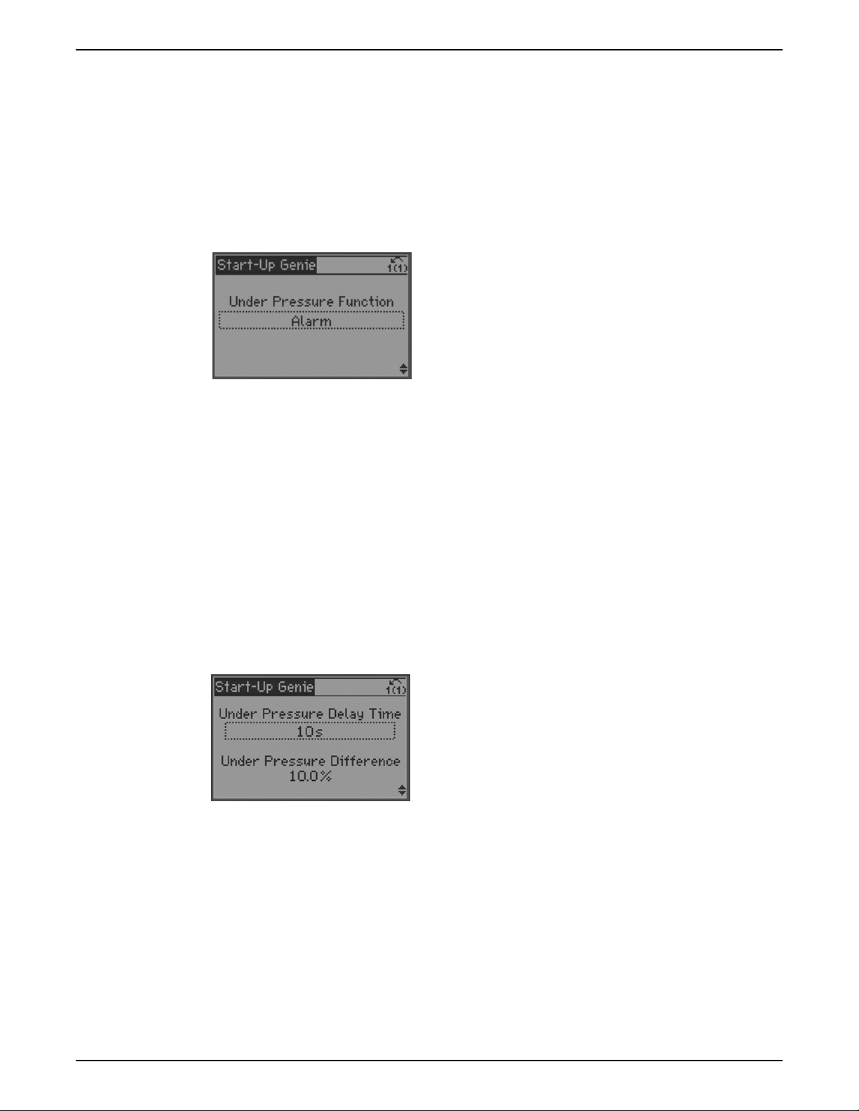
Operation
Under pressure function
The Under Pressure Function protects the pump and system by preventing the pump
from running below a specified low pressure for a specified amount of time. This function
can protect the pump from damage caused by running at runout flow and/or can protect
the system from unexpected leakage such as from an open valve or ruptured pipe. Set the
function to Alarm to trip the drive and issue an alarm message on the LCP during an
Under Pressure condition. Set the function to Warning to issue a warning message on the
LCP during an Under Pressure condition. Set the function to Off to disable the function.
NOTE: The Under Pressure Alarm will reset according to Reset Mode [14-20] and
Automatic Restart Time [14-21].
To configure this function the Under Pressure Delay Time [22-51] and Under Pressure
Difference [22-52] must be set. The Under Pressure Delay Time [22-51] is the amount of
time that the system pressure must be below the Under Pressure Difference [22-52] before
issuing the Under Pressure alarm or warning.
NOTE: Setting the Under Pressure Delay Time [22-51] less than the No Water/Loss of
Prime Protection Delay [22-27] will cause the Under Pressure Alarm to trip before the No
Water/Loss of Prime Alarm in cases where the pressure drop in the system is due to the
pump running dry or losing prime. To avoid this set the Under Pressure Delay Time
[22-51] longer than the No Water/Loss of Prime Protection Delay [22-27].
The Under Pressure Difference [22-52] is the difference between the setpoint pressure the
actual pressure that will trigger the Under Pressure function. This pressure is set as a
percent of the [20-14] Maximum Reference/Feedback. For example, the Under Pressure
Delay Time [22-51] is set to 10 seconds, the Under Pressure Difference [22-52] is set to
10%, the pressure setpoint is set to 50 psi and the [20-14] Maximum Reference/Feedback
is set to 300 psi. If the system pressure falls below 20 psi (50 psi – (10% * 300 psi)) for
more than 10 seconds, the controller will issue an Under Pressure Alarm or Warning.
Pump protect function
The Pump Protect Function provides a way to stop the pump based on the state of an
external protection device. The external device must be wired to DI 19 (parameter 5-11)
or DI 27 (parameter 5-12), refer to the Common Terminal Wiring section in this manual for
details. One side of the external device must be wired to 24V (terminals 12 or 13) and the
other is wired to the digital input (terminal 19 for digital input 19 or terminal 27 for digital
input 27). Refer to the Common terminal wiring
configurations section in this manual for
details on control terminal wiring.
84 Aquavar® Intelligent Pump Controller INSTRUCTION MANUAL
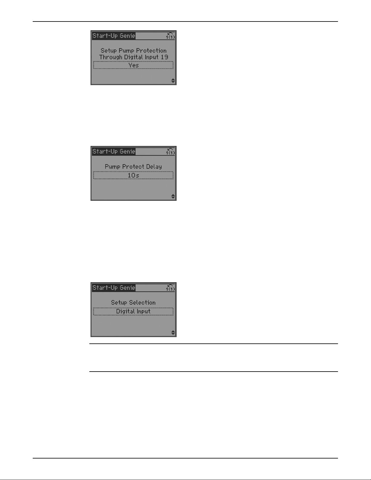
Operation
NOTE: Only connect external devices with non-powered contacts to the digital inputs.
NOTE: Only DI 19 is available for the Pump Protect Function in Duplex Control.
The Pump Protect Delay [22-00] time can be configured to prevent false or nuisance
tripping or the Pump Protect warning or alarm. When Pump Protect is enabled and the
corresponding digital input is open for more than the time indicated in Pump Protect
Delay [22-00], the Pump Protect warning or alarm is issued. The same delay time is used
for Pump Protect on DI 19 and DI 27.
The Pump Protect alarm will reset according to Reset Mode [14-20] and Automatic Restart
Time [14-21].
Digital input setup
Any unused digital input can be configured as part of the Digital Input Setup. A list of the
digital inputs and their associated functions are shown below. The default function of a
digital input can change based on the Operating Mode selected. Digital Input 18 is
utilized as a Start function for all operating modes. This input has a dedicated function and
cannot be configured in the Digital Input Setup. A separate table is given for the Duplex
Control mode due to the specific functionality assigned to the digital inputs.
NOTICE:
Changing the function of any assigned digital input or output when set to Duplex Control
Mode will cause the controller to malfunction.
Aquavar® Intelligent Pump Controller INSTRUCTION MANUAL 85

Operation
Table 23: Digital input functionality based on operating mode
Digital I/O Operating Mode
Terminal Number Parameter
Number
Single Pump/
Constant Slave
Speed Control Test Run Mode Description
18 5–10 [8] Start [8] Start [14] Jog Start/Stop digital
input signal for
the drive. Connect
input to 24 V to
start. Open the
input to stop. This
is a required
connection. In
Test Run Mode,
this input starts
the test run.
19 5–11 [0] No Operation [0] No Operation [0] No Operation Unused digital
input. This input
can be configured
for use as a Pump
Protect Warning
or Alarm Input.
See Pump Protect
section to enable
the Warning or
Alarm associated
with the input.
27 5–12 [0] No Operation [0] No Operation [0] No Operation Unused digital
input for all
models. This
input can be
configured for use
as a Pump Protect
Warning or Alarm
input. See Pump
Protect section to
enable the
Warning or Alarm
associated with
this input.
29 5–13/5–31 [63] No Water/
Loss of Prime
Restart (CMP3)
[0] No Operation [0] No Operation Selectable for
digital input or
output. Default
configuration is
an output that is
configured for use
as a No Water/
Loss of Prime
Restart signal in
the Single Pump
and Constant
Slave mode. Refer
to the Pump
Protection section
for details.
86 Aquavar® Intelligent Pump Controller INSTRUCTION MANUAL

Operation
Digital I/O Operating Mode
Terminal Number Parameter
Number
Single Pump/
Constant Slave
Speed Control Test Run Mode Description
32 5–14 [1] Restart [0] No Operation [0] No Operation Configured for
use as a Reset for
the No Water/Loss
of Prime Restart
function for
Single Pump and
Constant Slave
modes. Refer to
the Pump
Protection section
for details.
33 5–15 [23] SP1/SP2
Select
[23] SP1/SP2
Select
[23] SP1/SP2
Select
Digital input.
Configured for
use as a Setpoint
1/Setpoint 2
select (SP1/SP2)
20 — Common Common Common Common for
digital inputs and
reference for 24 V
supply
Table 24: Digital input functionality based for duplex mode
Digital I/O Duplex Control Mode
Terminal Number Parameter Number Lead Lag Description
18 5–10 [8] Start [8] Start Start/Stop digital
input signal for the
drive. Connect input
to 24 V to start. Open
the input to stop. This
is a required
connection.
19 5–11 [0] No Operation [0] No Operation Unused digital input.
This input can be
configured for use as
a Pump Protect
Warning or Alarm
input. See Pump
Protect section to
enable the Warning
or Alarm associated
with this input.
Aquavar® Intelligent Pump Controller INSTRUCTION MANUAL 87

Operation
Digital I/O Duplex Control Mode
Terminal Number Parameter Number Lead Lag Description
27 5–12 Setpoint increase Pump Exercise Input When operating as
the lead pump, this
input will increase the
setpoint when both
pumps are on to
compensate for the
additional flow of the
lag pump. This
effectively performs a
flow compensation
function. When
operating as a lag
pump, this input acts
as the Pump Exercise
Input which will
perform the Pump
Exercise function. See
Duplex Control in the
Commissioning
section of this manual
for details.
29 5–13/5–31 I am Lead I am Lead Inverse Terminal 29 is
configured as an
output. This output is
used to indicate
which controller is the
lead pump and which
is the lag pump.
32 5–14 Slave Select Slave Select When this input is
high, the other
controller is operating
as the lead pump.
When high, this input
will force the
controller to become
the lag pump or enter
sleep mode if Duty
Standby is enabled.
33 5–15 [23] SP1/SP2 Select [23] SP1/SP2 Select Digital input.
Configured for use as
a Setpoint 1/Setpoint
2 select (SP1/SP2).
Open = SP1, Closed
= SP2.
20 — Common Common supply
Relay and analog output setup
The Relay and Analog Output Setup allows configuration of the onboard relays and
analog output signal.
88 Aquavar® Intelligent Pump Controller INSTRUCTION MANUAL
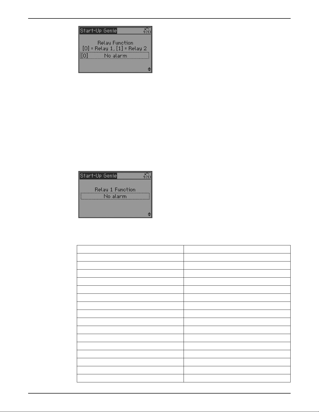
Relay outputs
this image should
replace the next
one
replace this
with one
above
Operation
NOTE: If Constant Slave Mode is enabled the relays are used to control the fixed speed
pumps. Changing the relay function with Constant Slave Mode enabled can cause the
Constant Slave Controller to malfunction.
To configure the relay set the relay function and the relay on delay. The relay function
configures when the relay will change state. For example, when set to ‘No Alarm’, the relay
will change state from the inactive to the active state when no alarms exist in the system. In
the inactive state COM = NC and in the active state COM = NO. The relay on delay time is
the time between the relay function trigger and when the relay changes state. For
example, if the relay function is set to ‘Running’ and the delay time is set to 10 seconds,
the relay will change state 10 seconds after the pump starts running. Relay 1 function is
programmed as array parameter 5–40.0. Relay 2 function is programmed as part of array
parameter 5–40.1. Relay 1 On Delay is programmed as part of array parameter 5–41.0.
Relay 2 On Delay is programmed as part of array parameter 5-41.1.
The Relay Function screen is an array parameter screen. Refer to Programming the
Controller section for details on how to program an array parameter screen.
The relay function options are shown in the table below.
Option Function
[0]* No operation
[1] Control ready
[2] Drive ready
[3] Drive rdy/rem ctrl
[4] Standby / no warning
[5]* Running (Relay 2 Default)
[6] Running / no warning
[8] Run on ref/no warn
[9] Alarm
[10] Alarm or warning
[11] At torque limit
[12] Out of current range
[13] Below current, low
[14] Above current, high
[15] Out of speed range
[16] Below speed, low
Aquavar® Intelligent Pump Controller INSTRUCTION MANUAL 89

Operation
Option Function
[17] Above speed, high
[18] Out of feedb. range
[19] Below feedback, low
[20] Above feedback, high
[21] Thermal warning
[25] Reverse
[26] Bus OK
[27] Torque limit & stop
[28] Brake, no brake war
[29] Brake ready, no fault
[30] Brake fault (IGBT)
[35] Pump Protect
[36] Control word bit 11
[37] Control word bit 12
[40] Out of ref range
[41] Below reference, low
[42] Above ref, high
[45] Bus ctrl.
[46] Bus ctrl, 1 if timeout
[47] Bus ctrl, 0 if timeout
[60] Comparator 0
[61] Comparator 1
[62] Comparator 2
[63] Comparator 3
[64] Comparator 4
[65] Comparator 5
[70] Logic rule 0
[71] Logic rule 1
[72] Logic rule 2
[73] Logic rule 3
[74] Logic rule 4
[75] Logic rule 5
[80] SL digital output A
[81] SL digital output B
[82] SL digital output C
[83] SL digital output D
[84] SL digital output E
[85] SL digital output F
[160]* No alarm (Relay 1 Default)
[161] Running reverse
[165] Local ref active
[166] Remote ref active
[167] Start command act.
[168] Hand / Off
90 Aquavar® Intelligent Pump Controller INSTRUCTION MANUAL

Option Function
[169] Auto mode
[180] Clock Fault
[181] Prev. Maintenance
[189] External Fan Control
[190] No Flow
[191] No Water/Loss of Prime
[192] Under Pressure
[193] Sleep Mode
[194] Broken Belt
[195] Bypass Valve Control
[196] Fire Mode
[197] Fire Mode was Act.
[198] Drive Bypass
[211] Lead Pump Alternate1
[212] Fixed Speed Pump 1
[213] Fixed Speed Pump 2
Operation
Analog output
The analog output (AO 42, parameter 6–50) can be configured to output various
controller parameters. This output is a current output (0–20mA or 4–20mA). Refer to the
Common Terminal Wiring section in this manual for details on wiring. The list of analog
output configuration options is shown below.
Option Function
[0]* No operation
[100] Output freq. 0–100 0–100 Hz, (0–20 mA)
[101] Reference Min-Max Minimum reference — Maximum
Reference, (0–20 mA)
[102] Feedback +–200% –200% to +200% of [20–14]
Maximum Reference/Feedb., (0–20
mA)
[104] Torque 0–Tlim 0–Torque limit ([4–16] Torque Limit
Motor Mode), (0–20 mA)
[105] Torque 0–Tnom 0–Motor rated torque, (0–20 mA)
[106] Power 0–Pnom 0–Motor rated power, (0–20 mA)
[107]* Speed 0–HighLim 0–Speed High Limit ([4–13] Motor
Speed Limit [RPM] and [4–14] Motor
Speed High Limit [Hz]), (0–20 mA)
[113] Ext. Closed Loop 1 0–100%, (0–20 mA)
[114] Ext. Closed Loop 2 0–100%, (0–20 mA)
[115] Ext. Closed Loop 3 0–100%, (0–20 mA)
[130] Out frq 0–100 4–20mA 0–100 Hz
[131] Reference 4–20mA Minimum Reference — Maximum
Reference
[132] Feedback 4–20mA –200% to +200% of [20–14]
Maximum Reference/Feedb.
[133] Motor cur. 4–20 mA 0–Inverter Max. Current ([16–37] Inv.
Max. Current)
Aquavar® Intelligent Pump Controller INSTRUCTION MANUAL 91

Operation
Option Function
[134] Torq.0–lim 4–20 mA 0–Torque limit ([4–16] Torque Limit
[135] Torq.0–nom 4–20 mA 0–Motor rated torque
[136] Power 4–20 mA 0–Motor rated power
[137] Speed 4–20 mA 0–Speed High Limit ([4–13] and [4–
[139] Bus ctrl. 0–100%, (0–20 mA)
[140] Bus ctrl. 4–20 mA 0–100%
[141] Bus ctrl. t.o. 0–100%, (0–20 mA)
[142] Bus ctrl t.o. 4–20 mA 0–100%
[143] Ext. CI. 1 4–20 mA 0–100%
[144] Ext. CI. 2 4–20 mA 0–100%
[145] Ext. CI. 3 4–20 mA 0–100%
Communication setup
The Genie can be used to setup the on board fieldbus communications through the
RS485 port. Various protocols are supported. Select the desired protocol from the first
menu. Supported protocols include Modbus RTU, Metasys N2, FLN, BACnet, FC Option
and FCMC. The FC Option is used when the onboard RS485 port is connected to a
gateway such as a BACnet gateway. The FCMC protocol is used for downloading software
to the controller or parameters from the MCT10 tool.
Motor Mode)
14])
Copy to LCP
Copy from LCP
A slightly different set of parameters must be configured to setup each protocol. Use the
Genie to guide the setup of each protocol.
The LCP can be used to store or save a parameter configuration. It is recommended to
copy all parameters to the LCP after commissioning the controller or prior to making
adjustments during troubleshooting. Select [Yes] from the menu in the Genie then and
press [OK] to begin copying parameters to the LCP. Parameter 0-50 LCP Copy can also be
used to copy all parameters from all setups to the LCP.
After parameters are stored to the LCP they can be downloaded to the same controller to
restore the previous state of the controller or to another controller for fast setup. Either all
parameters or only size independent parameters can be downloaded from the LCP to the
controller. Select [All] from the Copy Setup from LCP menu to download all parameters
92 Aquavar® Intelligent Pump Controller INSTRUCTION MANUAL

from the LCP to the controller. Select [Application only] from the Copy Setup from LCP
menu to download all size independent parameters from the LCP to the controller.
NOTE: Some settings made in the Start-Up Genie are not stored as a drive parameter.
These settings will not be copied to or from the LCP. These settings include Motor Type,
Operating Mode, Application Type, Number Feedback Sources and Number of Setpoints.
Be sure to enter the Start-Up Genie and configure these settings before using the Copy
Setup from LCP function.
The LCP can be used to store or save a parameter configuration. It is recommended to
copy all parameters to the LCP after commissioning the controller or prior to making
adjustments during troubleshooting. Select [Yes] from the menu in the Genie then and
press [OK] to begin copying parameters to the LCP. Parameter 0-50 LCP Copy can also be
used to copy all parameters from all setups to the LCP.
Automatic motor adaptation
Automatic motor adaptation (AMA) is a test procedure that measures the electrical
characteristics of the motor to optimize compatibility between the frequency converter
and the motor.
• The frequency converter builds a mathematical model of the motor for regulating
output motor current. The procedure also tests the input phase balance of electrical
power. It compares the motor characteristics with the data entered in parameters 1-20
to 1-25.
• The motor shaft does not turn and no harm is done to the motor while running the
AMA.
• Some motors may be unable to run the complete version of the test. In that case,
select [2] Enable reduced AMA.
• If an output filter is connected to the motor, select Enable reduced AMA.
• If warnings or alarms occur, see Warnings and alarms section for details.
• Run this procedure on a cold motor for best result.
NOTE: The AMA algorithm does not work when using PM motors.
To run AMA:
1. Press [Main Menu] to access parameters.
2. Scroll to parameter group 1–** Load and Motor
3. Press [OK].
4. Scroll to parameter group 1–2* Motor Data.
5. Press [OK].
6. Scroll to 1–29 Automatic Motor Adaptation (AMA).
7. Press [OK].
8. Select [1] Enable complete AMA.
9. Press [OK].
10. Follow on-screen instructions.
11. The test will run automatically and indicate when it is complete.
Operation
Date and time setting
The date and time can be set on the controller to help diagnostics and fault logging. To
set the clock, enter the parameter list by pressing [Main Menu]. Use the up and down
arrows to highlight 0-** Operation/Display menu and press [OK] to enter the menu. Next,
use the up and down arrows to highlight 0-7* Clock Settings and press [OK] to select. Use
Aquavar® Intelligent Pump Controller INSTRUCTION MANUAL 93
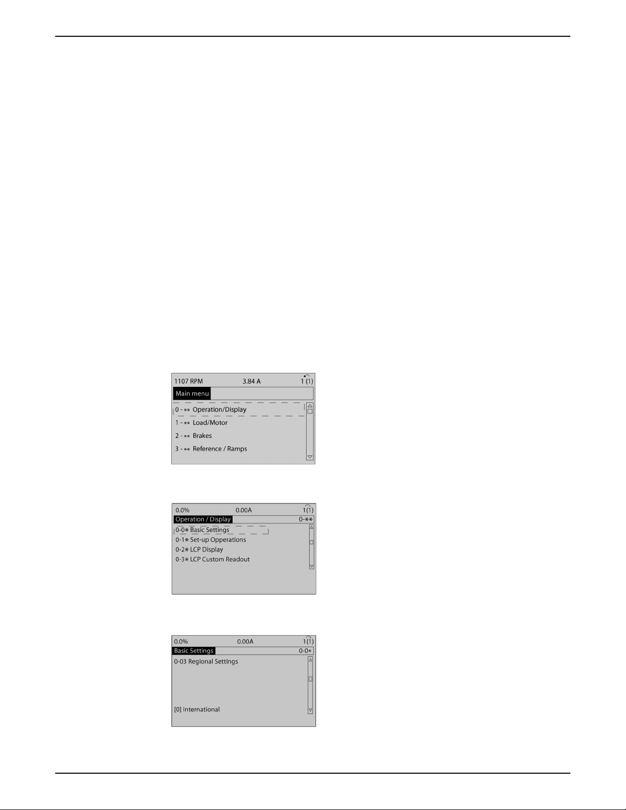
Operation
the up and down arrows to select parameter 0-70 Date and Time. Press [OK] to enabling
editing of the Date and Time parameter. First set the time. Use the up and down arrows to
set the minutes. Then use the left arrow key to scroll left to the hours. Use the up and
down arrows to set the hour of the day. To change to PM, press the up arrow key until the
desired hours and the letter P (found between the minutes and day of the week) are
shown on the display. Next, scroll to the left to set the date. The day of the week on the
right side will update according to the date selected. Press [OK] to save the changes.
NOTE: If the power to the unit is lost, the date and time will reset to factory defaults.
Battery backup for real time clock is available on the Analog I/O Option Card (Input/
Output Option "A" or Repair part number 9K653).
Basic operational programming
Required initial frequency converter programming
NOTE: If the Start-Up Genie is run, ignore the following.
Frequency converters require basic operational programming before running for best
performance. Basic operational programming requires entering motor-nameplate data
for the motor being operated and the minimum and maximum motor speeds. Enter data
in accordance with the following procedure. Parameter settings recommended are
intended for start up and checkout purposes. Application settings may vary. See the Local
Control Panel section for detailed instructions on entering data through the LCP.
Enter data with power ON, but before operating the frequency converter.
1. Press [Main Menu] twice on the LCP.
2. Use the navigation keys to scroll to parameter group 0–** Operation/Display and
press [OK].
Figure 34: Main menu
3. Use navigation keys to scroll to parameter group 0–0* Basic settings and press [OK].
Figure 35: Operation/display
4. Use navigation keys to scroll to 0–3 Regional Settings and press [OK].
Figure 36: Basic settings
94 Aquavar® Intelligent Pump Controller INSTRUCTION MANUAL
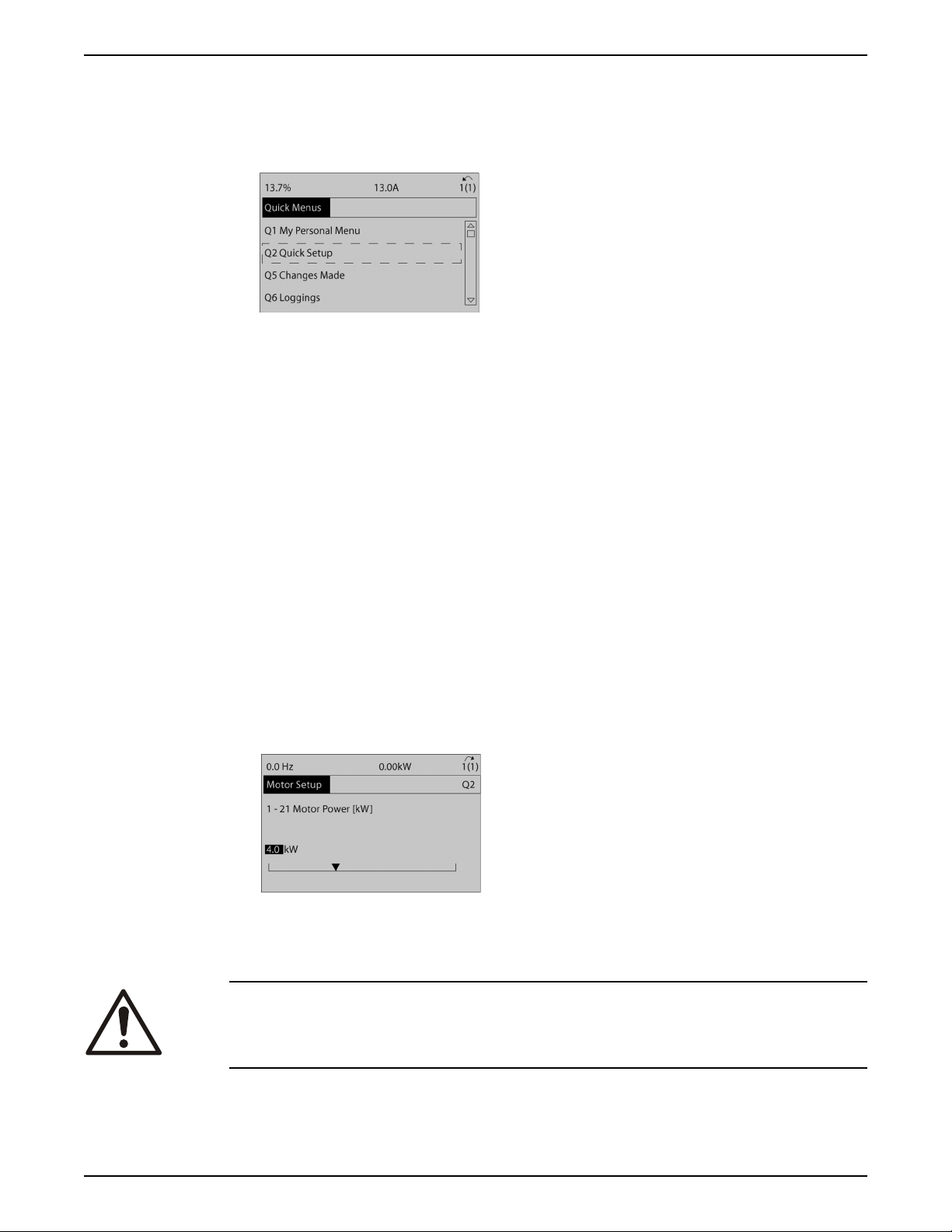
Operation
5. Use navigation keys to select [0] International or [1] North America as appropriate and
press [OK]. This changes the default settings for a number of basic parameters. See
5.4 International/North American Default Parameter Settings for a complete list.)
6. Press [Quick Menu] on the LCP.
7. Use the navigation keys to scroll to parameter group Q2 Quick Setup and press [OK].
Figure 37: Quick menus
8. Select language and press [OK].
9. A jumper wire should be in place between control terminals 12 and 27. If this is the
case, leave 5–12 Terminal 27 Digital Input at factory default. Otherwise select No
Operation. For frequency converters with an optional Xylem bypass, no jumper wire is
required.
10. 3–02 Minimum Reference
11. 3–03 Maximum Reference
12. 3–41 Ramp 1 Ramp Up Time
13. 3–42 Ramp 1 Ramp Down Time
14. 3–13 Reference Site. Linked to Hand/Auto* Local
Induction motor setup
Enter the motor data in parameters 1–20/1–21 to 1–25. The information can be found on
the motor nameplate.
1. • 1–20 Motor Power [kW] or 1–21 Motor Power [HP]
• 1–22 Motor Voltage
• 1–23 Motor Frequency
• 1–24 Motor Current
• 1–25 Motor Nominal Speed
Figure 38: Motor setup
PM motor setup
CAUTION:
Only use PM motor with fans and pumps.
Aquavar® Intelligent Pump Controller INSTRUCTION MANUAL 95

Operation
WARNING:
WINDMILLING! Unintended rotation of permanent magnet motors causes a risk of
personal injuty and equipment damage. Ensure permanent magnet motors are blocked
to prevent unintended rotation.
Initial programming steps
1. Activate PM motor operation 1–10 Motor Construction, select [1] PM, non salient SPM
2. Make sure to set 0–02 Motor Speed Unit to [0] RPM
Programming motor data
After selecting PM motor in 1–10 Motor Construction, the PM motor-related parameters in
parameter groups 1–2* Motor Data, 1–3* Adv. Motor Data and 1–4* are active.
The information can be found on the motor nameplate and in the motor data sheet.
The following parameters must be programmed in the listed order:
1. 1–24 Motor Current
2. 1–26 Motor Cont. Rated Torque
3. 1–25 Motor Nominal Speed
4. 1–39 Motor Poles
5. 1–30 Stator Resistance (Rs)
6. 1–37 d-axis Inductance (Ld)
7. 1–40 Back EMF at 1000 RPM
a. Enter line to common stator winding resistance (Rs). If only line-line data are
available, divide the line-line value with 2 to achieve the line to common
(starpoint) value.
b. It is also possible to measure the value with an ohmmeter, which will also take the
resistance of the cable into account. Divide the measured value by 2 and enter the
result.
a. Enter line to common direct axis inductance of the PM motor.
b. If only line-line data are available, divide the line-line value with 2 to achieve the
line-common (starpoint) value.
c. It is also possible to measure the value with an inductance meter, which will also
take the inductance of the cable into account. Divide the measured value by 2 and
enter the result.
a. Enter line to line back EMF of PM Motor at 1000 RPM mechanical speed (RMS
value). Back EMF is the voltage generated by a PM motor when no drive is
connected and the shaft is turned externally. Back EMF is normally specified for
nominal motor speed or for 1000 RPM measured between two lines. If the value is
not available for a motor speed of 1000 RPM, calculate the correct value as
follows: If back EMF is e.g. 320 V at 1800 RPM, it can be calculated at 1000 RPM as
follows: Back EMF = (Voltage / RPM)*1000 = (320/1800)*1000 = 178. This is the
value that must be programmed for 1–40 Back EMF at 1000 RPM.
Test motor operation
1. Start the motor at low speed (100 to 200 RPM). If the motor does not turn, check
installation, general programming and motor data.
2. Check if start function in 1–70 PM Start Mode fits the application requirements.
Rotor detection
This function is the recommended choice for applications where the motor starts from
standstill e.g. pumps or conveyors. On some motors, an acoustic sound is heard when the
impulse is sent out. This does not harm the motor.
Parking
This function is the recommended choice for applications where the motor is rotating at
slow speed eg. windmilling in fan applications. 2–06 Parking Current and 2–07 Parking
96 Aquavar® Intelligent Pump Controller INSTRUCTION MANUAL

Operation
Time can be adjusted. Increase the factory setting of these parameters for applications
with high inertia.
Start the motor at nominal speed. In case the application does not run well, check the
plus
VVC
PM settings.
Recommendations in different applications can be seen in the following table:
Table 25: Recommendations in different applications
Application Settings
Low inertia applications
I
Load/IMotor
<5
• 1–17 Voltage filter time const. to be increased by
factor 5 to 10
• 1–14 Damping Gain should be reduced
• 1–66 Min. Current at Low Speed should be reduced
(<100%)
Low inertia applications
5–>I
Load/IMotor
> 5
High inertia applications
I
Load/IMotor
> 50
High load at low speed
<30% (rated speed)
Keep calculated values
1–14 Damping Gain, 1–15 Low Speed Filter time Const.
and 1–16 High Speed Filter Time Const. should be
increased
1–17 Voltage filter time const. should be increased
1–66 Min. Current at Low Speed should be increased
(>100% for longer time can overheat the motor)
If the motor starts oscillating at a certain speed, increase 1–14 Damping Gain. Increase the
value in small steps.
Depending on the motor, a good value for this parameter can be 10% or 100% higher
than the default value.
Starting torque can be adjusted in 1–66 Min. Current at Low Speed. 100% provides
nominal torque as starting torque.
Check motor rotation
Before running the frequency converter, check the motor rotation. The motor will run
briefly at 5 Hz or the minimum frequency set in 4–12 Motor Speed Low Limit [Hz].
1. Press [Quick Menu].
2. Scroll to Q2 Quick Setup.
3. Press [OK].
4. Scroll to 1–28 Motor Rotation Check.
5. Press [OK].
6. Scroll to [1] Enable.
The following text will appear: NOTE! Motor may run in wrong direction.
7. Press [OK].
8. Follow the on-screen instructions.
To change the direction of rotation, remove power to the frequency converter and wait for
power to discharge. Reverse the connection of any two of the three motor cables on the
motor or frequency converter side of the connection.
Local-control test
CAUTION:
MOTOR START. Ensure that the motor, system and any attached equipment are ready for
start. It is the responsibility of the user to ensure safe operation under any condition.
Aquavar® Intelligent Pump Controller INSTRUCTION MANUAL 97

Operation
NOTE: The [Hand On] key provides a local start command to the frequency converter. The
[Off] key provides the stop function.
When operating in local mode, [▲] and [▼] increase and decrease the speed output of
the frequency converter. [◄] and [►] move the display cursor in the numeric display.
1. Press [Hand On].
2. Accelerate the frequency converter by pressing [▲] to full speed. Moving the cursor
left of the decimal point provides quicker input changes.
3. Note any acceleration problems.
4. Press [Off].
5. Note any deceleration problems.
If acceleration problems were encountered:
• If warnings or alarms occur, see Warnings and Alarms section for details.
• Check that motor data is entered correctly.
• Increase the ramp-up time in 3–41 Ramp 1 Ramp Up Time
• Increase current limit in 4–18 Current Limit
• Increase torque limit in 4–16 Torque Limit Motor Mode
If deceleration problems were encountered:
• If warnings or alarms occur, see Warnings and Alarms section for details.
• Check that motor data is entered correctly.
• Increase the ramp-down time in 3–42 Ramp 1 Ramp Down Time
• Enable overvoltage control in 2–17 Over-voltage Control
See Local Control Panel for details on resetting the frequency converter after a trip.
System start-up
The procedure in this section requires user-wiring and application programming to be
completed. Application set-up examples are intended to help with this task. Other aids to
application set-up are listed in 1.2 Additional Resources. The following procedure is
recommended after application set-up by the user is completed.
NOTICE:
MOTOR START. Ensure that the motor, system and any attached equipment is ready for
start.
1. Press [Auto On].
2. Ensure that external control function are properly wired to the frequency converter
and all programming is completed.
3. Apply an external run command.
4. Adjust the speed reference throughout the speed range.
5. Remove the external run command.
6. Note any problems.
If warning or alarms occur, see Warnings and Alarms section for details on
troubleshooting.
Acoustic noise or vibration
If the motor or the equipment driven by the motor, for example a pump impeller blade, is
making noise or vibrations at certain frequencies, try the following:
• Speed Bypass, parameter group 4–6*
• Over-modulation, 14–03 Overmodulation set to off
• Switching pattern and switching frequency parameter group 14–0*
• Resonance Dampening, 1–64 Resonance Dampening
98 Aquavar® Intelligent Pump Controller INSTRUCTION MANUAL
 Loading...