


Xylem EHR IM User Manual

Installation and Operating Instruc-
tions for Electric heater-circulator
unit EPR
Instruction manual Laing Electric heater circulator unit
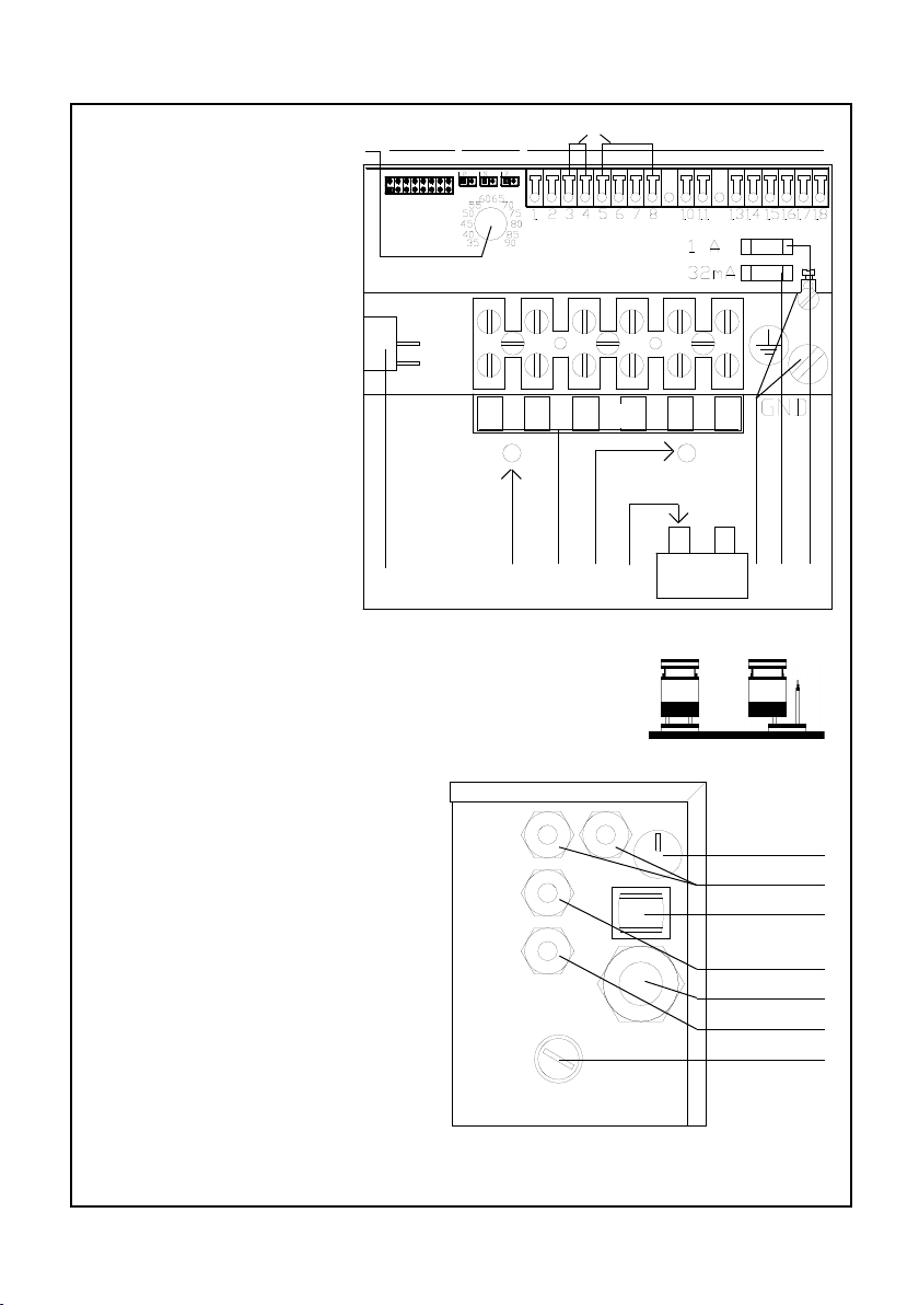
A Terminal strip for Mains
connection
E Ground terminal
F Fuse for pump
H Main switch
I Jumper wires for remote
control input and pump
module input
J Jumper 1 to 8
K Constant temperature
control
L LEDs
M Mounting screws for prin-
ted circuit board (behind
terminal bracket)
N Cable entry for Mains
connection
R Cable entry for control
and circulator
S Safety temperature limiter
U Fuse for control
V Terminals
Z Reset knob for safety
temperature limiter
S J L V
I
L1 L2 L3 N N N
H M A M T E U F
Jumperposition
closed open
Terminal usage
1,2 Remote control for heating
elements 2 and 3
3,4 Input from pump module
5,6 Remote control input
7,8 Remote control input
10,11 Potential free output for remo-
te trouble indicator
13,14 Power supply for daughter
board EPRBW
15,16 Power supply for circulator
17,18 used only for FP 5000 ER
models
See next to last page for jumper positions and error indicators.
2
K
R
H
R
N
R
Z
www.lainginc.com

Instruction manual Laing Electric heater circulator unit
Contents
Applications ............................................................................................................... 5
Design of the EPR model .......................................................................................... 5
Technical Data ........................................................................................................... 6
Dimensional Drawing................................................................................................. 7
Performance Curve ................................................................................................... 7
Models Available ........................................................................................................ 8
Mounting .................................................................................................................... 9
Connection to the feed and return line ...................................................................... 9
Electrical Connection ............................................................................................... 10
Power Supply .......................................................................................................... 10
400V N3 Electrical Diagram .................................................................................... 10
230V N1 Electrical Diagram .....................................................................................
230V N3 Electrical Diagram .....................................................................................
The integrated control.............................................................................................. 12
Schematics of the integrated control ....................................................................... 12
Design of the Main Printed Circuit Board ................................................................ 13
Main switch .............................................................................................................. 14
Fuses ....................................................................................................................... 14
Constant temperature control .................................................................................. 14
Overheating Protection ............................................................................................ 14
Program selection for the switching sequence of the heating elements ................. 15
Pump shut-off ......................................................................................................... 17
Deactivating heating elements ................................................................................ 17
Remote control of the second and third heating element ........................................ 17
Control input ............................................................................................................ 18
Room temperature guided control ........................................................................... 18
Outside temperature guided control ........................................................................ 20
Safety temperature limiter ....................................................................................... 20
Electronic means to prevent dry running ................................................................. 21
Circulator operation control ..................................................................................... 21
Malfunction detector ................................................................................................ 22
Attachment of the sensor for the remote control ..................................................... 23
Indirect domestic hot water heating with the Electric heater-circulator EPR ........... 24
Hydraulic connection of the EPR for domestic hot water heating............................ 25
Electrical connection of the EPR for domestic hot water heating ............................ 26
Control method 1 ..................................................................................................... 26
Control method 2 ..................................................................................................... 27
Operation of heating elements with a load shedding device ................................... 28
Filling of the system ................................................................................................. 30
Pressure and leak tests ........................................................................................... 30
Starting operation .................................................................................................... 30
Replacement of the circulation pump ...................................................................... 31
Replacement of the safety temperature limiter STBR ............................................. 31
Replacement of the main circuit board EPRH ......................................................... 32
Important Notices .................................................................................................... 32
Important Notice: How to avoid overheating............................................................ 32
Important Notice: In the event of safety temperature limiter failure ......................... 33
Important Notice: For proper connection to a oor heating system ......................... 33
Factory settings ....................................................................................................... 33
11
11
www.lainginc.com
3
Instruction manual Laing Electric heater circulator unit
Applications
Electric heater circulator units Model EPR can be applied in all cases where
electric heating has to be installed in a small space to heat an apartment or
a single or multiple family house.
This applies to direct electrical heating as well as for electrical heating with
a heat storage.
A further application exists in connection with room additions where the
electric heating can supplement the existing hydronic heating.
The Electric heater-circulator is also very well suited to heat domestic
hot water. The application for heating of domestic hot water is described in
“Indirect domestic hot water heating - Application”.
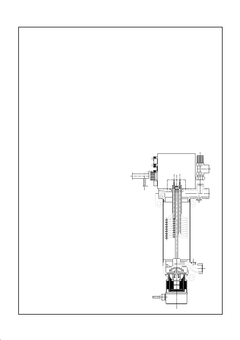
Design of the EPR model
The Electric heater circulator model EPR consists of a circulator pump, an
electric heater with three heating elements and an electronic microprocessor
control.
The spherical motor circulator
operates almost noiselessly and stays
quiet over its lifetime.
The arrangement of the pump below the heating elements guarantees
good heat conductivity from the heating elements since the swirl created
by the impeller extends over the length
of the heating elements. This avoids
overheating of the heating element
surfaces.
The water for the heating loop is drawn
in by the circulator, conveyed along
the heating elements and discharged
through the discharge port at the
upper part of the housing. The inlet
has an additional 3/8” port, to which
an expansion tank can be connected.
An automatic air vent and a pressure
relief valve communicate with the
outlet port.
Mounting eyelets are included in
the castings of the unit.
4
www.lainginc.com

Instruction manual Laing Electric heater circulator unit
The Electric heater circulator units EPR 6 to EPR 15 differ only in the performance of the electrical heating elements and the distance between the ports.
EPR 6 has a heating performance of 6000 W, EPR 9 has 9000 W, EPR 12
has 12000 W and EPR 15 has 15000W.
The control unit, which controls a variety of control and safety functions, is
arranged on top of the Electric heater circulator.
Technical Data
Model EPR EPR EPR EPR
6 9 12 15
Pmax. 87 PSI
Tmax. 194°F
Connection on water side Union 1” male
Weight 21.8 lb 22.5 lb 23.8 lb 24.5 lb
Pump
Max. Head 4.6 PSI
Max. Flow 14.9 GPM
Motor
Design Shaftless spherical motor
Watts Input 99 W
Motor performance 35W
Volts AC 230 V
Amperes 0.43 A
Electric Heater
Electrical performance 6 kW 9 kW 12 kW 15 kW
Number of heating elements 3 3 3 3
Heat capacity per element 2 kW 3 kW 4 kW 5 kW
Voltage 400 V, 3P 400 V, 3P 400 V, 3P 4 0 0 V,
3P
Amperes 8.7 A 13.0 A 17.4 A 21.6 A
Connection Y Y Y Y
Safety Temperature Limiter
Maximum temperature 203°F+/- 5 K
www.lainginc.com
5
Instruction manual Laing Electric heater circulator unit
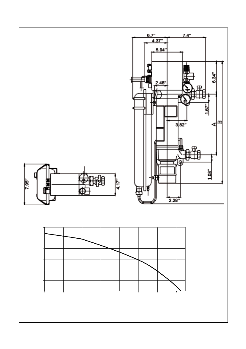
0
2
4
6
8
10
12
0 2 4 6 8 10 12 14
Dimension Drawing
Dimension
Model A B
EPR 6 11.8’’ 23.66’’
EPR 9 11.8’’ 23.66’’
EPR 12 14.37’’ 26.2’’
EPR 15 14.37’’ 26.2’’
Pump curve
Pump head (ft)
6
Flow rate (GPM)
www.lainginc.com
Instruction manual Laing Electric heater circulator unit
Mounting
For safety reasons, the Electric heater circulator must be mounted on a
reproof base. In addition, the unit must be installed with the circulator
motor pointing downwards!
The unit must be attached to a at wall with the help of the mounting eyelets
arranged at the top of the unit and at the pump housing. To avoid noise transfer to the wall, both sides of the mounting eyelets have to be covered with
rubber insulators. The rubber insulators are supplied with the Electric heater
circulator unit and have to be mounted in such a way that no metal contact
exists between the castings and the fastening screw. In addition, no part of
the Electric heater circulator unit - for example the outer shell or the pump
- should be in contact with the wall.
The Electric heater circulator should be mounted at least 2.4’’ above the
oor to allow replacement of the circulator motor if necessary.
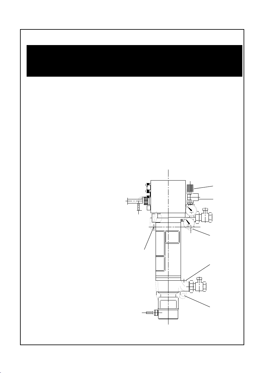
Connection to the feed and return line
The unit is connected to the heating loop by 1” male threaded t-
Air vent
tings. The feed line is at the top of
the unit, the return line at the bottom. The expansion tank should
be connected to the 3/8” port next
to the return line. If the expansion
tank cannot be connected there, it
should be connected somewhere
else in the return line, but not in
the feed line. There are two ˝”
ports at the top of the unit. The
automatic air vent for the heating
circuit is connected to the ˝” port
Mounting
eyelet
Safety relief
valve
Heating
loop feed
side
Mounting
eyelet
Connection
for expansion tank
closest to the wall, the pressure
relief valve to the port in front.
When the Electric heater cir-
Heating
loop return
side
culator unit is used solely for oor
heating, the chapter “Important
Notice: Proper connection to a
Mounting
eyelet
oor heating system” has to be
observed.
Connection EPR series
www.lainginc.com
7
Instruction manual Laing Electric heater circulator unit
Electrical Connection
Notice: The electrical connection has to be performed by a licensed
electrician!
The pump must not be operated without water.
To make the electrical connections, the control box at the top of the heater
has to be opened by removing the 4 screws. A cable with a sufcient cross
section for the performance of the Electric heater circulator unit has to be
inserted through the strain relief and connected to the input terminal (see
Electrical Diagram below)
The circulator is already wired to the control box.
Power Supply
The Electric heater-circulator is designed for three different kinds of power
supply. In all cases the following information has to be taken into account:
The electronic switches integrated into the Electric heater circulator unit do
not separate the heating elements from the power supply. Therefore, a master
switch that interrupts all phases has to be installed in an accessible place,
taking into account all applicable safety codes.
As a protection for the semiconductor relays each phase has to have a fast
acting fuse.
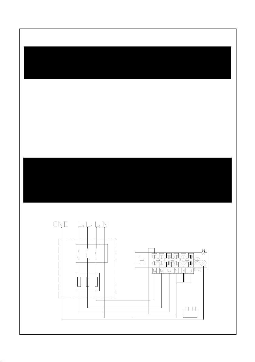
400V N3 Electrical Diagram
230V N1 Electrical Diagram
8
T
www.lainginc.com
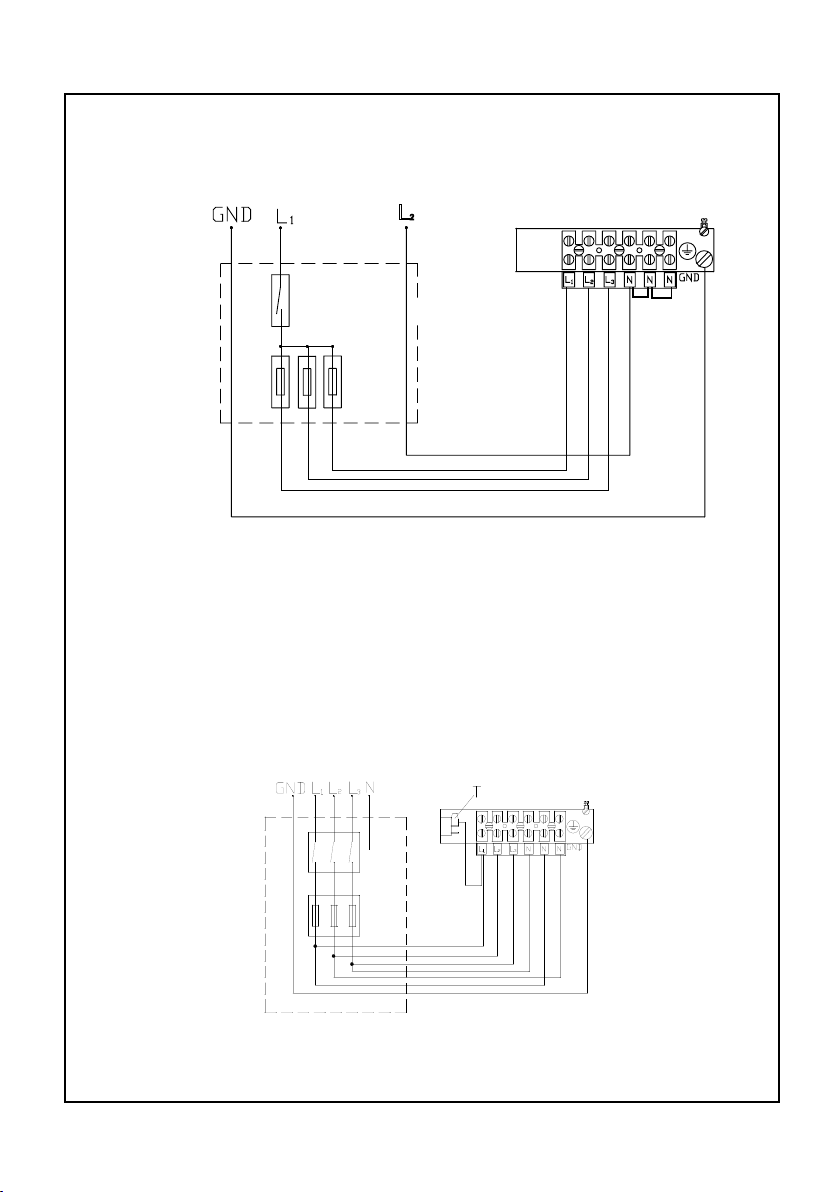
Instruction manual Laing Electric heater circulator unit
L2
In this case, the Electric heater circulator unit has to be connected with 7 leads
to protect each of the semiconductor relays separately. After this has been
done, the leads are combined into one phase.
230V N3 Electrical Diagram
In this case, it is important to ensure the proper phase sequence of the connectors 1 to 3 and 4 to 6.
The integrated control
T
T
www.lainginc.com
9
Instruction manual Laing Electric heater circulator unit
The integrated microprocessor control in the housing on top of the Electric
heater circulator unit performs a variety of control functions for a large number
of applications.
The heating elements are noiselessly switched by electronic relays.
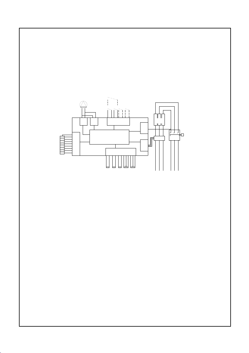
Schematics of the integrated control
The block diagram shows the control in schematic presentation
PI G IS W
TI
Y MP X Q
O
RA
B C D P TS
B Temperature sensor for feed temperature
C Temperature sensor for the safety temperature limiter
D Temperature sensor for the semiconductor relays
G Pump operation control logic
IS Input for external control and remote control
MP Microprocessor
O Control for the semiconductor relays
P Potentiometer for constant temperature setting
PI Pump performance control
Q Safety temperature limiter
RA Analog inputs for temperature sensors and temperature pre-selection
T Potentiometer for safety temperature setting
TI Safety temperature limiter control logic
W Heating elements
X Semiconductor relays
Y Jumper settings for operation mode
Temperature sensor B monitors the temperature of the feed line water and
10
www.lainginc.com
Instruction manual Laing Electric heater circulator unit
passes the information on to the microprocessor. The microprocessor then
activates the solid state relays which in turn activate the heating elements
according to the jumper selected program. An independent sensor C also
monitors the temperature of the feed line water and switches the pump off
when the temperature exceeds a pre-set temperature.
A further sensor D monitors the temperature of the solid state relays and
turns off the heating elements in case of overheating.
A special control logic veries the rotation of the circulator and prevents
the heating elements from being turned on if the circulator is not running.
The safety temperature limiter turns the heating elements off permanently - independent of the electronic control - when the temperature exceeds 194°F.
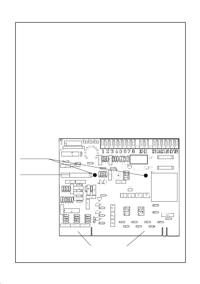
Design of the Main Printed Circuit Board
(See also page 2)
Fastening
points
Processor
Connector for
www.lainginc.com
solid state relays, power supply and sensors.
11
 Loading...