

Model
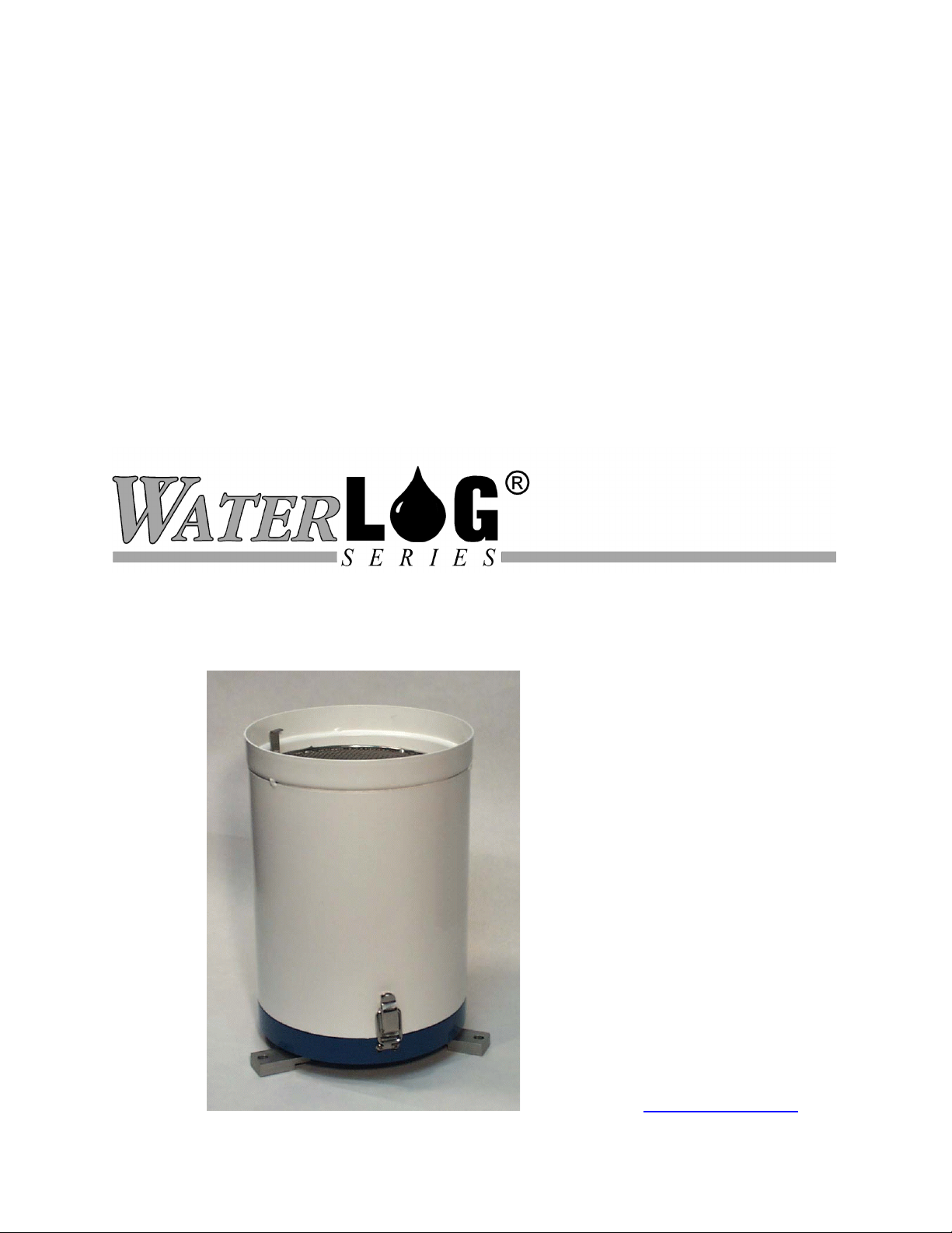
H-340SDI
“Smart” SDI-12 Tipping Bucket
Rain Gauge
Owner's Manual
Version 1.1
Design Analysis Associates
75 West 100 South
Logan, UT 84321 USA
Phone: (435) 753-2212
Fax: (435) 753-7669
Internet: www.waterlog.com
E-mail: sales@waterlog.com


User Agreement/
W
ATER
1. NATURE OF THE PRODUCT
This agreement accompanies a pressure measuring system comprising micro-coded circuitry and
other electronic equipment sealed in an enclosed housing, and packaged together with written
instructional materials. The packaged electronic circuitry and instructional materials herein are
collectively referred to as the “PRODUCT.” The PRODUCT is made available from DESIGN
ANALYSIS ASSOCIATES, INC., of 75 West 100 South, Logan, Utah 84321 (hereinafter
referred to as “DESIGN ANALYSIS”), and contains information and embodies technology that
is confidential and proprietary to DESIGN ANALYSIS, and the availability and use of the
PRODUCT is extended to you, the USER, solely on the basis of the terms of agreement which
follow.
2. ACKNOWLEDGMENTS BY USER
Opening the package which encloses the accompanying PRODUCT indicates your acceptance of
the terms and conditions of this agreement and constitutes an acknowledgment by you of the
confidential and proprietary nature of the rights of DESIGN ANALYSIS in the PRODUCT.
LOG® Warranty
3. DUTIES OF YOU, THE USER
In consideration for the access to and use of the PRODUCT extended to you by DESIGN
ANALYSIS and to protect the confidential and proprietary information of DESIGN ANALYSIS,
USER agrees as follows:
(a) USER agrees that they will not open the sealed housing of the PRODUCT, and that
they will take all necessary precautions to prevent their employees, agents, subcontractors and resellers from doing so.
(b) USER agrees that they will not remove from the exterior of the housing of the
PRODUCT any warnings against opening or notices of proprietary interest placed
thereon by DESIGN ANALYSIS, and that they will take all necessary precautions to
prevent their employees, agents, sub-contractors, and resellers from removing such
markings therefrom.
(c) USER agrees to treat the PRODUCT with the same degree of care as USER
exercises in relation to their own confidential and proprietary information.
(d) USER agrees to return the PRODUCT to DESIGN ANALYSIS if and when the
PRODUCT is deemed to be no longer of use. In return therefore, USER will receive
from DESIGN ANALYSIS a redemption fee of $10.00.
H-340SDI
User Agreement/W
ATER
LOG® Warranty W-1

4. TERM
USER may enjoy these rights only as long as their possession of the PRODUCT shall continue to
be rightful. These rights will cease if the PRODUCT is returned to DESIGN ANALYSIS under
the terms of any redemption offer, warranty, or money-back guarantee, or if USER transfers the
PRODUCT to another party on terms inconsistent with this agreement.
5. LIMITED WARRANTY
(a) What is Covered
DESIGN ANALYSIS warrants that for a period of twelve months from the time of
purchase the functions to be performed by the PRODUCT will be substantially in
compliance with USER documentation. DESIGN ANALYSIS also warrants that the
PRODUCT will be free from defects in materials and workmanship for a period of
ONE YEAR from the date of purchase.
(b) What USER Must Do
If the product fails to satisfy the above warranty, USER must notify DESIGN
ANALYSIS in writing within the applicable period specified above and reasonably
cooperate with the directions they received from DESIGN ANALYSIS.
(c) What DESIGN ANALYSIS Will Do
DESIGN ANALYSIS will repair the PRODUCT or will endeavor to provide a
replacement of same within a reasonable period of time. In the event that DESIGN
ANALYSIS is unable to make the necessary repairs or replacement within a
reasonable period of time, the original purchase price will be refunded upon the
return of the PRODUCT to DESIGN ANALYSIS.
(d) Limitations
(i) THIS LIMITED WARRANTY IS VOIDED WHERE THE SEALED
HOUSING OF THE PRODUCT HAS BEEN OPENED.
(ii) THE ENTIRE REMEDY FOR BREACH OF THIS LIMITED WARRANTY
SHALL BE LIMITED TO REPLACEMENT OF THE DEFECTIVE
PRODUCT OR REFUNDING OF THE PURCHASE PRICE, AS SET
FORTH ABOVE. IN NO EVENT WILL THE LIABILITY OF DESIGN
ANALYSIS TO USER OR TO ANY OTHER PARTY EXCEED THE
ORIGINAL PURCHASE PRICE OF THE PRODUCT, REGARDLESS OF
THE FORM OF THE CLAIM.
W-2 User Agreement/W
ATER
LOG® Warranty
H-340SDI

(iii) EXCEPT FOR THE EXPRESS WARRANTIES ABOVE, DESIGN
ANALYSIS SPECIFICALLY DISCLAIMS ALL OTHER WARRANTIES,
INCLUDING, WITHOUT LIMITATION, ALL IMPLIED WARRANTIES OF
MERCHANTABILITY AND FITNESS FOR A PARTICULAR PURPOSE.
(iv) UNDER NO CIRCUMSTANCES WILL DESIGN ANALYSIS BE LIABLE
FOR SPECIAL, INCIDENTAL, CONSEQUENTIAL, INDIRECT, OR ANY
OTHER DAMAGES OR CLAIMS ARISING FROM THE USE OF THIS
PRODUCT, THIS INCLUDES LOSS OF PROFITS OR ANY OTHER
COMMERCIAL DAMAGES, EVEN IF ADVISED OF THE POSSIBILITY
OF SUCH DAMAGES. IN NO EVENT WILL DESIGN ANALYSIS BE
LIABLE FOR ANY CLAIMS, LIABILITY, OR DAMAGES ARISING
FROM MODIFICATION MADE THEREIN, OTHER THAN BY DESIGN
ANALYSIS.
(v) Should the exclusive remedy stated in subparagraph 6 (d) (ii) above be
determined by a proper court of law to have failed of its essential purpose, the
limitation of the obligations of DESIGN ANALYSIS stated in subparagraphs 6
(d) (iii) and (iv) shall remain valid.
(vi) THIS LIMITED WARRANTY GIVES USER SPECIFIC LEGAL RIGHTS.
USER MAY ALSO HAVE OTHER RIGHTS WHICH VARY FROM STATE
TO STATE. SOME STATES DO NOT ALLOW LIMITATIONS ON HOW
LONG AN IMPLIED WARRANTY LASTS OR THE EXCLUSION OF
INCIDENTAL OR CONSEQUENTIAL DAMAGES, SO THOSE
LIMITATIONS OR EXCLUSIONS MAY NOT APPLY.
6. BINDING AGREEMENT
This is a binding agreement, and if not understood, USER should seek competent legal advice.
By paying for the PRODUCT and opening the package, USER acknowledges to have read this
Agreement and have agreed to be bound by its terms and conditions.
7. GOVERNING LAW
This Agreement and its validity and interpretation shall be governed by the laws of the State of
Utah, notwithstanding any choice of law rules of Utah or any other state or jurisdiction.
8. U.S. GOVERNMENT RESTRICTED RIGHTS
Use, duplication, or disclosure by the United States Government is subject to restrictions set forth
in paragraph (c) (1) (ii) of the rights in Technical Data and Computer Software clause at 52.227-
7013. The Contractor-manufacturer is DESIGN ANALYSIS ASSOCIATES, INC., 75 West
100 South, Logan, Utah 84321.
H-340SDI
User Agreement/W
ATER
LOG® Warranty W-3


1.1 Introduction
Chapter 1
H-340SDI Operation
The
W
ATER
The SDI-12 feature converts a standard tipping bucket rain gauge into a “smart” SDI-12 sensor
with additional capabilities. The H-340SDI is easy to use and works with any data
recorder/logger with a SDI-12 interface. The “Serial-Digital Interface” is ideal for data logging
applications with the following requirements:
Battery powered operation with minimal current drain
Low system cost
Up to 200 feet of cable between a sensor and the data recorder
The H-340SDI has the following features:
Connects directly to any data recorder with a SDI-12 port.
Scales the bucket tips into units of inches, meters etc
Provides built-in accumulation of daily and total rainfall
Provides mathematical correction for bucket volume errors due to varying rainfall rate.
1.2 Theory of Operation
The H-340SDI has a built-in microprocessor which monitors the tipping bucket sensor.
Whenever a bucket tip occurs the microprocessor wakes up from its low power sleep mode and
adds an appropriate rainfall increment to the rainfall accumulators. The electronics has a filter
circuit which prevents contact bounce in the bucket tip reed switch from causing false counts. In
addition, the time between bucket tips is measured, bucket tips which occur less than 500mS
apart are ignored. This helps protect from false counts of a poorly adjusted bucket mechanism.
LOG
®
H-340SDI is a Tipping Bucket Rain Gauge with built-in SDI-12 electronics.
The H-340SDI protects its rainfall accumulations with a software flag or “signature.” If the
power is interrupted momentarily the H-340SDI will resume operation using the accumulation
values in memory. If the power is lost long enough to destroy the signature, when the power is
restored the H-340SDI resets the rainfall accumulators to 0000. To intentionally reset the
H-340SDI's accumulators, disconnect the power for 5 to 10 seconds or use the extended “aXRA”
command.
The H-340SDI provides daily rainfall accumulation values which are useful for data loggers
which do not have special provisions for computing daily rainfall. The H-340SDI has a built-in
real-time-clock which triggers a “daily reset time” event. When this event occurs the H-340SDI
automatically updates its “yesterday’s total accumulation” value using “today’s total
accumulation”, then zeros the “today’s total accumulation” value.
H-340SDI
H-340SDI Operation 1-1

During normal operation, the data recorder sends an address together with a command to the
H-340SDI sensor. The H-340SDI wakes up from its low power sleep mode and stores the
requested data in its data buffer. Once the data is ready, the data recorder collects the data from
the H-340SDI's data buffer.
1.3 “Smart Bucket” Theory
Tipping bucket rain gauges have a reputation for being inaccurate. Inaccuracies can be caused by
algae in the bucket, evaporation and poor calibration. The greatest source of inaccuracy however,
is the volume at which the tipping bucket mechanism tips is sensitive to rainfall rate. This occurs
because the water droplets cause surface waves in the bucket and high rainfall rates cause
superposition or “pile up” of extra water in the bucket before it actually tips over. The following
graph shows the relationship between bucket volume and rainfall rate of a typical tipping bucket.
In this example the bucket volume/tip changes from .009 in/tip to .013 in/tip (a 70% change) as
the rainfall changes from 0 to 25 in/hour. To overcome this problem the microprocessor in the
H-340SDI uses an electronic timer to precisely measure the time between bucket tips. This time
value corresponds to the current rainfall rate. On a bucket-by-bucket basis the microprocessor
uses a built-in polynomial to correct for the intensity sensitivity of the bucket mechanism. For
example, bucket tips which are 50 seconds apart (1 in/hr) are computed with a 0.09in/tip
accumulation. Bucket tips 2 seconds apart (25 in/hr) produce a .012in/tip accumulation.
1-2 H-340SDI Introduction
Figure 1 Bucket tip mechanism sensitivity
H-340SDI
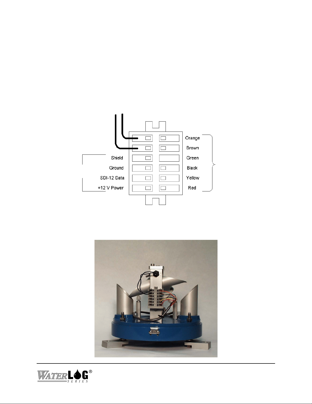
1.4 Making Connections to the H-340SDI
The H-340 has a 6-pin “WAGO” wiring terminal block for connecting the data logger and power.
The terminal block has spring clamp terminals which work with both large and small wires and
provide reliable long-term connections. To open the spring clamp to insert or remove a wire,
insert a small flat screwdriver blade in the square opening adjacent to the wire and twist or pry
carefully to one side.
To Bucket Switch
Internal Cable
SDI Connections
Words of Caution
Keep the lead wires as short as possible.
Use shielded cables in noisy environments.
H-340SDI
H-340SDI Introduction 1-3

1.5 Installation
Install the H-340SDI in an open location where it will not be in the rain shadow of trees or
buildings. A rooftop location helps prevent vandalism and the accumulation of leaves and
debris. Bolt or screw the 3-mounting feet to the structure to prevent upset in high winds. Adjust
the three self-leveling screws until the “bulls eye” level is centered.
1.6 Programming Your Data Recorder
You must prepare your data recorder to receive and record the H-340SDI data. Since data
recorders differ widely, refer to your recorder manufacturer's directions. In general, program the
data recorder to input five values via the SDI-12 port. Usually only one or two of the parameters
is actually recorded. Your data recorder must issue an “aM!” command then collect the data with
a “aD0" command, as explained in Chapter 2. The H-340SDI places five data values in its data
buffer:
+AA.AAA+BBB+CC.CCC+DD.DDD+EE.EEE
Where:
+AA.AAA = Rainfall accumulation since last measurement (inches of rain)
+BB = Number of raw bucket tips since last measurement (counts)
+CC.CCC = Total rainfall accumulation since reset. (inches of rain)
+DD.DDD = Total rainfall accumulation today (inches of rain)
+EE.EEE = Total rainfall accumulation yesterday (inches of rain)
All five of these parameters are automatically reset at power-up, or manually with the extended
SDI-12 “aXRA” Reset Accumulators command.
1.7 Programming the H-340SDI
The H-340SDI comes from the factory with the following settings:
SDI Address: 0
Slope: 1.0
Daily Reset Time: 00:00:00
Time of day: 00:00:00
With these values the data will be in units of inches of rainfall. The setup is stored in EEPROM
within the H-340SDI and will not be lost if the power is disconnected. The extended commands
for changing the slope and sensor address are described in detail in Chapter 2. If more than one
sensor is to be connected to the SDI-12 bus, make certain each sensor has a unique sensor
address.
1-4 H-340SDI Introduction
H-340SDI

In some cases the user may wish to preset the H-340's Total Accumulation value to match the
current rainfall of the water year. The H-340 has an offset value stored in memory which is
automatically added to the Total Accumulation value. The offset value can be written or read
with two extended SDI-12 commands (“aXWO” and “aXRO”), see Chapter 2 for details. Please
note both the Total Accumulation and Offset values are reset at power-up, or with the extended
SDI-12 Reset Accumulators (“aXRA”) command. To change the Total Accumulation to a new
value you must first reset the accumulators with the “aXRA” command, then set the offset with
the “aXWO” command.
1.8 Factory Calibration
The H-340SDI is calibrated in the factory with an apparatus which provides a constant 4in/hour
flow rate. The water exiting from the bottom of the rain gauge is captured in a precision
graduated cylinder. After 100 bucket tips or more have occurred, the flow is stopped and the
volume in the graduated cylinder is measured. The procedure is as follows:
1. Issue an extended “aXRA!” (reset accumulator) SDI-12 command.
2. Empty the graduated cylinder.
3. Start the water flow into the funnel.
4. Wait until at least 100 bucket tips have occurred (1% resolution).
5. Stop the water flow.
6. Observe and record the water volume in the graduated cylinder.
7. Use the formula below to compute the actual rainfall accumulation.
8. Issue a SDI-12 “aM!” measure command and record the “smart bucket” accumulation.
9. Compare the difference between the smart bucket rainfall reading the rainfall volume in the
graduated cylinder.
10. Adjust the counterweight as needed and repeat until the two values are identical or within an
acceptable difference.
The rainfall “volume” equation below converts the volume in the graduated cylinder (mL) into
the equivalent rainfall (in inches) captured by an 8 inch diameter funnel.
in
3
L
NmL x
= ×
121405 10
.
H-340SDI Introduction 1-5
−
3
RAINFALL
NmL
inches inches
=
× ×
mL
1000
in
4 0
( . )
π
61025
.
2
H-340SDI
L

Other related equations of interest:
N
RATE
in
= ×
hr
RAINFALL
RAINFALL
inches
=
tip
inches
min
RAINFALL
N
tips
60
min
hr
inches
1.9 User Calibration
The “smart bucket” processor uses a fixed polynomial to compute each bucket volume as a
function of rainfall rate. The factory calibration should be sufficiently accurate for all rainfall
rates from 0 to 25 inches/hour. If the user requires an exact calibration at a rate other than 4.0
inches/hour, or if the tipping bucket mechanism is damaged or changed the bucket mechanism
may need to be recalibrated. The procedure for adjusting the counterweight is included below.
Please note that the “smart bucket” feature is calibrated somewhat differently than a normal
tipping bucket device. With a simple tippling bucket, a known amount of water is passed
through the gauge and the number of bucket tips is recorded. The counter weight is then adjusted
for the desired number of tips. With the H-340SDI “smart bucket” feature, the number of bucket
tips is not used in the calibration, instead, the SDI-12 measurement value is used. This is
different because the H-340SDI's microprocessor is using a non-linear polynomial expression to
compute the volume. With the aid of the polynomial you can get an accurate field calibration
without using the constant flow apparatus which is used at the factory. Just remember to use the
SDI-12 “aM” measurement values and not the number of bucket tips.
1-6 H-340SDI Introduction
H-340SDI

Lock Nut #1
Counter Weight
Set Screw
Balance Screw
2.062
Bucket Stop
Do Not Adjust
Figure 2
1.10 Adjusting the Tipping Bucket Mechanism
Warning: DO NOT ADJUST THE BUCKET STOPS.
Adjusting the stop posts causes a false reading of equal amounts of water in each bucket. This is
due to the variation of distance the bucket center must travel after passing the bottom of the
funnel. Do not adjust the bucket stops in an attempt to balance the weight of the buckets. Instead,
the H-340SDI provides an adjustable screw parallel to the buckets by which the bucket weight
balance can be accomplished. This eliminates the need to adjust the stops and compensates for
any inequality of weight due to manufacture and assembly, and gives equal travel to each bucket
as the center passes the flow of water.
The counter weight underneath the bucket mechanism can be adjusted (up or down,) to set the
bucket volume (# tips/unit rainfall). See Figure 2. The up/down counter weight adjust
instructions in steps 1 and 2 may seem to be intuitively backwards however, realize the center of
gravity of the bucket and counterweight is above the pivot.
H-340SDI
H-340SDI Introduction 1-7

1. To adjust for more tips (more rainfall volume), release nut #1 and turn weight counter
clockwise (down). Re-lock nut #1.
2. To adjust for less tips (less rainfall volume) release nut #1 and turn weight clockwise (up) .
Re-lock nut #1.
3. To adjust for equal amounts of water in each bucket, loosen set screw #2, turn adjusting
screw toward the bucket with the most amount of water, then re-lock the setscrew.
1-8 H-340SDI Introduction
H-340SDI

SDI-12 Command and Response Protocol
2.1 SDI-12 Command and Response Protocol
Chapter 2
This is a brief description of the Serial Digital Interface (SDI-12) Command and Response protocol
used by the W
and data format supported by the H-340SDI.
Refer to the document "A SERIAL DIGITAL INTERFACE STANDARD FOR HYDROLOGIC
AND ENVIRONMENTAL SENSORS". Version 1.2 April 12, 1996 Coordinated by the SDI-12
Support Group, 135 East Center, Logan, Utah.
During normal communication, the data recorder sends an address together with a command to the
H-340SDI sensor. The H-340SDI then replies with a "response". In the following descriptions,
SDI-12 commands and responses are enclosed in quotes. The SDI-12 address and the
command/response terminators are defined as follows:
ATER
"a" Is the sensor address. The following ASCII Characters are valid addresses:
"!" Is the last character of a command block.
®
LOG
Series Model H-340SDI sensor. Included is a description of the commands
"0-9", "A-Z", "a-z", "*", "?". Sensors will be initially programmed at the
factory with the address of "0" for use in single sensor systems. Addresses
"1 to 9" and "A to Z" or "a to z" can be used for additional sensors connected
to the same SDI-12 bus. Address "*" and "?" are "wild card" addresses which
select any sensor, regardless of its actual address.
Notes:
"<cr><lf>" Are carriage return (0D) hex and line feed (0A) hex characters. They are the
last two characters of a response block.
All commands/responses are upper-case printable ASCII characters.
Commands must be terminated with a "!" character.
Responses are terminated with <cr><lf> characters.
The command string must be transmitted in a contiguous block with no gaps of more than
1.66 milliseconds between characters.
H-340SDI
SDI-12 Command and Response Protocol 2-1

2.2 Measure Command
The Measure Command causes a measurement sequence to be performed. Data values generated
in response to this command are stored in the sensor's buffer for subsequent collection using "D"
commands. The data will be retained in the sensor until another "M", “C” or "V" command is
executed.
Command Response Description
------------------ ---------------------- ------------------------------------
"aM!" "atttn<cr><lf>" Initiate measurement
Where:
a is the sensor address ("0-9", "A-Z", "a-z", "*", "?").
M is an upper-case ASCII character
ttt is a three digit integer (000-999) specifying the maximum time, in seconds,
the sensor will take to complete the command and have measurement data
available in its buffer.
n is a single digit integer (0-9) specifying the number of values that will be
placed in the data buffer. If "n" is zero (0), no data will be available using
subsequent "D" commands.
Upon completion of the measurement, a service request "a<cr><lf>" is sent to the data recorder
indicating the sensor data is ready. The data recorder may wake the sensor with a break and collect
the data anytime after the service request is received or the specified processing time has elapsed.
2-2 SDI-12 Command and Response Protocol
H-340SDI

Example of a H340SDI "aM!" command:
Command Response Time Values Description
------------- --------------------- ------- -------- -------------------------------
"aM!" "a0015<cr><lf>"
Subsequent Command Response
--------------------------- ------------------------------------
"aD0" a+AA.AAA+BB+CC.CCC+DD.DDD+EE.EEE<cr><lf>
Where:
AA.AAA = Rainfall accumulation since last measurement (inches of rain)
BB = Number of bucket tips since last measurement (raw count)
CC.CCC = Total accumulation since reset (inches of rain)
DD.DDD = Total accumulation today (inches of rain)
EE.EEE = Total accumulation yesterday (inches of rain)
2.3 Concurrent Measurement Command
This is a new command for the Version 1.2 SDI-12 Specification. A concurrent measurement is one
which occurs while other SDI-12 sensors on the bus are also taking measurements. This command
is similar to the “aM!” command, however, the nn field has an extra digit and the sensor does not
issue a service request when it has completed the measurement. Communicating with other sensors
will NOT abort a concurrent measurement. Data values generated in response to this command are
stored in the sensor's buffer for subsequent collection using "D" commands. The data will be
retained in the sensor until another "M", “C” or "V" command is executed.
1 sec 5 Return current accumulations
Command Response Description
------------------ ---------------------- ------------------------------------
"aC!" "atttnn<cr><lf>" Initiate measurement
Where:
a is the sensor address ("0-9", "A-Z", "a-z", "*", "?").
C is an upper-case ASCII character
ttt is a three digit integer (000-999) specifying the maximum time, in seconds,
the sensor will take to complete the command and have measurement data
available in its buffer.
nn is a two digit integer (00-99) specifying the number of values that will be
placed in the data buffer. If "n" is zero (0), no data will be available using
subsequent "D" commands.
H-340SDI
SDI-12 Command and Response Protocol 2-3

The data recorder may wake the sensor with a break and collect the data anytime after the specified
processing time has elapsed.
2.4 Send Data Command
The Send Data command returns sensor data generated as the result of previous "aM!", “aC!” or
"aV!" commands. Values returned will be sent in 33 characters or less. The sensor's data buffer will
not be altered by this command.
Command Response
------------- --------------------------------------
"aD0!" through "aD9!" "apd.d ... pd.d<cr><lf>"
Where:
a is the sensor address ("0-9", "A-Z", "a-z", "*", "?").
D0..D9 are upper-case ASCII characters.
p Is a polarity sign (+ or -)
d.d represents numeric digits before and/or after the decimal. A decimal may be
used in any position in the value after the polarity sign. If a decimal is not
used, it will be assumed to be after the last digit.
For example: +3.29 +23.5 -25.45 +300
If one or more values were specified and a "aD0!" returns no data (a<CR><LF> only), it means that
the measurement was aborted and a new "M" command must be sent.
2-4 SDI-12 Command and Response Protocol
H-340SDI

Example of a H-340SDI "aD0!" command:
Previous command Response
----------------------- ------------------------------------------
"aM!" "a0015<cr><lf>"
Subsequent Command Response
--------------------------- ------------------------------------
"aD0" a+AA.AAA+BB+CC.CCC+DD.DDD+EE.EEE<cr><lf>
Where:
AA.AAA = Rainfall accumulation since last measurement (inches of rain)
BB = Number of bucket tips since last measurement (raw count)
CC.CCC = Total accumulation since reset (inches of rain)
DD.DDD = Total accumulation today (inches of rain)
EE.EEE = Total accumulation yesterday (inches of rain)
2.5 Continuous Measurements
This is a new command for the Version 1.2 SDI-12 Specification. Sensors that are able to
continuously monitor the phenomena to be measured, such as a cable, do not require a start
measurement command. They can be read directly with the R commands (R0!...R9!). The R
commands work exactly like the D (D0!...D9!) commands. The only difference is that the R
commands do not need to be preceded with an M command.
The H-340SDI DOES NOT supports the aR0! continuous measurement command.
2.6 Initiate Verify Command
The Verify Command causes a verify sequence to be performed. The result of this command is
similar to the "aM!" command except that the values generated are fixed test data and the results of
diagnostic checksum tests. The data generated in response to this command is placed in the sensor's
buffer for subsequent collection using "D" commands. The data will be retained in the sensor until
another “M”, “C” or “V” command is executed.
Command Response Description
------------- ------------------------- ---------------------------
"aV!" "atttn<cr><lf>" Initiate verify sequence
Where:
a is the sensor address ("0-9", "A-Z", "a-z", "*", "?").
H-340SDI
SDI-12 Command and Response Protocol 2-5

V is an upper-case ASCII character.
ttt is a three digit integer (000-999) specifying the maximum time, in seconds,
the sensor will take to complete the command and have data available in its
buffer.
n is a single digit integer (0-9) specifying the number of values that will be
placed in the data buffer. If "n" is zero (0), no data will be available using
subsequent "D" commands
Example of a H-340SDI "aV!" command:
Command Response Time Values Description
------------- --------------------- ------- -------- ---------------------------
"aV!" "a0013<cr><lf>"
Subsequent Command Response
--------------------------- --------------------------------------------
"aD0" a+123.456+78.9+y<cr><lf>
1 sec 3 Return fixed data and diagnostic
data for testing purposes.
Key Description Units
------------- ------------------------- --------------------------- +123.456 Fixed test data
+78.9 Fixed test data
y ROM checksum test 0 = Failed, 1 = Passed
2.7 Send Acknowledge Command
The Send Acknowledge Command returns a simple status response which includes the address of
the sensor. Any measurement data in the sensor's buffer is not disturbed.
Command Response
------------- -------------------------
"a!" "a<cr><lf>"
Where:
a Is the sensor address ("0-9", "A-Z", "a-z", "*", "?").
2-6 SDI-12 Command and Response Protocol
H-340SDI

2.8 Send Identification Command
The Send Identification command responds with sensor vendor, model, and version data. Any
measurement data in the sensor's buffer is not disturbed.
Command Response
------------- ------------------------------------------------------------
"aI!" "allccccccccmmmmmmvvvxx...xx<cr><lf>"
Where:
a is the sensor address ("0-9", "A-Z", "a-z", "*", "?").
I is an upper-case ASCII character.
ll is the SDI-12 version compatibility level, e.g. version 1.2 is represented as
"12".
cccccccc is an 8 character vendor identification to be specified by the vendor and
usually in the form of a company name or its abbreviation.
mmmmmm is a 6 character field specifying the sensor model number.
vvv is a 3 character field specifying the sensor version number.
xx...xx is an optional field of up to a maximum of 13 characters to be used for serial
number or other specific sensor information not relevant to operation of the
data recorder.
Example of a H-340SDI "aI!" command:
"a12 DAA H-340vvvS#nnnnnnVkkk<cr><lf>"
H-340 implementation of the optional 13 character field:
S#nnnnnnVkkk
Where:
"nnnnnn" is a six character sensor serial number
"kkk" is a three digit sensor firmware revision level
(12 bytes total)
H-340SDI
SDI-12 Command and Response Protocol 2-7

2.9 Change Sensor Address
The Change Sensor Address Command allows the sensor address to be changed. The address is
stored in non-volatile EEPROM within the sensor. The H-340SDI will not respond if the command
was invalid, the address was out of range, or the EEPROM programming operation failed.
Command Response Description
------------- ------------------------- ---------------------------
"aAn!" "n<cr><lf>" Change sensor address
Where:
a is the current (old) sensor address ("0-9", "A-Z", "a-z", "*", "?"). An ASCII
"*" may be used as a "wild card" address if the current address is unknown
and only one sensor is connected to the bus.
A is an upper-case ASCII character.
n is the new sensor address to be programmed ("0-9", "A-Z", "a-z", "*", "?").
NOTE: To verify the new address use the "Identify Command."
Example of a "Change Sensor Address" command:
Command Response Description
------------- ------------------------ ----------------------------
"aA2!" "2<cr><lf>"
2.10 Extend “Read Slope” Command
The H-340SDI processes the rainfall accumulation values with a “mX” equation. The slope (m) term
is programmable, allowing the user to scale the rainfall value into other engineering units. This
command allows the user to read the current slope term. At the factory the slope is set to 1.000
which provides output data in “inches” of rainfall.
Command Response Description
------------- ------------------------- -----------------------------
"aXRS!" "a0011<cr><lf>"
Where:
a is the sensor address ("0-9", "A-Z", "a-z", "*", "?").
Change sensor address to "2"
Read Slope
XRS are upper case characters
2-8 SDI-12 Command and Response Protocol
H-340SDI

This command takes 001 seconds to complete and places 1 value in the data buffer. Use the “aD0"
command to collect and view the data.
Example of a H-340SDI Extended "Read Slope" command:
Command Response Time Values Description
------------------- ------------------------ ------ --------- -----------------------------
"XRS!" "a0011<cr><lf>"
Subsequent Command Response
--------------------------- ------------------------------------
"aD0" a+1.000<cr><lf>
2.11 Extended “Write Slope” Command
The H-340SDI processes the raw rainfall values with a “mX” equation. The slope (m) term is
programmable, allowing the user to scale the rain fall value into other engineering units. This
command allows the user to write (change) the current slope term. At the factory the slope is set to
1.000 which provides output data in “inches” of rainfall. The new value is stored in non-volatile
EEPROM within the sensor. Once the new slope value is written to the EEPROM, a copy is sent
to the sensor data buffer for verification. This data can be viewed by using a subsequent "D"
command. To verify the Slope any other time, use the "Read Slope" command.
1 sec 1 Read Slope
Command Response Description
------------- ------------------------- -----------------------------
"aXWSddd!" "a0011<cr><lf>"
Where:
a is the sensor address ("0-9", "A-Z", "a-z", "*", "?").
XWS are upper case characters.
ddd is the new slope value. The input format is
very flexible. Some examples are shown below.
20.0
0.195
-500
5.93E-4
H-340SDI
SDI-12 Command and Response Protocol 2-9
Write Slope

This command takes 001 seconds to complete and places 1 value in the data buffer. Use the “aD0"
command to collect and view the data.
Example of a H340SDI extended "Write Slope" command:
Command Response Tim Values Description
------------- --------------------- ------- -------- -------------------------------
"aXWS1.234!" "a0011<cr><lf>"
Subsequent Command Response
--------------------------- ------------------------------------
"aD0" a+123.4<cr><lf>
2.12 Extend “Read Offset” Command
The H-340SDI maintains an offset value in RAM which is automatically added to the Total
Accumulation value. The offset value can be used to match the H340's Total Accumulation to the
current water year rainfall. This command allows the user to read the current offset value. The
offset is automatically set to zero at power-up or with the “aXRA” command.
1 sec 1 Set slope to 1.234
Command Response Description
------------- ------------------------- -----------------------------
"aXR0!" "a0011<cr><lf>"
Where:
a is the sensor address ("0-9", "A-Z", "a-z", "*", "?").
XRO are upper case characters
This command takes 001 seconds to complete and places 1 value in the data buffer. Use the “aD0"
command to collect and view the data.
Read Offset
2-10 SDI-12 Command and Response Protocol
H-340SDI

Example of a H-340SDI Extended "Read Offset" command:
Command Response Time Values Description
------------------- ------------------------ ------ --------- -----------------------------
"XRO!" "a0011<cr><lf>"
Subsequent Command Response
--------------------------- ------------------------------------
"aD0" a+0.000<cr><lf>
2.13 Extended “Write Offset” Command
The H-340SDI maintains an offset value in RAM which is automatically added to the Total
Accumulation value. The offset value can be used to match the H340's Total Accumulation to the
current water year rainfall. This command allows the user to write (change) the current offset. The
offset is automatically set to zero at power-up or with the “aXRA” command. To change the Total
Accumulation to a new value you must first reset the accumulators with the “aXRA” command,
then set the offset with the “aXWO” command.
1 sec 1 Read Offset
The new value is stored in RAM within the sensor and is not preserved if the power is lost. Once
the new offset value is written to the RAM, a copy is sent to the sensor data buffer for verification.
This data can be viewed by using a subsequent "D" command. To verify the Offset any other time,
use the "Read Offset" command.
Command Response Description
------------- ------------------------- -----------------------------
"aXWOddd!" "a0011<cr><lf>"
Where:
a is the sensor address ("0-9", "A-Z", "a-z", "*", "?").
XWO are upper case characters.
ddd is the new offset value. The input format is
very flexible. Some examples are shown below.
20.0
0.195
-500
5.93E-4
Write Offset
H-340SDI
SDI-12 Command and Response Protocol 2-11

This command takes 001 seconds to complete and places 1 value in the data buffer. Use the “aD0"
command to collect and view the data.
Example of a H340SDI extended "Write Offset" command:
Command Response Tim Values Description
------------- --------------------- ------- -------- -------------------------------
"aXWO1.234!" "a0011<cr><lf>"
Subsequent Command Response
--------------------------- ------------------------------------
"aD0" a+123.4<cr><lf>
2.14 Extended “Get Time” Command
The H-340SDI has a built-in real time clock. This command allows the user to read the current time
of day.
Command Response Description
------------- ------------------------- -----------------------------
"aXGT!" "a0013<cr><lf>"
1 sec 1 Set offset to 1.234
Read time of day
Where:
a is the sensor address ("0-9", "A-Z", "a-z", "*", "?").
XGT are upper case characters
This command takes 001 seconds to complete and places 3 values in the data buffer. Use the “aD0"
command to collect and view the data.
2-12 SDI-12 Command and Response Protocol
H-340SDI

Example of a H340SDI extended "Get Time" command:
Command Response Time Values Description
------------- --------------------- ------- -------- -------------------------------
"aXGT!" "a0013<cr><lf>"
Subsequent Command Response
--------------------------- ------------------------------------
"aD0" a+HH+MM+SS<cr><lf>
Where:
HH = Hours (24 hour format)
MM = Minutes
SS = Seconds
2.15 Extended “Set Time” Command
The H-340SDI has a built-in real time clock. This command allows the user to change the current
time of day.
1 sec 3 Get current time of day
Command Response Description
------------- ------------------------- -----------------------------
"aXSTHHMMSS!" "a0013<cr><lf>"
Where:
a is the sensor address ("0-9", "A-Z", "a-z", "*", "?").
XST are upper case characters.
HHMMSS is the new time in Hours:Minutes:Seconds (24-Hour format)
This command takes 001 seconds to complete and places 3 values in the data buffer. Use the “aD0"
command to collect and view the data.
Set time of day
H-340SDI
SDI-12 Command and Response Protocol 2-13

Example of a H340SDI extended "Set Time" command:
Command Response Time Values Description
------------- --------------------- ------- -------- -------------------------------
"aXST234537" "a0011<cr><lf>"
Subsequent Command Response
--------------------------- ------------------------------------
"aD0" a+23+45+37<cr><lf>
2.16 Extended “Get Daily Reset Time” Command
The H-340SDI automatically resets the daily accumulations a certain time each day. For example,
one day may be calculated from 6:00 AM of one day to 6:00 AM of the next day. This command
reads the time of day at which the reset is scheduled.
Command Response Description
------------- ------------------------- -----------------------------
"aXGDRT!" "a0013<cr><lf>"
1 sec 1 Set time of day to 23:45:37
Read daily reset time
Where:
a is the sensor address ("0-9", "A-Z", "a-z", "*", "?").
XGDRT are upper case characters
This command takes 001 seconds to complete and places 3 values in the data buffer. Use the “aD0"
command to collect and view the data.
Example of a H340SDI extended "Get Daily Reset Time" command:
Command Response Time Values Description
------------- --------------------- ------- -------- -------------------------------
"aXGDRT!" "a0013<cr><lf>"
Subsequent Command Response
--------------------------- ------------------------------------
"aD0" a+HH+MM+SS<cr><lf>
Where:
HH = Hours (24 hour format)
MM = Minutes
SS = Seconds
1 sec 3 Get daily reset time
2-14 SDI-12 Command and Response Protocol
H-340SDI

2.17 Extended “Set Daily Reset Time” Command
The H-340SDI automatically resets the daily accumulations a certain time each day. For example,
one day may be calculated from 6:00 AM of one day to 6:00 AM of the next day. This command
sets the time of day at which the reset is scheduled.
Command Response Description
------------- ------------------------- -----------------------------
"aXSDRThhmmss!" "a0013<cr><lf>"
Where:
a is the sensor address ("0-9", "A-Z", "a-z", "*", "?").
XSDRT are upper case characters.
hhmmss is the new time in HOURS:MINUTES:SECONDS (24-Hour format).
Use fixed format. For example 010233 for 01:02:33
This command takes 001 seconds to complete and places 3 values in the data buffer. Use the “aD0"
command to collect and view the data.
Set daily reset time
Example of a H340SDI extended "Set Time" command:
Command Response Time Values Description
------------- -------------------- ------- -------- -------------------------------
"aXSDRT230537" "a0013<cr><lf>"
Subsequent Command Response
--------------------------- ------------------------------------
"aD0" a+23+05+37<cr><lf>
2.18 Extended “XTEST” Command
This command is primarily used for production testing and requires the use of a H-419 or SDI-12
verifier and a PC. This command causes the H-340 to transmit unsolicited real-time data for testing
purposes. This is not compliant with the SDI-12 specification and is not used with data loggers.
To activate the test mode, first send the command “aXTEST!”, then enter the verifier’s MONITOR
mode. Whenever a bucket tip occurs, the H-340 now transmits the time between bucket tips and the
adjusted rainfall for the bucket tip. This test mode may be used to help troubleshoot the installation
by providing a continuous readout of bucket tip timing and rainfall. The test mode is exited by
1 sec 3 Set daily reset time to 23:05:37
H-340SDI
SDI-12 Command and Response Protocol 2-15

sending any new command on the SDI-12 bus (a BREAK terminates). It may take a few tries to exit
if the command is sent at the same time data is being sent from the H-340. Removing power from
the H-340SDI also causes it to exit this mode. Note: bucket tips less than 500mS apart are discarded
(ignored) by the H340SDI.
Example of the XTEST test display:
+1.200+.013 (Time between tip is 1.2 Seconds, rainfall for this tip is 0.013 inches)
+60.00+.009
+4.400+.012
+2.2+.011
etc.
2-16 SDI-12 Command and Response Protocol
H-340SDI

Appendix A
Specifications
General
Output: SDI-12
Power Input
Voltage: 9.6 to 16.0 Volts DC
Current:
Standby Mode: 150A
Raining: 3.7 mA for 60 sec
Communicating: 9.8 mA
Timing
SDI-12: 1 second measurement
sequence
SDI-12 Output
Baud Rate: 1200
Protocol: SDI-12, 7-bit even parity,
1 stop bit
Output Voltage Levels:
minimum high level: 3.5 volts
maximum low level: 0.8 volts
maximum cable length: 200 ft.
Environmental (electronics)
Operating Temperature: -40 to 50 C
Storage Temperature: -50 to 70 C
Mechanical
Operating Temperature: -0 to 50 C
Connectors
SDI-12 Output: 4-position spring clamp terminal
block (WAGO).
Mechanical
Bucket Tip
Sensor: Magnetic reed switch.
Aperture: 8" diameter funnel
Housing: 8" diameter extruded aluminum
tube. Cast aluminum base with
drain tubes in the bottom.
Anodized aluminum internal parts.
Stainless steel screws and
fasteners. Powder painted base,
funnel and housing.
Mounting: 3 leveling screws with bolt down
feet.
Weight: 8 pounds
Calibration
Built in processor measures the time between bucket
tips (rainfall rate) and uses this data to compute the
bucket volume per tip at the current rainfall rate. A
built-in polynomial provides corrected bucket volume
for rainfall rates between 0 and 25 in/hour.
Warranty
The W
ATER
LOG® H-340SDI is warranted against
defects in materials and workmanship for one year
from date of shipment.
H-340SDI
Appendix A Specifications A-1

 Loading...