


Gebrauchsanleitung / Operating manual
Labor-pH-Meter
Laboratory pH Meter
CG 842
ba12242de_2 09/99
Bedienungsanleitung Seite 1
Operating manual Page 45

Laboratory pH Meter
CG 842
Operating Manual
ba12242e_2 09/99
45

Accuracy when
going to press
All details contained in this operating manual are valid data
at the time of going to press. However, SCHOTT may add
details for both technical and commercial reasons, or in order to fulfil legal requirements of different countries. This
does not affect the characteristics described.
Warranty
declaration
The designated instrument is covered by a warranty of three
years from the date of purchase.
The instrument warranty extends to manufacturing faults
that are determined within the period of warranty.
The warranty excludes components that are replaced during
maintenance such as batteries, etc.
The warranty claim extends to restoring the instrument to
readiness for use but not, however, to any further claim for
damages. Improper handling or unauthorized opening of the
instrument invalidates any warranty claim.
To ascertain the warranty liability, return the instrument and
proof of purchase together with the date of purchase freight
paid or prepaid.
Copyright
© Hofheim SCHOTT Geräte GmbH 1999
Reprinting - even as excerpts - is only allowed with the
explicit written authorization of SCHOTT Geräte GmbH,
Hofheim.
Printed in Germany.

List of contents
1 Overview . . . . . . . . . . . . . . . . . . . . . . . . . . . . . . 49
1.1 Keyboard . . . . . . . . . . . . . . . . . . . . . . . . . . . . . . . . .50
1.2 Display . . . . . . . . . . . . . . . . . . . . . . . . . . . . . . . . . . . 51
1.3 Sockets . . . . . . . . . . . . . . . . . . . . . . . . . . . . . . . . . . 51
1.4 Declaration of conformity . . . . . . . . . . . . . . . . . . . . .52
1.5 Technical data . . . . . . . . . . . . . . . . . . . . . . . . . . . . .53
2 Safety . . . . . . . . . . . . . . . . . . . . . . . . . . . . . . . . 57
2.1 Authorized use . . . . . . . . . . . . . . . . . . . . . . . . . . . .58
2.2 General safety instructions . . . . . . . . . . . . . . . . . . .58
3 Commissioning . . . . . . . . . . . . . . . . . . . . . . . . 61
4 Operation . . . . . . . . . . . . . . . . . . . . . . . . . . . . . 63
4.1 Switch on the instrument . . . . . . . . . . . . . . . . . . . . .63
4.2 Measuring . . . . . . . . . . . . . . . . . . . . . . . . . . . . . . . . 64
4.2.1 Measuring the pH value . . . . . . . . . . . . . . . .6 5
4.2.2 Measuring the Redox voltage . . . . . . . . . . .66
4.3 Calibrating . . . . . . . . . . . . . . . . . . . . . . . . . . . . . . . .67
4.3.1 AutoCal TEC . . . . . . . . . . . . . . . . . . . . . . . . 69
4.3.2 AutoCal DIN . . . . . . . . . . . . . . . . . . . . . . . . .71
4.3.3 ConCal . . . . . . . . . . . . . . . . . . . . . . . . . . . . . 73
4.4 Reset . . . . . . . . . . . . . . . . . . . . . . . . . . . . . . . . . . . .76
5 Maintenance, cleaning, disposal . . . . . . . . . . 77
5.1 Maintenance . . . . . . . . . . . . . . . . . . . . . . . . . . . . . .77
5.2 Cleaning . . . . . . . . . . . . . . . . . . . . . . . . . . . . . . . . .78
5.3 Disposal . . . . . . . . . . . . . . . . . . . . . . . . . . . . . . . . . . 78
6 What to do if... . . . . . . . . . . . . . . . . . . . . . . . . . 79
7 Lists . . . . . . . . . . . . . . . . . . . . . . . . . . . . . . . . . . 83
47

List of contents
48
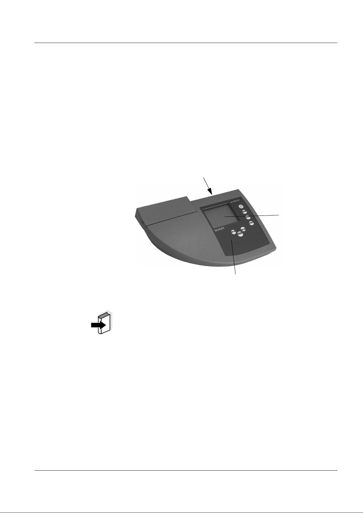
1Overview
Overview
The compact
pH measurements rapidly and reliably.
The
CG 842
fort, reliability and measuring safety for all applications.
The proven calibration procedures and special
function support your work with the pH meter.
CG 842
provides the highest degree of operating com-
precision pH meter lets you perform
AutoRead
3
2
1 Keypad
2 Display
3 Sockets
1
Note
The measuring instrument can also be delivered as part of
a set.
Information on this and other accessories is available in the
SCHOTT general catalog.
49

Overview
1.1 Keyboard
Switch measuring instrument ON/OFF
<on/off>
Select measuring mode
<pH>
Call up calibration procedure
<CAL>
Activate/deactivate AutoRead
<auto read>
Reduce values, scroll
t>
<
Confirm inputs, start AutoRead
<run/enter>
Increase values, scroll
s>
<
50

1.2 Display
1.3 Sockets
Overview
Status line
Measured value display
Function and
temperature displ a y
1 2 3 4
1 Socket according to DIN 19262/BNC
2 Pt1000/NTC30 connector
for pH combined electrodes with
temperature probe
3 Reference electrode connector
4 Connector for
plug-in power supply (optional)
Caution
Only connect probes to the instrument that cannot feed excessive voltages or currents (> SELV and > circuit with current limiter).
Almost all commercial electrodes - especially SCHOTT
electrodes - meet these requirements.
51

Overview
1.4 Declaration of conformity
29.03.99
SCHOTT Geräte GmbH
Im Langgewann 5
D 65719 Hofheim am Taunus
Deutschland, Germany, Allemagne
29. März, March 29rd, 29, Mars, 1999
AGQSF0000-A056-00/990329
52

Ambient
temperature
Overview
1.5 Technical data
Storage temperature - 25 °C ... + 65 °C
Operating temperature 0 °C ... + 55 °C
Measuring ranges
and resolution
Measuring accuracy
(± 1 digit)
Allowable relative humidity
Annual mean: < 75 %
30 days/year: 95 %
Other days: 85 %
pH
(resolution selectable)
- 2.000 ... + 16.000
- 2.00 ... + 16.00
U [mV] - 999.9 ... + 999.9
- 1999 ... + 1999
T [°C] - 5.0 ... + 100.0
T [°F] + 23.0 ... + 212.0
Given as measuring uncertainty at a confidence level of
95%. All accuracies additionally depend on the accuracies
of the measuring probes.
pH
(± 2 pH units around the
± 0.005 at + 15 °C ... + 35 °C
± 0.01
calibration point)
U [mV] ± 0.4 at + 15 °C ... + 35 °C
± 1
T [°C] NTC 30: ± 0.1
PT 1000:
± 0.5 at 0 °C ... 15 °C
± 0.1 at 15 °C ... 35 °C
± 1 at 35 °C ... 55 °C
T [°F] NTC 30: ± 0.2
PT 1000:
± 0.9 at 32 °F ... 59 °F
± 0.2 at 59 °F ... 95 °F
± 1.8 at 95 °F ... 131 °F
53

Overview
Housing
EMC and
VDE norms
Length [mm] 230
Width [mm] 210
Height [mm] 70
Weight [kg] Approx. 0.850
Material ABS
Interference emission
(generic standard)
EN 50081-1
FCC class A
Test marks
Display
Temperature com-
pensation
Keypad Foil keypad (Polyester)
Interference immunity
EN 50082-1
(generic standard)
Protective class 3, EN61010-1
Climatic class 2, VDI/VDE 3540
TÜV GS, UL/CUL, CE
1
Multifunctional LCD
Automatically with Pt
1000/NTC (30 k
W)
-5 ... 99.9 °C
Manual input -20 ... 130 °C resolution 1K
54

Overview
Energy supply
Batteries 4 x 1.5 V AA type alkaline manga-
nese batteries
Runtime Approx. 3000 operating hours
Mains power supply
(option)
Connection max. overvoltage cate-
gory II (valid for all plug-in power
supply units):
Plug-in power supply (Euro plug):
Type no.: Z851
Order no.: 28 520 4897
FRIWO FW3288, 11.8134
Friwo Part No. 1816492
Input: 230V ~ / 50 Hz / 23 VA
Output: 6 V = / 1,8 A /10,8 VA
Plug-in power supply (US plug):
Type no.: Z852
Order no.: 28 520 4901
FRIWO FW3288, 11.8451
Friwo Part No. 1816493
Input: 120V ~ / 60 Hz / 21,5 VA
Output: 6 V = / 1,8 A
Plug-in power supply (UK plug):
Type no.: Z849
Order no.: 28 520 4975
FRIWO FW3288, 11.8453
Friwo Part No. 1770896
Input: 230V ~ / 50 Hz / 23 VA
Output: 6 V = / 1,8 A
55

Overview
Connections
Input amplifier
Calibration modes
Electrodes Socket according to DIN 19 262
or BNC
4 mm socket for reference elec-
trode
Temperature probe 4 mm socket for
temperature probe
Plug-in power supply
2-pole special Friwo
unit
12
10
-12
Ω
A
Input impedance ≥ 10
Offset current ≤
AutoCal TEC With Technical buffers
(given in pH):
2.00; 4.00; 7.00; 10.00 at 25 °C;
buffers are temperature com-
pensated in the range 0 ... 90 °C
AutoCal DIN With standard buffers according
to DIN 19 266/NIST (given in
pH):
1.68; 4.01; 6.87; 9.18 at 25 °C;
buffers are temperature com-
pensated in the range 0 ... 90 °C
ConCal With any buffers;
single-point and two-point cali-
bration,
manual acceptance of measured
values and temperature input
56

Safety
2 Safety
This operating manual contains basic instructions that you
must follow during the commissioning, operation and maintenance of the pH meter. Consequently, all responsible personnel must read this operating manual before working with
the instrument.
The operating manual must always be available within the
vicinity of the instrument.
Target group This measuring instrument was developed for use in the lab-
oratory.
Thus, we assume that, as a result of their professional training and experience, the operators will know the necessary
safety precautions to take when handling chemicals.
Symbols used
Caution
indicates instructions that have to be followed to prevent
damage to your instrument.
Warning
indicates instructions that have to be followed to protect
yourself and the instrument from dangerous electrical voltage.
Note
Indicates notes that draw your attention to special features.
Note
Indicates cross-references to other documents, e.g. application reports, operating manuals of combination electrodes, etc.
57

Safety
2.1 Authorized use
This instrument is authorized exclusively for pH and Redox
measurements in the laboratory.
The technical specifications as given in the chapter, T
CAL DATA, must be observed. Only the operation and run-
ECHNI-
ning of the measuring instrument according to the
instructions given in this operating manual is authorized.
Any other use is considered unauthorized.
2.2 General safety instructions
This instrument is constructed and tested in compliance with
the EN 61010-1 safety regulations for electronic measuring
instruments.
It left the factory in a safe and secure technical condition.
Function and opera-
tional safety
The smooth functioning and operational safety of the instrument can only be guaranteed if the generally applicable
safety measures and the specific safety instructions in this
operating manual are followed.
The smooth functioning and operational safety of the instrument can only be guaranteed under the climatic conditions
specified in the chapter 1.5 T
ECHNICAL DATA.
If the instrument was transported from a cold environment to
a warm environment, the formation of condensate can lead
to the faulty functioning of the instrument. In this event, wait
until the temperature of the instrument reaches room temperature before putting the instrument back into operation.
Caution
The instrument is only allowed to be opened by personnel
authorized by SCHOTT.
58

Safety
Safe operation If safe operation is no longer possible, the instrument must
be taken out of service and secured against inadvertent operation.
Safe operation is no longer possible if:
l the instrument has been damaged in transport
l the instrument has been stored under adverse conditions
for a lengthy period of time
l the instrument is visibly damaged
l the instrument no longer operates as described in this
manual
If you are in doubt contact the supplier of the instrument.
Obligations of the
operator
The operator of this measuring instrument must ensure that
the following laws and guidelines are observed when using
dangerous substances:
l EEC directives for protective labor legislation
l National protective labor legislation
l Safety regulations
l Safety datasheets of the chemical manufacturer.
59

Safety
60

Commissioning
3 Commissioning
Perform the following activities for the initial commissioning:
l Set the °C or °F
l Set the resolution
l Connect the plug-in power supply (optional).
Setting °C or °F The temperature can be displayed in °C or in °F . In the de-
livery condition, the measuring instrument is preset to °C.
To change the unit proceed as follows:
1 Switch the measuring instrument off.
2 Press and hold down the <pH> key.
Setting the
resolution
3 Press the <on/off> key.
4 Toggle between °C and °F by pressing <▲> <▼>.
5 Confirm with <run/enter>.
The measuring instrument switches to the measuring
mode.
1 Press and hold down the <run/enter> key.
2 Press the <pH> key. The measured values are dis-
played with a high resolution, e. g. pH = 4.012.
61

Commissioning
3 Press the <run/enter> and <pH> keys again.
The measured values are displayed with a low resolution, e. g. pH = 4.01.
Connecting the
plug-in power
supply (optional)
The measuring instrument works battery-powered. It can,
however, also be supplied by the plug-in power supply
which is available as an accessory.
Warning
The line voltage on site must lie within the input voltage
range of the original plug-in power supply unit (see section
ECHNICAL DATA).
1.5 T
Caution
Use original plug-in power supplies only
(see section 1.5 T
ECHNICAL DATA).
62
2
1
3
1 Insert the plug (1) into the socket (2) of the pH meter.
2 Connect the original plug-in power supply (3) to an
easily accessible mains socket.

Operation
4Operation
4.1 Switch on the instrument
1 Place the instrument on a flat surface and protect it
against intense light and heat.
2 Press the <on/off> key.
display test
The
The instrument then switches automatically to the
previously selected measuring mode.
3 Connect the pH electrode to the instrument.
The measuring instrument is ready for operation.
appears briefly on the display.
Note
The instrument has an energy saving feature to avoid unnecessary battery depletion.
The energy saving feature switches the instrument off if no
key has been pressed for an hour.
The energy saving feature is not active if the instrument is
supplied by the plug-in power supply.
63

Operation
4.2 Measuring
Preparatory
Perform the following activities when you want to measure:
activities
1 Connect the pH electrode to the instrument.
2 Adjust the temperature of the buffer or test solutions
or measure the current temperature if the measurement is made without a temperature probe.
3 Calibrate or check the instrument with the pH elec-
trode according to section 4.3.
4 Select the measuring mode by pressing <pH>.
Note
Incorrect calibration of the pH electrode will result in incorrect measured values. Therefore, regularly perform calibration before measuring.
Temperature probe Measurements can be performed with and without a temper-
ature probe. A connected temperature probe is indicated by
TP on the display.
Note
The pH meter automatically recognizes the type of the temperature probe used. As a result, you can connect electrodes with the NTC30 or Pt1000.
The temperature measurement is absolutely essential for a
reproducible pH measurement. If the measurement is made
without a temperature probe, proceed as follows:
1 Determine the current temperature using a thermo-
meter.
2 Set up the temperature by pressing <
▲> <▼>.
Note
When calibrating without a temperature probe, set up the
current temperature of the respective buffer solution manually by pressing the <
▲> <▼> keys.
64

Operation
4.2.1 Measuring the pH value
1 Perform the preparatory activities according to sec-
tion 4.2.
2 Immerse the pH electrode into the test sample.
AutoRead AR
(Drift control)
3 Press the <pH> key until
pH
appears in the status
display. The pH value appears on the display.
The
AutoRead
function (drift control) checks the stability of
the measurement signal. The stability has a considerable effect on the reproducibility of the measured values.
For identical measurement conditions, the following criteria
apply:
l pH value: better than 0.02 (setting time: > 30 s)
1 Call up the pH measuring mode by pressing <pH>.
2 Activate the AutoRead function by pressing <auto
read>.
The current measured value is frozen (Hold function).
3 Start the AutoRead function by pressing
<run/enter>.
AR flashes on the display until a stable measured value is reached.
4 If necessary, start the next AutoRead measurement
by pressing <run/enter>.
5 To terminate the AutoRead function: Press the <auto
read> key.
65

Operation
Note
The current AutoRead measurement (with acceptance of
the current value) can be terminated at any time by pressing
<run/enter>.
4.2.2 Measuring the Redox voltage
The pH meter can measure the Redox voltage (mV) of a solution when connected with a Redox electrode, e.g.
BlueLine 31 Rx.
1 Perform the preparatory activities according to sec-
tion 4.2.
2 Immerse the Redox electrode into the test sample.
3 Press the <pH> key repeatedly until U appears in the
status line.
The Redox voltage (mV) of the sample appears on
the display.
4 Wait for a stable measured value.
Note
Redox electrodes are not calibrated. However, you can
check Redox electrodes using a test solution.
66

Operation
4.3 Calibrating
Why calibrate? pH electrodes age. This changes the asymmetry (zero
point) and slope of the pH electrode. As a result, an inexact
measured value is displayed. Calibration determines the
current values of the asymmetry and slope of the electrode
and they are stored in the instrument.
Thus, you should calibrate at regular intervals.
Note
Always calibrate after connecting another electrode.
You can choose between 3 calibration procedures:
AutoCal TEC is specially adapted to the Technical Buffer Solutions as a
fully automatic two-point calibration. The buffer solutions are
automatically recognized by the instrument.
The following values are available:
2.00; 4.00; 7.00; 10.00.
AutoCal DIN is specially adapted to permanently programmed buffer so-
lutions according to DIN 19266 as a fully automatic twopoint calibration. The buffer solutions are automatically recognized by the instrument.
The following values are available:
1.68; 4.01; 6.87; 9.18.
ConCal is the conventional two-point calibration with 2 freely
selectable buffer solutions or single-point calibration as the
rapid method.
AutoRead In calibration using AutoCal TEC and AutoCal DIN, the
toRead
function is automatically activated.
Au-
The current AutoRead measurement (with acceptance of
the current value) can be terminated at any time by pressing
<run/enter>.
67

Operation
Calibration
evaluation
After the calibration, the instrument automatically evaluates
the current status. The asymmetry and slope are separately
evaluated. The worst evaluation appears on the display.
Display Asymmetry
[mV]
Slope
[mV/pH]
-15 ... +15 58 ... 60.5
-20 ... +20 57 ... 58
-25 ... +25 56 ... 57
or
60.5 ... 61
-30 ... +30 56 ... 50
or
61 ... 62
Preparatory
activities
Clean the electrode according to the electrode operating manual
Clear the fault according to
chapter 6 W
HAT TO DO IF...
< -30 or
> 30
< 50 or
> 62
1 Switch on the instrument by pressing <on/off>.
2 Connect the pH electrode to the instrument.
3 Keep the buffer solutions ready.
4 Adjust the temperature of the solutions and measure
the current temperature if the measurement is performed without a temperature probe.
68

Operation
4.3.1 AutoCal TEC
Use any two of the Technical Buffer Solutions for this procedure.
Note
Steps 2 and 6 are not required if you use a temperature
probe.
1 Press the <CAL> key repeatedly until Ct1 and the
AutoCal TEC function display appear.
2 If necessary, set the temperature of the buffer solu-
tion by pressing <
▲> <▼> .
3 Submerse the pH electrode in the first buffer solution.
4 Press the <run/enter> key.
AR flashes on the display.
The electrode voltage (mV) appears on the display.
As soon as a stable value is recognized, Ct2 appears.
5 Thoroughly rinse the electrode with distilled water.
69

Operation
6 If necessary, set the temperature of the second buffer
solution by pressing <
▲> <▼>.
7 Submerse the electrode in the second buffer solution.
8 Press the <run/enter> key.
AR flashes on the display.
The electrode voltage (mV) appears on the display.
As soon as a stable value is recognized, AR disappears.
The sensor symbol shows the electrode evaluation
after the two-point calibration.
The value of the slope (mV/pH) appears on the display.
9 Press the <run/enter> key.
The value of the asymmetry (mV) appears on the display.
10 To return to the measuring mode: Press the <pH>
key.
70

Operation
4.3.2 AutoCal DIN
Use two different DIN buffer solutions for this procedure:
DIN buffer solution pH
A 1.68
C 4.01
D 6.87
F 9.18
Note
Steps 2 and 6 are not required if you use a temperature
probe.
1 Press the <CAL> key repeatedly until Cd1 and the
AutoCal DIN function display appear.
2 If necessary, set the temperature of the buffer solu-
tion by pressing <
▲> <▼>.
3 Submerse the pH electrode in the first buffer solution.
4 Press the <run/enter> key.
AR flashes on the display.
The electrode voltage (mV) appears on the display.
As soon as a stable value is recognized, Cd2 appears.
71

Operation
5 Thoroughly rinse the electrode with distilled water.
6 If necessary, set the temperature of the second buffer
solution by pressing <
▲> <▼>.
7 Submerse the electrode in the second buffer solution.
8 Press the <run/enter> key.
AR flashes on the display.
The electrode voltage (mV) appears on the display.
As soon as a stable value is recognized, AR disappears.
The sensor symbol shows the electrode evaluation
after the two-point calibration.
The value of the slope (mV/pH) appears on the display.
9 Press the <run/enter> key.
The value of the asymmetry (mV) appears on the display.
10 To return to the measuring mode: Press the <pH>
key.
72

4.3.3 ConCal
Operation
Two-point
calibration
Use two buffer solutions for this procedure:
l pH 7.0 ± 0.5
l any other buffer solution
Note
Steps 2 and 9 are not required if you use a temperature
probe.
1 Press the <CAL> key repeatedly until ASY and the
ConCal function display appear.
2 If necessary, set the temperature of the buffer solu-
tion by pressing <
▲> <▼>.
3 Submerse the pH electrode in the pH 7.0 ± 0.5 buffer
solution.
4 Press the <run/enter> key.
The measured pH value appears on the display.
5 Set the nominal pH value of the buffer solution (at the
current temperature) by pressing the <
▲> <▼> keys.
6 Press the <run/enter> key.
The value of the asymmetry (mV) and the sensor
symbol appear on the display.
7 Press the <run/enter> key.
SLO(pe) appears on the display.
73

Operation
8 Thoroughly rinse the electrode with distilled water.
9 If necessary, set the temperature of the second buffer
solution by pressing <
▲> <▼>.
10 Submerse the electrode in the second buffer solution.
11 Press the <run/enter> key.
The second measured pH value appears on the display.
12 Set the nominal pH value of the second buffer solu-
tion (at the current temperature).
13 Press the <run/enter> key.
The value of the slope (mV/pH) appears on the display.
The sensor symbol shows the evaluation of the electrode after the two-point calibration.
14 Press the <run/enter> key.
The value of the asymmetry (mV) appears on the display again.
15 To return to the measuring mode: Press the <pH>
key.
74

Operation
Single-point
calibration
Use a buffer solution in the range pH = 7.0 ± 0.5 for this procedure.
Note
Only the electrode asymmetry is determined in single-point
calibration. The slope of the last two-point calibration is retained.
Note
Step 2 is not required if you use a temperature probe. The
TP display indicates an active temperature measurement.
1 Press the <CAL> key repeatedly until ASY and the
ConCal function display appear.
2 Set the temperature of the buffer solution by pressing
<
▲> <▼>.
3 Submerse the pH electrode in the buffer solution.
4 Press the <run/enter> key.
The measured pH value appears on the display.
5 Set the nominal pH value of the buffer solution (at the
current temperature) by pressing the <
▲> <▼> keys.
6 Press the <run/enter> key.
The value of the asymmetry (mV) and the sensor
symbol for the evaluation of the electrode appears on
the display.
7 To return to the measuring mode: Press the <pH>
key.
75

Operation
Basic settings The following functions are reset (initialized) to the values
4.4 Reset
they had on delivery:
Measuring mode pH
Asymmetry 0 mV
Slope -59.16 mV/pH
Calibration procedure AutoCal TEC
Temperature, manual 25°C
Resolution of pH display 0,01
Proceed as follows:
1 Press and hold down the <run/enter> key.
2 Press the <CAL> key.
3 Toggle between no and yes by pressing <▲> <▼>.
yes: reset parameters.
no: retain settings.
4 Confirm with <run/enter>.
The pH meter changes automatically to the pH measuring mode.
76

Maintenance, cleaning, disposal
5 Maintenance, cleaning, disposal
5.1 Maintenance
The measuring instrument is almost maintenance-free. The
only maintenance task is replacing the batteries:
1 Open the battery compartment (1) on the underside
of the instrument.
2 Remove the four batteries from the battery compart-
ment.
3 Insert four new batteries (Type Mignon AA) into the
battery compartment.
4 Close the battery compartment (1).
1
Caution
Make sure that the poles of the batteries are the right way
round.
The
± signs in the battery compartment must correspond to
± signs on the batteries.
the
Only use leakproof alkaline manganese batteries.
Note
See the relevant operating manual of the electrode for instructions on maintenance.
77

Maintenance, cleaning, disposal
5.2 Cleaning
Occasionally wipe the outside of the measuring instrument
with a damp, lint-free cloth. Disinfect the housing with isopropanol as required.
Caution
The housing is made of synthetic material (ABS). Thus,
avoid contact with acetone or similar detergents that contain
solvents. Remove any splashes immediately.
5.3 Disposal
Packing The measuring instrument is sent out in a protective trans-
port packing.
We recommend: Keep the packing material. The original
packing protects the instrument against damage during
transport.
Batteries This note refers to the battery regulation that applies in the
Federal Republic of Germany. We would ask end-consumers in other countries to follow their local statutory provisions.
Note
In compliance with §14 of the B
ATTERY REGULATION, we
would like to point out that this instrument contains batteries.
Batteries that have been removed must only be disposed of
at the recycling facility set up for this purpose or via the retail
outlet.
It is illegal to dispose of them in household refuse.
Measuring
instrument
Dispose of the measuring instrument as electronic waste at
an appropriate collection point. It is illegal to dispose of them
in household refuse.
78

6 What to do if...
What to do if...
Error message,
I/
Error message,
Cause Remedy
pH electrode:
– Not connected – Connect electrode
– Air bubbles in front of the
diaphragm
– Air in the diaphragm – Extract air or moisten
– Cable broken – Replace electrode
– Gel electrolyte dried out – Replace electrode
Cause Remedy
pH electrode:
– Diaphragm contaminated – Clean diaphragm
– Remove air bubbles
diaphragm
– Membrane contaminated – Clean membrane
– Moisture in the plug – Dry plug
– Electrolyte obsolete – Replenish electrolyte or
replace electrode
– Electrode obsolete – Replace electrode
– Electrode broken – Replace electrode
Measuring instrument:
– Incorrect calibration
procedure
– Incorrect solution
temperature (without
temperature probe)
– Socket damp – Dry socket
– Select correct
procedure
– Set up correct
temperature
79

What to do if...
Buffer solutions:
– Incorrect buffer solutions – Change calibration
procedure
– Buffer solutions too old – Only use once.
Note the shelf life
– Buffer solutions depleted – Change solutions
No stable
measured value
Cause Remedy
pH electrode:
– Diaphragm contaminated – Clean diaphragm
– Membrane contaminated – Clean membrane
Sample:
– pH value not stable – Measure with air
excluded if necessary
– Temperature not stable – Adjust temperature if
necessary
Electrode + sample:
– Conductivity too low – Use suitable electrode
– Temperature too high – Use suitable electrode
80
LoBat
– Organic liquids – Use suitable electrode
Cause Remedy
– Batteries almost depleted – Replace batteries (see
section 5.1 M
AINTENANCE)

What to do if...
Obviously incorrect
measured values
Instrument does not
react to keystroke
Cause Remedy
– pH electrode unsuitable – Use suitable electrode
– Temperature difference
between buffer and
– Adjust temperature of
buffers or samples
sample too large
– Measuring procedure not
– Follow special procedure
suitable
Cause Remedy
– Operating state
undefined or EMC
electric stress unallowed
– Processor reset:
Press the <auto read>
key and switch on the
instrument
81

What to do if...
82

Lists
7Lists
This chapter provides additional information and orientation
aids.
Abbreviations The list of abbreviations explains abbreviations that appear
on the display or when dealing with the instrument.
Specialist terms The glossary briefly explains the meaning of the specialist
terms. However, terms that should already be familiar to the
target group are not described here.
Index The index helps you find the topics that you are looking for.
83

Lists
Abbreviations
AR AutoRead (drift control)
ARng Automatic range switching
Measuring instrument measures with high-
est resolution
ASY Asymmetry
AutoCal DIN Automatic calibration with DIN buffer solu-
tions
AutoCal TEC Automatic calibration with Technical Buffer
Solutions
Cal Calibration
Cd... Calibration with DIN buffer solutions
(acc. to DIN 19266)
ConCal Conventional one / tw o po in t ca l ibration
Ct... Calibration with Technical Buffer Solutions
E3 Error message (see W
HAT TO DO IF ...)
InI Initialization
Resets individual basic functions to
the status they had on delivery
LoBat Low Battery
Batteries are almost empty
mV Voltage unit
mV/pH Unit of the electrode slope
OFL Overflow
Display range exceeded
pH pH value
84
S Slope
SELV Safety Extra Low Voltage
SLO Slope
Slope setting on calibration

TP Temperature probe
Temperature measurement active
ASY Asymmetry potential
U
°C Temperature unit, °Celsius
°F Temperature unit, Fahrenheit
Lists
85

Lists
Glossary
Asymmetry Zero point of a pH electrode.
Resolution Number of decimal places that appear for a measured val-
ue.
AutoRead Monitors the electrode drift and releases the measured val-
ue only after the stability criterion has been reached. In this
way, this procedure ensures the highest degree of precision
and reproducibility.
Diaphragm Contact point between the reference electrolytic solution
and the sample.
Drift control See A
UTOREAD.
Test solution Stable solution with a precisely known Redox voltage.
Buffer solution Stable solution with a precisely known pH value.
Redox voltage Potentiometric quantity.
Slope Specifies the voltage change per pH unit.
86

Index
Lists
A
asymmetry 67
authorized use 58
AutoCal DIN 67, 71
AutoCal TEC 67, 69
AutoRead 65
B
basic settings 76
battery compartment 77
Buchsenfeld 51
C
calibrating 67
calibration evaluation 68
calibration procedures 67
ConCal 67, 73
D
delivery condition 76
display 51
drift control 65
E
energy saving feature 63
error messages 79
P
place of the instrument 63
plug-in power supply 62
power supply 54, 62
R
Redox electrode 66
Redox voltage 66
replacing the batteries 77
reset 76
S
safety 57
safety precautions 57
setting the resolution 61
setting the temperature unit 61
single-point calibration 67
ConCal 75
slope 67
T
temperature probe 64
two-point calibration 67
AutoCal DIN 72
AutoCal TEC 70
ConCal 73
I
initialize 76
K
keys 50
L
LoBat 80
O
operational safety 58
87
 Loading...